Aero PowerLock User manual

Call 800-535-9545 | www.aeroindustries.com
Indianapolis, IN | Omaha, NE | Streetsboro OH
Attention Dealers: Please give this owners manual to the customer when the product is delivered.
Serving the Truck & Trailer Industry
Since 1944
FOR GRAIN TRAILERS
PowerLock™
Installation Instructions

PowerLock™
FOR GRAIN TRAILERS
2
Installation Directory
Item Step Page
Safety Information 3
Warranty Information and Tools Required 4
Front Caps
Fabric Front Cap: Mark Top Rail for Bow Placement 1a 5
Fabric Front Cap: Install Double Bow Bracket or Heavy Duty Bows 1b 6-7
Aluminum Front Cap: Install Square Nose 1c 8
Aluminum Front Cap: Instal Shaped to Nose (level front) 1d 8
Rear Caps
Fabric Rear Cap: Install Double Bow Bracket or Heavy Duty Bows 2a 9-10
Aluminum Rear Cap: Install Mounted to Tailgate 2b 11
Aluminum Rear Cap: Install with Fabric Tail 2c 11
Bows
Marking Bow Location 3a 12
Installing Aluminum Bows 3b 13
Installing Adjustable Steel Bows 3c 13
Installing Heavy Duty Bows 3d 14
Installing Flex Bows 3e 15
Assembly Anchor Pipe and Roll Pipe 4a 16
Position Tarp on Trailer 4b 16
Installing Roll Stops and Secure Anchor Pipe 5 17
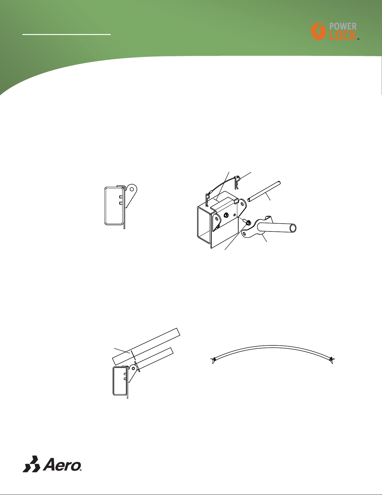
Install Latch Plate 6 18
Install PowerLock™ Pivot Box (Front and Rear) 7 19
Install PowerLock™ Spring Assembly (Front and Rear) 8 20
Install PowerLock™ Swing Arm Assembly (Front and Rear) 9 21
Install Roll Pipe 10 22
Install Cut Swing Arm 11 23
Place Labels 12 24
PowerLock™ Semi-trailer Truck Wiring 13a 25
PowerLock™ Semi-trailer Wiring 13b 26
PowerLock™ Optional Remote Wiring 13c 26
PowerLock™ Alternate Remote Wiring 13d 27
How to operate PowerLock™ 28
Safety Messages related to the Operaton of PowerLock™ 28
How to maintain PowerLock™ 29
Safety Messages related to the Maintenance of PowerLock™ 29

PowerLock™
FOR GRAIN TRAILERS
3
™
Important Safety Information
Label part# 0920-103001
6CTR/756DG
HWNN[EQXGTGFQT
WPEQXGTGFDGHQTG
FTKXKPI
&1016QRGTCVG
YJGPFCOCIGF
/#+06'0#0%'+05647%6+105
* Refer to Maintenance sheet or website.
* Repairs must ONLY be made after proper instruction.
* Spring tension must be properly released before repairs.
* Replace damaged or broken parts.
* Keep path of arms clear.
YYY RQYGTNQEMOCKPVGPCPEG EQO
12'4#6+10+05647%6+105
* Refer to Operations sheet or website.
* Only drive with tarp in fully covered or uncovered
position.
* Routinely inspect tarp and arms and replace if damaged.
YYY RQYGTNQEMQRGTCVKQP EQO
&1016UVCPFKPVJGRCVJ
QHVJGHTQPVTGCTUYKPI
CTOUQTKPLWT[EQWNFQEEWT
5RTKPIUCPFCTOUCTGWPFGTGZVTGOGVGPUKQP
&1016UVCPFKPVJGRCVJQHVJGUYKPICTOU
$TQMGPQTFCOCIGF
EQORQPGPVUEQWNFECWUG
FGCVJQTUGTKQWUKPLWT[

PowerLock™
FOR GRAIN TRAILERS
4
Marker or Felt Pen
Tape Measure
Protractor
Black Electrical Tape
Awl
Hammer
Saw
Hack Saw
1 1/8" hole saw
Drill Bits: 9/32", 11/32"
Sockets: 5/16", 7/16", 9/16", 3/4"
Open End or Box Wrenches: 5/16", 7/16", 9/16", 3/4"
Torx T40
Hex Key: 5/16"
Phillips: #3
Electric or Air Drill
Welder
Tools Required for Installation
This manual explains how to install and maintain a PowerLock™ Roll Tarp
system.

PowerLock™
FOR GRAIN TRAILERS
5
Installation Instructions
Step 1a
Fabric Front Cap: Mark Top Rail for Bow Placement
1) Figure 1 & 2. Mark the top rail where flat on side of trailer starts. Also mark 10" from there for heavy duty bows.
The dimension of the Radius, Diagonal, or Offset.
Double Bow Bracket Heavy Duty Bows
Figure 2
Figure 1
R
Radius Corner
Flat on side of trailer
Front
D.S.
D
Diagonal Corner
Flat on side of trailer
D.S.
Front
O
Offset Corner
Flat on side of trailer
D.S.
Front
R, D or O
10"
Flat on side of trailer
D.S.
Front
R, D or O10"
Flat on side of trailer
D.S.
Front

PowerLock™
FOR GRAIN TRAILERS
6
Installation Instructions
Step 1b
Fabric Front Cap: Install Double Bow Bracket or Heavy Duty Bows
1) Figure 3. Clamp first pocket of double bow bracket centered on mark on top rail.
2) Figure 4. Position bracket as shown to reduce tarp wear.
3a) Figure 3. Attach with 3/8 x 1 type F HWH bolts.
3b) Figure 5. Attach with 3/8 x 2-1/2 carriage bolts.
Index Description Qty
1 Fabric Front Cap 1
2 Double Bow or Heavy Duty Bracket 2
3 Bows 2
Index Description Qty
4 3/8 x 1 Type F HWH 8
5 5/16 x 1-1/2 Type F Torx 15
6 Aluminum Flat Bar 1/8" x 1" 12 ft
10"
R, D or O
10"
R, D or O
Figure 3
Double Bow Bracket Heavy Duty Bows
Figure 4
Hardware to Mount to Sideboards
Index Description Qty
7 5/16 X 2-1/2 CARRIAGE BOLT 8
8 5/16 FLAT WASHER 8
9 5/16 LOCK WASHER 8
10 5/16 HEX NUT 8
Install Double Bow Bracket to Sideboards
Figure 5

PowerLock™
FOR GRAIN TRAILERS
7
Installation Instructions
Figure 8
5/16 x 1-1/2 Type F Torx
Aluminum Flat Bar
4) Figure 6 & 7. Feed aluminum flat bar through bottom of fabric cap.
5) Figure 6. Feed bow through top of fabric cap.
6) Figure 7. Pull cap tight over top rail.
7) Figure 8. Drill holes evenly spaced through aluminum flat bar and attach with 5/16 x 1-1 /2 Type F Torx.
Figure 6
Bow Through
Pocket
Fabric Front Cap
Center Bolts
Figure 7
Pull cap to tighten
Gap
Roll Tarp
Fabric Cap
No Gap
Roll Tarp
Fabric Cap
Double Bow

PowerLock™
FOR GRAIN TRAILERS
8
Installation Instructions
Step 1c
Aluminum Front Cap: Install Square Nose
1) Figure 9. Measure and make any cut-outs and place
cap on trailer.
2) Attach with 3/8 x 1 Type F HWH Bolts through trough
into top rail.
Index Description Qty
1 Front Cap Square Aluminum 1
2 3/8 x 1 Type F HWH 4
Step 1d
Aluminum Front Cap: Install Shaped to Nose
1) Place cap on front of trailer, center and push lip up
against the trailer.
2) Figure 10. Trace the corner shape of nose onto front
cap and cut-out shape
Index Description Qty
1 Front Cap Aluminum 1
2 Aluminum Strip 1/8 x 3 2
3 3/8 x 1 Type F HWH 4
3) Figure 11. Attach with 3/8 x 1
Type F HWH Bolts through trough
into top rail.
4) Figure 11. Shape the aluminum
strip around the corner of the
trailer, mark and cut to length for
both sides.
5) Figure 12. Weld both pieces to
the front cap.
Radius Corner
Trace Shape
Diagonal Corner
Trace Shape
Offset Corner
Trace Shape
Weld
Weld
Shape
Strip
Shape Strip
Figure 10
Figure 11 Figure 12

PowerLock™
FOR GRAIN TRAILERS
9
Installation Instructions
Step 2a
Fabric Rear Cap: Install Double Bow Bracket or Heavy Duty Bows
30"
Double Bow Bracket
30"
Heavy Duty Bows
10"
Index Description Qty
1 Fabric Rear Cap 1
2 Double Bow or Heavy Duty Bracket 2
Index Description Qty
3 Bows 2
4 3/8 x 1 Type F HWH 8
Figure 13
Figure 14
Hardware to Mount to Sideboards
Index Description Qty
5 5/16 X 2-1/2 CARRIAGE BOLT 8
6 5/16 FLAT WASHER 8
7 5/16 LOCK WASHER 8
8 5/16 HEX NUT 8
Figure 15
Install Double Bow Bracket to Sideboards
1) Figure 13. Measure and mark 30" from the outside of the tailgate and 10" towards the rear from the previous
mark.
2) Figure 14. Clamp first pocket of double bow bracket centered on mark on top rail.
3) Figure 14. Position bracket and bow as shown to reduce tarp wear.
4a) Figure 13. Attach with 3/8 x 1 type F HWH bolts.
4b) Figure 15. Attach with 3/8 x 2-1/2 carriage bolts.

PowerLock™
FOR GRAIN TRAILERS
10
Installation Instructions
Center Bolts
Bow Through
Pocket
Tail
Fabric Rear Cap
Figure 16
5) Figure 16. Feed bow through top of fabric cap and install on trailer.
6) Figure 17. Pull cap tight when securing with Latch Plate or Roll Stop.
No Gap
Roll Tarp
Fabric Cap
Figure 17
Gap
Roll Tarp
Fabric Cap

PowerLock™
FOR GRAIN TRAILERS
11
Installation Instructions
Step 2b
Aluminum Rear Cap: Install Mounted to Tailgate
Step 2c
Aluminum Rear Cap: Install with Fabric Tail
20"
3/8 x 1 Type F HWH
Aluminum Cap
Index Description Qty
1 Rear Cap Aluminum Tailgate 1
2 3/8 x 1 Type F HWH 4
Index Description Qty
1 Rear Cap Aluminum with Tail 1
2 Fabric Rear Tail for Aluminum Cap 1
3 3/8 x 1 Type F HWH 4
1) Figure 18. Position aluminum rear cap centered on
inside of tailgate with the bottom of the trough even
with the side walls.
2) Drill pilot holes and secure with 3/8 x 1 Type F HWH
bolts.
1) Figure 1+. Position aluminum rear cap on top rail
centered on width, locate the front edge of cap 20" from
outside of tailgate.
2) Drill pilot holes and secure with 3/8 x 1 Type F HWH bolts.
3) Figure 20. Insert welt on tail into Keder on back of cap
and center on width. Use light oil to slide welt in keder.
4) Secure tail with rubber straps. See STEP 9 on installing
J-hooks for straps.
3/8 x 1 Type F HWH
Aluminum Cap
Figure 18
Figure 19
Aluminum Cap
Fabric Tail
Figure 20
Keeder
Welt

PowerLock™
FOR GRAIN TRAILERS
12
Installation Instructions
Step 3a
Marking Bow Location
1) Mark top rail according to what caps are on the trailer.
First bow
after cap
Equally spaced
not to exceed 48"
18" 18"
Front
Tailgate
Fabric Front Cap
Fabric Rear Cap
First bow
before cap
18"
Equally spaced
not to exceed 48"
18"
Front
Tailgate
Aluminum Front Cap
Aluminum Rear Cap
Mounted to Tailgate
First bow
before cap
First bow
after cap
Equally spaced
not to exceed 48"
18" 18"
20"
Front
Tailgate
Aluminum Front Cap
Aluminum Rear Cap
with Tail
First bow
before cap
First bow
after cap
Equally spaced not to exceed 48"
30"
Fabric Front Flap
Fabric Rear Tail
R, D or O
8" if square
First bow Last bow
Equally spaced
not to exceed 48"
18" 30"
Front
Tailgate
Aluminum Front Cap
Fabric Rear Tail
First bow
after cap
Last bow
18"
Front
Fabric Front Cap
Fabric Rear Tail
Equally spaced
not to exceed 48"
30"
Tailgate
First bow
after cap
Last bow

PowerLock™
FOR GRAIN TRAILERS
13
Installation Instructions
Step 3b
Installing Aluminum Bows
1) Figure 21. Align aluminum pocket with marked bow location and
flush with top of rail.
WELD
2A) Weld down each side of pocket.
BOLT
2B) Drill a pilot hole and attach with 3/8 x 1 type F HWH bolts.
3) Figure 22. Insert bow into pockets.
Step 3c
Installing Adjustable Steel Bows
1) Figures 23 & 24. Align steel pocket with marked bow location and adjust height so bend in bow is even with
the top rail.
2a) Figure 24. Drill a pilot hole and attach with 3/8 x 1 type F HWH bolts.
2b) Figure 25. Drill a pilot hole and attach with 3/8 x 1 type F HWH bolts.
3) Figure 26. Loosen set screw on bow. Insert bow into pockets into one pocket and adjust width and insert in
other pocket and tighten set screw.
Mark on
top rail
3/8 x 1 Type F HWH
Figure 21
Figure 22
Set Screw
Figure 26
Bracket can be positioned high or low
Figure 23
Mark on
top rail
3/8 x 1 Type F HWH
Figure 24
Figure 25
Hardware to Mount to Sideboards
Index Description Qty
1 5/16 X 2-1/2 CARRIAGE BOLT 8
2 5/16 FLAT WASHER 8
3 5/16 LOCK WASHER 8
4 5/16 HEX NUT 8
Install Bow Bracket to Sideboards
PowerLock™
FOR GRAIN TRAILERS
14
Installation Instructions
Step 3d
Installing Heavy Duty Bows
1) Figures 27 & 28. Align bracket with marked bow location and place on top of rail.
2) Figure 28. Drill a pilot hole and attach with 3/8 x 1 type F HWH bolts. Repeat for opposite side.
3) Figure 28. Attach swivel bracket assembly to base with headless pin and cotter pins.
4) On opposite side attach heavy duty bow assembly with headless pin and cotter pin.
Figure 27
3/8 x 1 Type F HWH
Mark on
top rail Cotter Pins
Headless Pin
Swivel Bracket
Assembly
Figure 28
Figure 30
Mark and cut bow
Figure 29
5) Figure 29. Mark heavy duty bow assembly, disassemble, and cut to length.
6) Figure 30. Reassemble with swivel bracket assembly inserted into the heavy duty bow assembly.

PowerLock™
FOR GRAIN TRAILERS
15
Installation Instructions
25°-30°
25°-30°
Inside Trailer Width
+ 2” for 10” Rise
+ 4” for 12” Rise
Figure 34
Figure 35
3) Figure 34. Cut both ends of the flex bow at 250 - 300angle and 2" longer than the inside width of the trailer.
4) Figure 35. Insert bow into pockets.
Step 3e
Installing Flex Bows
BOLT
1A) Figures 31. Align pocket with marked bow location and flush with top of rail. Drill a pilot hole and attach
with 3/8 x 1 type F HWH bolts.
WELD
1B) Figure 31 & 32. Align pocket with marked bow location and flush with top of rail. Weld all around pocket.
Mark on top rail
3/8 x 1 Type F HWH
Figure 31
Bolt
Figure 32
Weld
Mark on top rail
Figure 33. For sideboard installation weld a plate
to weld or bolt the pocket to.
Mark on top rail
Weld plate to top rail
Support plate
Figure 33

PowerLock™
FOR GRAIN TRAILERS
16
Installation Instructions
Step 4a
Assemble Anchor Pipe and Roll Pipe
1) See Figures 36 & 37. Attach lengths of anchor pipe and roll pipe and weld together.
Swaged End
Figure 36
Weld
Figure 37
Figure 38
Step 4b
Position Tarp on Trailer
1"
1"
Tarp Position Fabric Caps
1" 1"
Tarp Position Aluminum Caps
1) Figures 39 & 40. Roll the tarp onto the roll pipe and place on the trailer. Position the tarp front to back
accordingly.
Figure 39 Figure 40
2) See Figure 38. Cut the anchor pipe
flush with the ends of the pocket on the
tarp.
3) Place rubber cups on ends of anchor
pipe.
4) See Figure 38 Slide the anchor pipe
into the tarp pocket and secure with #14
x 1 PPH self drilling screw at each end.
5) See Figure 38. Slide the roll pipe
into the other pocket and leaving 1/4"
sticking out at the REAR of the tarp.
6) See Figure 38. At each strap secure
tarp to roll pipe with U-clamp and #14 x
1 PPH self drilling screw.
Anchor Pipe
U-Clamp Rear Strap
Roll Pipe
Fold Crease
Strap
1/4" x 1"
Self-drilling Screw
1/4"
at Rear

PowerLock™
FOR GRAIN TRAILERS
17
Installation Instructions
Step 5
Installing Roll Stops and Secure Anchor Pipe
1) Place tarp on trailer body and center on caps.
2) Figure 41. Locate first roll stop bracket 4"-8" from end of
anchor pipe and 1" down from top rail.
3a) Figure 42. Drill a pilot hole and attach with 3/8 x 1 type
F HWH bolts.
3b) Figures 42 & 43. Drill a pilot hole and attach with 3/8
x 2-1/2 carriage bolts.
4) Locate last roll stop bracket 4"-8" from end of anchor pipe
or as close as possible and 1" down from top rail.
5) Evenly space roll stop brackets along top rail with maximum
of 96" apart.
6) Place anchor pipe into roll stop and assemble roll stop.
Roll
Stop
Bracket
4" - 8”
as close as possible
each end
1"
Figure 41
Install Anchor Pipe & Roll
Stops to Sideboards Install Anchor Pipe to Top Rail
& Roll Stops to Sideboards
Hardware to Mount to Sideboards
Index Description
1 5/16 X 2-1/2 CARRIAGE BOLT
2 5/16 FLAT WASHER
3 5/16 LOCK WASHER
4 5/16 HEX NUT
5 1/8" x 1" x 12' FLAT ALUMINUM
6 SCREW #14 X 1 HWH AB ZINC
7 CLAMP, ANCHOR PIPE
8 3/8 X 1 TYPE F HWH BOLT
Figure 42
Figure 43

PowerLock™
FOR GRAIN TRAILERS
18
Installation Instructions
1) Figures 44 & 45. Locate the latch plate 3" forward of the front edge of the
tarp and 1"-5" below the top rail or as high as possible.
2) Figure 46. Drill a pilot hole 2"-4" in from each end and every 24" in each
section.
3a) Figure 45. Attach with 3/8 x 1 type F HWH bolts.
3b) Figure 47. Attach with 3/8 x 2-1/2 carriage bolts.
4) Cut the last section so it goes back at least 3" past the end of the tarp.
Step 6
Install Latch Plate
24"
2”- 4"
Top Rail
Latch Plate
24"
(Typical) 2”- 4"
Figure 46
Figure 44
Front Edge
of Tarp
Latch
Plate
3"
Figure 45
Top Rail
1" to 5"
Maximum
Latch Plate
3/8" x 1"
Hardware to Mount to Sideboards
Index Description Qty
1 5/16 X 2-1/2 CARRIAGE BOLT 8
2 5/16 FLAT WASHER 8
3 5/16 LOCK WASHER 8
4 5/16 HEX NUT 8
Install Latch Plate to Sideboards
Figure 47

PowerLock™
FOR GRAIN TRAILERS
19
Installation Instructions
Step 7
Install PowerLock™ Pivot Box (Front and Rear)
Index Description Qty
1 Pivot Box Grain Style 2
2 Pivot Mounting Plate 2
3 1/2-13 x 1-3/4 FHCS 4
4 1/2-13 Nylon Hex Nut 4
Index Description Qty
5 1/2 Flat Washer 4
6 3/8-16 x 1-1/2 Hex Bolt 8
7 3/8-16 Nylon Hex Nut 8
8 3/8 Flat Washer 8
1) See Figure 48. Attach the mounting plate to the pivot box with the provided fasteners.
2) See Figure 49. At the FRONT and REAR of the trailer find location for pivot box mount.
3) See Figure 50. Drill clearance holes and secure with 3/8-16 x 2-3/4 hex bolt, washers, and nylon nut.
Figure 48
Pivot Box
Mounting
Plate
1/2-13 X 1-3/4 FHCS
1/2 FLAT WASHER
1/2-13 HEX NUT
Figure 50
3/8-16 X 1-1/2 HEX BOLT
3/8 FLAT WASHER
3/8-16 HEX NUT
Figure 49
S
S
REAR
FRONT

PowerLock™
FOR GRAIN TRAILERS
20
Installation Instructions
1) See Figure 51 & 52. Mount the spring assembly onto the mounting plate and secure with collar and screw.
Step 8
Install PowerLock™ Spring Assembly (Front and Rear)
Figure 52
D.S.
Front View
Figure 51
Spring Assembly
Mounting Plate
Collar and Screw
Rear View
Washer
Washer
REAR
FRONT
D.S.
Rear View
Front View
D.S.
Rear View
D.S.
FRONT
REAR
Standard Roll Reverse Roll
Optional
ÄÄÄ
ÄÄÄ
ÄÄÄ
ÄÄÄ
Table of contents
Other Aero Utility Vehicle manuals


