Aerofit IF8110 User manual


Table Of Contents
Read all precautions and instructions in this manual before using this
equipment.
! CAUTION
Important Safety Instructions-------------------------------------------------------------- 3
Instructions------------------------------------------------------------------------------------ 4
Parts List--------------------------------------------------------------------------------------- 5
Exploded View ------------------------------------------------------------------------------- 8
Measurement Guide------------------------------------------------------------------------ 9
Assembly Instructions--------------------------------------------------------------------- 10
Assembly------------------------------------------------------------------------------------- 11
Exercise Instructions---------------------------------------------------------------------- 21
Maintenance Schedule-------------------------------------------------------------------- 22
General Maintenance Information----------------------------------------------------- 23
Weight Training Tips--------------------------------------------------------------------- 24
Specifications------------------------------------------------------------------------------- 24

─ 3─
Important Safety Instructions
Before beginning any fitness program, you should obtain a complete physi-
cal examination from your physician. When using exercise equipment, basic
precautions should always be taken, including the following:
* Read all instructions before using the equipment. These instructions are
written to ensure your safety and to protect the unit.
* Do not allow children on or near the equipment.
* Use the equipment only for its intended purpose as described in this
guide. Do not use accessory attachments that are not recommended by
the manufacturer: such attachments might cause injuries.
* Wear proper exercise clothing and shoes for your workout----no loose
clothing.
* Be careful when getting on or off the equipment.
* Do not overexert yourself or work to exhaustion.
* If you feel any pain or abnormal symptoms, stop your workout immediately
and consult your physician.
* Never operate the unit when it has been dropped or damaged.
* Never drop or insert anything into any opening in the equipment.
* Always check the unit and its cables before each use. Make sure that all
fasteners and cables are secure and in good working condition.
* Frayed or worn cables can be dangerous and may cause injury.
Periodically check these cables for any indication of wear.
* Keep hands, limbs, loose clothing and long hair well out of the way of
moving parts.
* Do not attempt to lift more weight than you can control safely.
* Do not use the equipment outdoors.
Personal Safety During Assembly
* Read each step in the assembly instructions and follow the steps in
sequence. Do not skip ahead. If you skip ahead, you may learn later that
you have to disassemble components and that you may have damaged
the equipment.
* Assemble and operate the equipment on a solid, level surface. Locate the
unit a few feet from walls or furniture to provide easy access. The equip-
ment is designed for your enjoyment. By following these precautions and
using common sense, you will have many safe and pleasurable hours of
healthful exercise with the equipment.

Instructions
Before beginning assembly please take the time to read instructions
thoroughly. Please use the various lists in this manual to make sure that all
parts have been included in your shipment. When ordering, use part number
and description from the lists. Use only our replacement part when servicing.
Failure to do so will void your warranty and could result in personal injury.
The equipment is designed to provide the smoothest, most effective
exercise motion possible. After assembly, you should check all functions to
ensure correct operation. If you experience problems, first recheck the
assembly instructions to locate any possible errors made during assembly. If
you are unable to correct the problem, call your authorized dealer. Be sure to
have your serial number and this manual when calling. When all parts have
been accounted for, continue on.
Tools Required
Ratchet Wrench and Socket
Adjustable Wrench
Rubber Mallet
Hex Key Wrench Set
─ 4─

─ 5─
Par ts List
NOTE: SOME OF THESE PARTS MAY COME PRE-INSTALLED
Item NO. Part NO. Description Qty
1 IF81100100 Weight Stack Frame 1
2 IF81100200 Main Frame 1
3 IF81100300 Stand Frame 1
4 IF81100400 Sway Frame 1
5 IF81100500 Seat Pad Frame 1
6 IF81100600 Back Pad Frame 1
7 IF81100700 Back Pad Support 1
8 IF81100800 Seat Pad Support 1
9 IF81100900 Left Handle 1
10 IF81101000 Right Handle 1
11 IF81101100 Lower Crossbeam 1
12 IF81101200 Stand Crossbeam 1
13 IF81101300 Upper Crossbeam 1
14 IT90101000 Footplate 1
15 IT90101800 Rubber Footplate Cover 1
16 IF81211900 Shaft I φ25*178 1
17 IF81101700 Adjustable Handle 1
18 IF81021800 High Rear Shroud 1493*550*3 1
19 IF81101900 High Front Shroud 1493*550*3 1
20 IF81162200 Top Shroud 1
21 SG500110400 4.5" Pulley 5
22 CWRVL0052100P166C Handball 1
23 IF81102300 Cable 1
24 IF81162700 Plastic Plate 128.5*121.9*1.5 2
25 IF81102500 Seat Pad 1
26 IF18602500 Back Pad 1
27 FS543400 Wheel 4
28 ROC-IT4014500 Grip φ30*φ22*160 2
29 M01402000 Bushing φ25*φ12.2*13 2
30 IF81162000 Foot Cover 6
31 IF81162100 Shroud Clip 6
32 IF81020800 Guide Rod φ25*2.5*1529 2
33 PL90165400 Top Plate 1
35 IF81163500 Selector Pin W/Coil 1
36 PTSHILO12800 Weight Rubber Bumperφ76.2*φ26.9*38.1 2
37 IN-D10154900 Pin φ18.2*92 1
38 KPS18002701 Nut M20*1.5*18 1
39 IN-D10152400 Spring φ2*φ13*38 1
40 GB1243.112A-1CLDG2 Connect Plate P=19.05 1
41 IF81211700 Shaft φ25.4*120 3
42 IF81165000 Nut 25*2.5*21.6 2
43 IF81162300 Plastic Knob - Cap φ25 2
44 IF81162400 Plastic Knob - Base φ25 2
45 IF81212000 End Cap φ38*φ11*6 8
46 AP55600 Adjustable End 1
47 GB2766005-2Z Bearing 6005-2Z 2
48 M02502000 Bushing φ38*φ25.4*18 6
49 BNH0738 Bushing φ12.7*φ9.5*9.5 2

─ 6─
Par ts List
NOTE: SOME OF THESE PARTS MAY COME PRE-INSTALLED
Item NO. Part NO. Description Qty
50 IF81223900 Mount Sleeve φ40*25 2
51 TLP-2002100 Damping Pad φ45*16.5 1
52 FS544600 Plastic Spacer φ20*φ10*16 4
53 IF81212600 Adjustable Spacer 1 4
54 FS547700 Adjustable Spacer 2 4
55 IF81105500 Bolt φ9.5*M8 1
56 IF81212500 Bolt φ9.4*86 4
57 IN-D10134700 Plastic Spacer φ10*φ6.5*6 4
58 KFFID2800
Plug □50.8*76.2 2
59 KF18606200 Plug □50.8 1
60 KFLPHS3000 Plug □30*60 4
61 KFCR1800 Plug □25.4*76.2 1
62 IN-S21003000 Plug RT30*70 1
63 GB9512DS2 Flat Washer φ13*φ24*2.5 16
65 DQ10DS2A Flat Washer φ11*φ23*2 50
66 DQ6DS2A Flat Washer φ6.6*φ15*2 2
67 NM12DS2 Nylon lock Nut M12 9
68 NM10DS2 Nylon lock Nut M10 22
69 NM8DS2 Nylon lock Nut M8 5
70 GB5780M12*105DS20 Hex Head Bolt M12*105 2
71 GB5780M12*80DS20 Hex Head Bolt M12*80 2
72 GB5780M12*65DS20 Hex Head Bolt M12*65 1
73 GB5781M12*30DS20NL Hex Head Bolt M12*30 2
74 GB5780M10*130DS20 Hex Head Bolt M10*130 2
75 GB5780M10*110DS20 Hex Head Bolt M10*110 4
76 GB5780M10*105DS20 Hex Head Bolt M10*105 3
77 GB5780M10*100DS20 Hex Head Bolt M10*100 2
78 GB5780M10*75DS20 Hex Head Bolt M10*75 3
79 GB5780M10*65DS20NL Hex Head Bolt M10*65 2
80 GB5780M10*60DS20 Hex Head Bolt M10*60 1
81 GB5780M10*50DS20 Hex Head Bolt M10*50 7
82 GB5781M10*30DS20 Hex Head Bolt M10*30 2
83 CNLM10*30*30DS2NL Flat Head Cap Screw M10*30 2
84 GB77M8*8DS18 Socket Set Screw M8*8 4
85 PNLM6*15DS2 Button Head Cap Screw M6*15 2
86 GB77M6*6DS18NL Socket Set Screw M6*6 4
87 GB819M5*15DS2 Flat Philips Screw M5*15 12
88 NBS6DHS Hex Key s=6 1
89 NBS5DHS Hex Key s=5 1
90 NBS4DHS Hex Key s=4 1
91 NBS3DHS Hex Key s=3 1
92 LW200BS Wrench 1
93 GB5780M10*110*30DS20NL Hex Head Bolt M10*110*30 1
94 GB5780M10*80DS20 Hex Head Bolt M10*80 2
95 CNLM10*25*25DS2NL Flat Head Cap Screw M10*25*25 8
96 GB5780M10*135DS20 Hex Head Bolt M10*135 1
97 YHY Lube 1

Item No. Part No. Description Qty
34 PLWS1000 Weight Plate 10LBS 16
Item No. Part No. Description Qty
34 PLWS1000 Weight Plate 10LBS 10
101 IF8WS1500 Weight Plate 15LBS 6
Item No. Part No. Description Qty
101 IF8WS1500 Weight Plate 15LBS 16
Weight Plate 170LBS
Weight Plate 200LBS
Weight Plate 250LBS
─ 7─
Parts List-Weight Plates
!There are three configuration of weights: 170LBS/200LBS/ ,
please see following form for details.
250LBS
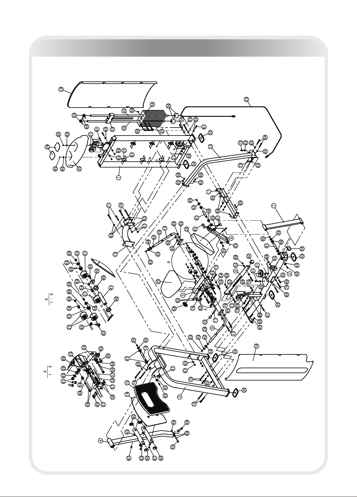
─ 8 ─
Exploded View
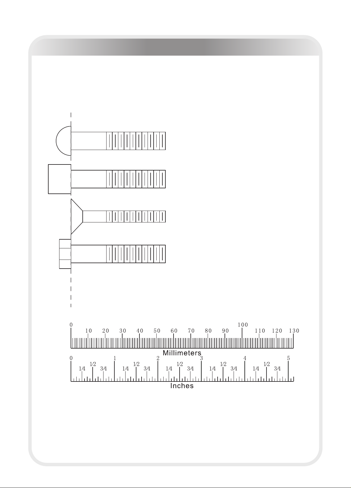
─ 9 ─
SHCS = Socket Head Cap Screw
FHCS = Flat Head Cap Screw
HHB = Hex Head Bolt
BHCS = Button Head Cap Screw
Measurement Guide

─ 10 ─
Assembly of the takes professional installers about 2 hours. If this is
the first time you have assembled this type of equipment, plan to spend more
time. It is strongly recommended to assemble the equipment by professional in-
stallers. You may find it quicker, safer, easier to assemble this equipment with
the help of a friend, as some of components may be large, heavy or awkward to
handle alone. It is important that you assemble your product in a clean, clear,
uncluttered area. This will enable you to move around the product while you are
fitting components and reduce the possibility of injury during assembly.
As with any assembled part, proper alignment and adjustment is critical. While
tightening the fasteners, be sure to leave room for adjustments. Do not fully
tighten the fasteners until instructed to do so. Be careful to assemble the com-
ponents in the sequence presented in this guide.
equipment
Assembly Instructions

─ 11 ─
Assembly
Step 1
1.Attach the Main Frame (#2) and the Lower Crossbeam (#11) to the Weight
Stack Frame(#1)using:
three M10*105 HHB (#76) one M10*110*30 HHB (#93)
seven Φ11*Φ23*2 Flat Washers (#65) three M10 Nylon Lock Nuts (#68)
2.Attach six Shroud Clips (#31) to the Weight Stack Frame (#1) using:
twelve M5*15 Flat Philips Screws (#87)
Note:Hand tighten bolts and nylon lock nuts until machine is fully assembled.

─ 12 ─
Assembly
Step 2
1.Attach the Stand Frame (#3) to the Main Frame (#2) using:
four M10*110 HHB (#75) eight Φ11*Φ23*2 Flat Washers (#65)
four M10 Nylon Lock Nuts (#68)
2.Attach the Upper Crossbeam (#13) to the Stand Frame (#3) and the Weight
Stack Frame (#1) using:
two M12*105 HHB (#70) two M12*80 HHB (#71)
eight Φ13*Φ24*2.5 Flat Washers (#63) four M12 Nylon Lock Nuts (#67)
3.Attach the Stand Crossbeam (#12) to the Stand Frame (#3) and the Lower
Crossbeam (#11) using:
two M12*30 HHB (#73) two M10*130 HHB (#74)
two M10*80 HHB (#94) two Φ13*Φ24*2.5 Flat Washers (#63)
eight Φ11*Φ23*2 Flat Washers (#65) four M10 Nylon Lock Nuts (#68)
Note: Hand tighten bolts and nylon lock nuts until machine is fully assembled.
─ 13 ─
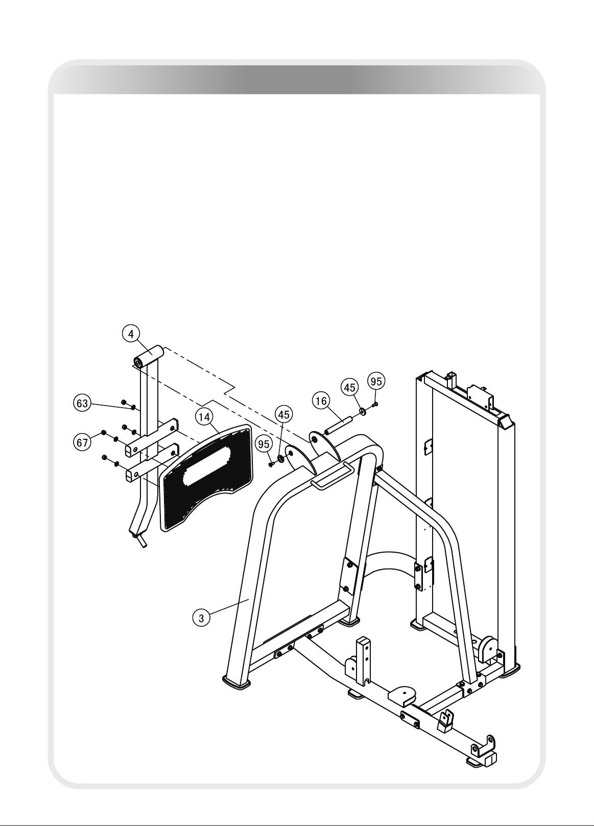
Assembly
Step 3
1.Attach the Sway Frame (#4) to the Stand Frame (#3) using:
two M10*25 Flat Head Cap Screws (#95) two Φ38*6 End Caps (#45)
one Φ25*178 Shaft I (#16)
2.Attach the Footplate (#14) to the Sway Frame (#4) using:
four Φ13*Φ4*2.5 Flat Washers (#63) four M12 Nylon lock Nuts (#67)
Note: Hand tighten bolts and nylon lock nuts until machine is fully assembled.

─ 14 ─
Assembly
Step 4
Attach five 4.5" Pulleys (#21) and the Cable (#23) to the Weight Stack Frame
(#1)、the Main Frame (#2) and the Stand Frame (#3) using:
five M10*50 HHB (#81)ten Φ11*Φ23*2 Flat Washers (#65)
five M10 Nylon Lock Nuts (#68)
The Cable (#23) and the Pulleys (#21) must be placed together, or the Cable
(#23) can not be placed correctly.
Note: Hand tighten bolts and Nylon Lock nuts until machine is fully assembled.

─ 15 ─
Assembly-170LBS
Here is the assembly instruction for 170LBS weights.
Please assemble according to the actual weights you buy.
Step 5
1.Attach:
two Φ25*2.5*1529 Guide Rods (#32) sixteen 10LBS Weight Plates (#34)
one Top Plate (#33) two Φ76.2*Φ26.9*38.1 Weight Rubber Bumpers (#36)
to the Weight Stack Frame (#1)using:
two Φ40*25 Mount Sleeves(#50) four M8*8 Socket Set Screws(#84)
2.Attach the Selector Pin W/Coil (#35) to the Top Plate (#33).
3.Attach the first 10LBS Weight Plate (#34)to the Top Plate (#33) using:
one M10*135 HHB(96) one M10 Nylon Lock Nut (#68)
4.Attach the Cable (#23) to t
Note: Hand tighten bolts and Νylon Lock nuts until machine is fully assembled.
#
he Top Plate (#33).

─ 16 ─
Assembly-200LBS
Here is the assembly instruction for 200LBS weights.
Please assemble according to the actual weights you buy.
Step 5
1.Attach :
two Φ25*2.5*1529 Guide Rods (#32) ten 10LBS Weight Plates (#34)
six 15LBS Weight Plates (#101) one Top Plate (#33)
two Φ76.2*Φ26.9*38.1 Weight Rubber Bumpers (#36)
to the Weight Stack Frame (#1)using:
two Φ40*25 Mount Sleeves(#50) four M8*8 Socket Set Screws(#84)
2.Attach the Selector Pin W/Coil (#35) to the Top Plate (#33).
3.Attach the first 10LBS Weight Plate (#34)to the Top Plate (#33) using:
one M10*135 HHB(96) one M10 Nylon Lock Nut (#68)
Note: Hand tighten bolts and Νylon Lock nuts until machine is fully assembled.
#
4.Attach the Cable (#23) to the Top Plate (#33).

─ 17 ─
Assembly-250LBS
Here is the assembly instruction for 250LBS weights.
Please assemble according to the actual weights you buy.
Step 5
1.Attach :
two Φ25*2.5*1529 Guide Rods (#32) sixteen 15LBS Weight Plates (#101)
one Top Plate (#33) two Φ76.2*Φ26.9*38.1 Weight Rubber Bumpers (#36)
to the Weight Stack Frame (#1)using:
two Φ40*25 Mount Sleeves(#50) four M8*8 Socket Set Screws(#84)
2.Attach the Selector Pin W/Coil (#35) to the Top Plate (#33).
3.Attach the first 15LBS Weight Plate (#101)to the Top Plate (#33) using:
one M10*135 HHB(96) one M10 Nylon Lock Nut (#68)
Note: Hand tighten bolts and Νylon Lock nuts until machine is fully assembled.
#
4.Attach the Cable (#23) to the Top Plate (#33).
─ 18 ─
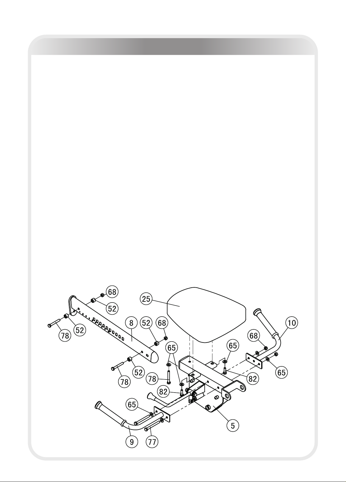
Assembly
Step 6
1.Attach the Left Handle (#9) and the Right Handle (#10) to the Seat Pad Frame
(#5) using:
two M10*100 HHB (77#) four Φ11*Φ23*2 Flat Washers (#65)
two M10 Nylon Lock Nuts (#68)
2.Attach the Seat Pad (#25) to the Seat Pad Frame(#5)using:
one M10*75 HHB (#78) two M10*30 HHB (#82)
three Φ11*Φ23*2 Flat Washers (#65)
3.Attach the Left Handle (#9) and the Right Handle (#10) to the Seat Pad Frame
(#5)using:
two M10*100 HHB (#77) four Φ11*Φ23*2 Flat Washers (#65)
two M10 Nylon Lock Nuts (#68)
4.Insert the Seat Pad Support (#8) to the Seat Pad Frame (#5) and locked with
anyone hole, attach four Φ20*Φ16 Plastic Spacer (#52) to the Seat Pad
Support(#8) ,using:
two M10*75 HHB (#78) two M10 Nylon Lock Nuts (#68)
Note: Hand tighten bolts and Nnylon lock nuts until machine is fully assembled.
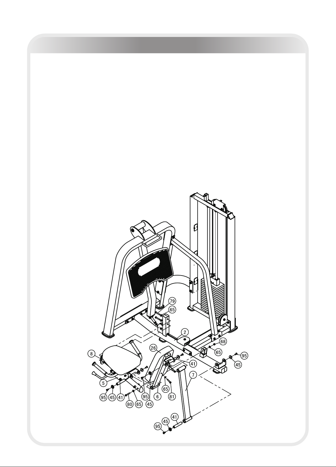
─ 19 ─
Assembly
Step 7
1.Attach the Seat Pad Support (#8) to the Main Frame (#2)using:
one M10*60 HHB (#80) two M10*65 HHB (#79)
four Φ11*Φ23*2 Flat Washers (#65) one M10 Nylon Lock Nut (#68)
2.Attach the Back Pad Frame (#6) to the Seat Pad Frame (#5) using:
two M10*25 Flat Head Cap Screws (#95) two Φ38*6 End Caps (#45)
one Φ25.4*120 Shaft (#41)
3.Attach the Back Pad (#26) to the Back Pad Frame (#6) using:
two M10*50 HHB (#81) two Φ11*Φ23*2 Flat Washers (#65)
4.Attach the Back Pad Support (#7) to the Back Pad Frame (#6) and the Seat
Pad Frame (#5) using:
four M10*25 Flat Head Cap Screws (#95) four Φ38*6 End Caps (#45)
two Φ25.4*120 Shafts (#41)
Note:Hand tighten bolts and nylon lock nuts.

Assembly
Step 8
1.Attach the High Rear Shroud (#18) and the High Front Shroud (#19) to the
Weight Stack Frame (#1).
2.Attach the Top Shroud (#20) to the Weight Stack Frame (#1)using:
two M6*15 BHCS(#85) two Φ6.6*Φ15*2 Flat Washers(#66)
Note:Wrench Tighten bolts and Nylon Lock nuts.
─ 20 ─
Table of contents


