Aerosol Magee Scientific Aethalometer AE33 User manual

Aethalometer
Model AE33
_______________________________________________________________________________________________________
Service manual –Ver. 1.0 October 2020 1/60
Aethalometer®Model AE33
Service Manual
Version 1.0
October 2020
Aerosol d.o.o., Ljubljana, Slovenia

Aethalometer
Model AE33
_______________________________________________________________________________________________________
Service manual –Ver. 1.0 October 2020 2/60
Aethalometer® Model AE33 Service Manual
Version 1.0, October 2020
Applicable for Magee Scientific Aethalometer® Model AE33
Copyright 2020 Aerosol d.o.o. Magee Scientific Aethalometer® Service Manual. All Rights
Reserved.
Aerosol d.o.o.
Kamniška 39A
SI-1000 Ljubljana
Slovenia, EU
tel: +386 1 4391 700
fax: +386 59 191 221
www.aerosol.eu
www.mageescientific.com

Aethalometer
Model AE33
_______________________________________________________________________________________________________
Service manual –Ver. 1.0 October 2020 3/60
TABLE OF CONTENTS
1GENERAL INFORMATION ...............................................................................................5
2SAFETY NOTES AND LABELS .........................................................................................6
3SERVICE PROCEDURES ON MAIN PARTS ................................................................10
3.1 ANALYTICAL CORE ASSEMBLY ................................................................................ 10
3.1.1 ANALYTICAL CORE ASSEMBLY REMOVAL PROCEDURE............................... 10
3.1.2 LED OPTICAL SOURCE REPLACEMENT ............................................................... 15
3.1.3 DETECTOR BOARD REPLACEMENT...................................................................... 18
3.1.4 CONTROLLER BOARD REPLACEMENT ................................................................ 21
3.1.5 FLOW SENSOR REPLACEMENT .............................................................................. 22
3.1.6 TAPE SENSOR REPLACEMENT ............................................................................... 25
3.1.7 SAMPLE INLET FLOW PATH CLEANING PROCEDURE...................................... 27
3.2 INTERCONNECTION BOARD ....................................................................................... 30
3.2.1 INTERCONNECTION ELECTRONIC BOARD ......................................................... 30
3.2.2 FUSES............................................................................................................................ 33
3.3 INTERNAL VACUUM PUMP ......................................................................................... 33
3.4 REAR PANEL DATA CONNECTOR PLATE ................................................................ 37
3.5 POWER SUPPLY MODULE............................................................................................ 38
3.6 COMPUTER ...................................................................................................................... 40
3.7 BALL VALVE................................................................................................................... 43
3.8 FRONT DOOR TOUCH-SCREEN MODULE................................................................. 46
4TROUBLESHOOTING.......................................................................................................49
4.1 STARTUP SCREEN CHECKS ......................................................................................... 49
4.2 INSTRUMENT STATUS .................................................................................................. 50
4.3 UNACCEPTABLE QUALITY CONTROL TEST RESULTS......................................... 51
4.4 OTHER ISSUES ................................................................................................................ 52
5SOFTWARE UPGRADE ....................................................................................................54
6DRAWINGS .........................................................................................................................55

Aethalometer
Model AE33
_______________________________________________________________________________________________________
Service manual –Ver. 1.0 October 2020 4/60
7CUSTOMER SERVICE ......................................................................................................58
8RETURNS FOR SERVICE.................................................................................................59

Aethalometer
Model AE33
_______________________________________________________________________________________________________
Service manual –Ver. 1.0 October 2020 5/60
1GENERAL INFORMATION
The Aethalometer® Model AE33.
The ‘Next Generation’ Aethalometer®, Model AE33, is a precision instrument which
incorporates scientific and technical advances to offer improved measurement performance,
user features, communications and interface: and the ability to perform routine performance
tests to verify correct operation. For optimum performance it is essential that the instrument
should be regularly maintained and correctly serviced. The Model AE33 is constructed with a
modular design, so that all sub-units or main parts may be easily serviced. This Manual presents
detailed service and maintenance procedures in a tutorial and illustrative way.
Aethalometer
Model AE33
_______________________________________________________________________________________________________
Service manual –Ver. 1.0 October 2020 6/60
2SAFETY NOTES AND LABELS
CAUTION!
READ THIS CHAPTER VERY CAREFULLY BEFORE SERVICING THE INSTRUMENT.
Instrument service procedure
Service of the instrument must be done only by trained service personnel. Regular
service trainings are offered at the Aerosol d.o.o. premises in Europe; and on-line
arrange a convenient date for training.
INCORRECT service procedures can be DANGEROUS for the service technician.
Unauthorized instrument access and operation
The instrument must not be serviced in any manner which contravenes this Manual. Unauthorized
internal access or incorrect service procedure can be dangerous. The instrument must only be serviced
by trained personnel with suitable technical skills and practical experience, who can ensure its proper
handling and service procedure.
Aethalometer
Model AE33
_______________________________________________________________________________________________________
Service manual –Ver. 1.0 October 2020 7/60
Electric shock
CHECK the A.C. main power supply cord during regular maintenance or other service procedure. If the
supply cable is DAMAGED or FRAYED, ALWAYS replace it with a new one.
Fire and explosion
NEVER install the instrument in explosion-risk areas and never operate the equipment near flammable
substances.
Instrument overheating
ALWAYS provide adequate ventilation. NEVER install the instrument in spaces with limited air
circulation.
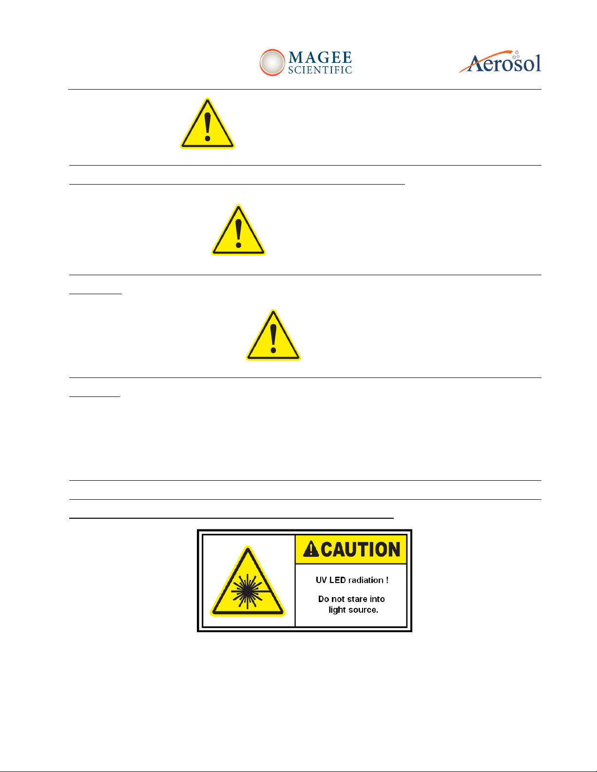
UV radiation
The AE33 light source contains ultraviolet (UV) light emitting diodes (LEDs). These LEDs radiate UV and
visible light during operation. Precautions must be taken to prevent looking directly at the UV light with
unaided eyes. NEVER touch or look directly into the AE33 light source!

Aethalometer
Model AE33
_______________________________________________________________________________________________________
Service manual –Ver. 1.0 October 2020 8/60
Instrument service and repair
UNAUTHORISED instrument service and repair procedures will VOID THE WARRANTY. The
instrument must only be serviced by authorized personnel.

Aethalometer
Model AE33
_______________________________________________________________________________________________________
Service manual –Ver. 1.0 October 2020 9/60
Moving parts
During AUTOMATIC tape advance procedure, the measurement chamber is lifted by a motorized lift
mechanism. To prevent any injuries to your fingers, NEVER place your hands or fingers into ANY
mechanical apertures during the automatic tape advance procedure.
During MANUAL chamber lift procedure ALWAYS use the chamber lift locking latch. To prevent any
injuries to your hands or fingers, NEVER place your hands or fingers into ANY mechanical apertures.
Exercise caution when lifting and releasing the chamber against its springs.
Aethalometer
Model AE33
_______________________________________________________________________________________________________
Service manual –Ver. 1.0 October 2020 10/60
3SERVICE PROCEDURES ON MAIN PARTS
3.1 ANALYTICAL CORE ASSEMBLY
3.1.1 ANALYTICAL CORE ASSEMBLY REMOVAL PROCEDURE
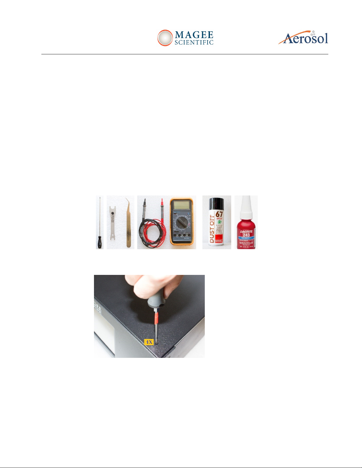
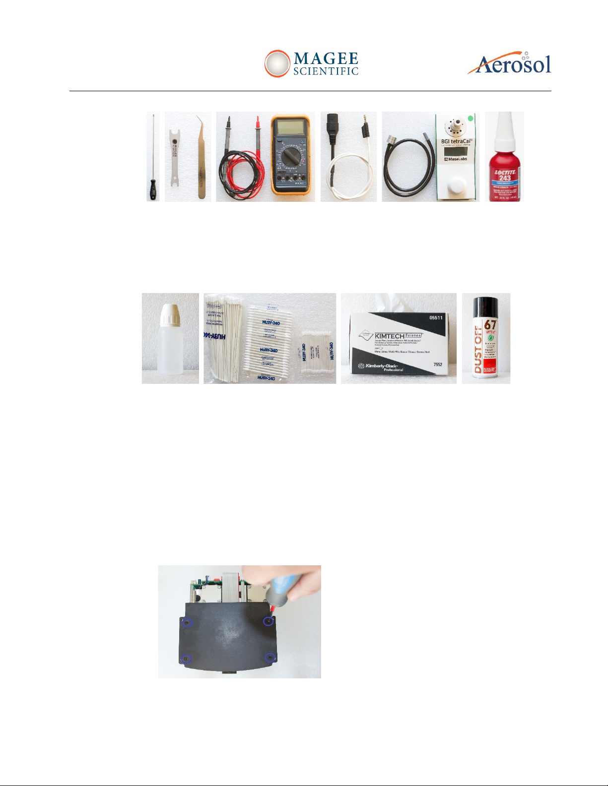
-Tools needed:
•Philips (' + ') screwdriver
•Push to connect tubing fitting tool (supplied in Aethalometer package); or flat (' –')
screwdriver
•Tweezers, long-nose pliers
•Digital voltmeter (for grounding continuity test)
•Screw thread locking adhesive (e.g., 'Loctite 243')
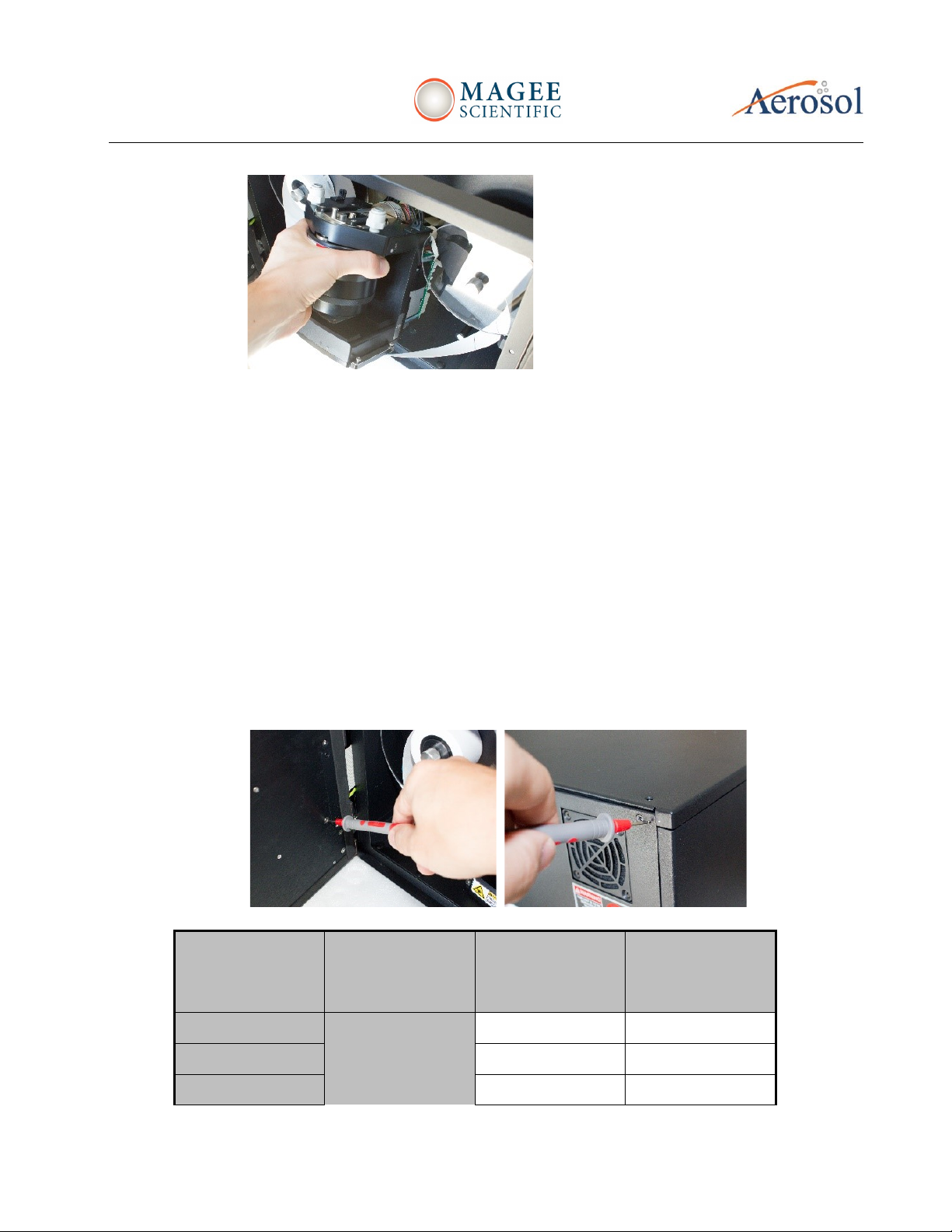
1. Turn OFF the instrument and unplug the power cord. Remove top cover (4 ‘+’ screws,
disconnect ground wire). Remove back cover (6 ‘+’ screws), disconnect ground wire.

Aethalometer
Model AE33
_______________________________________________________________________________________________________
Service manual –Ver. 1.0 October 2020 11/60
2. Please carefully follow the picture steps in the proceeding:
3. Lift the optical chamber up against its springs, lock it into place with the sliding latch
Aethalometer
Model AE33
_______________________________________________________________________________________________________
Service manual –Ver. 1.0 October 2020 12/60
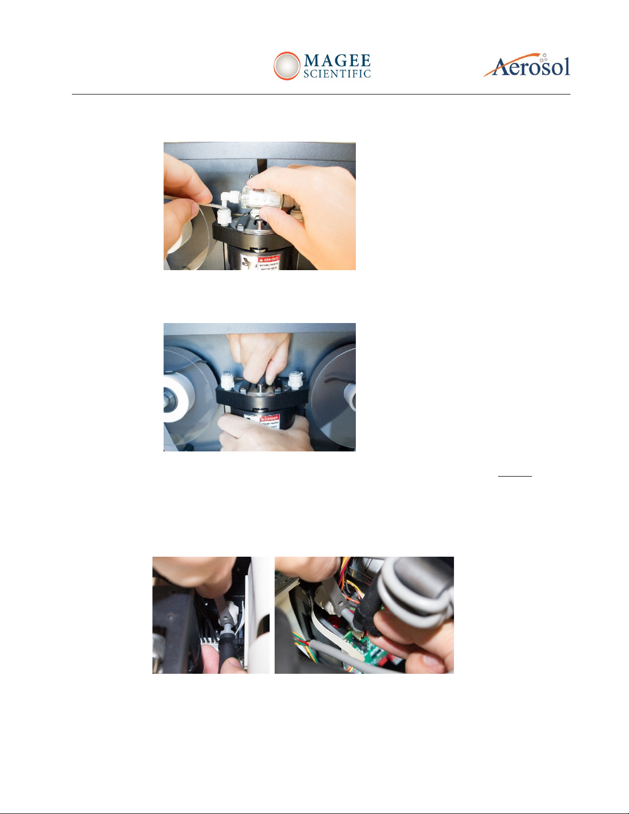
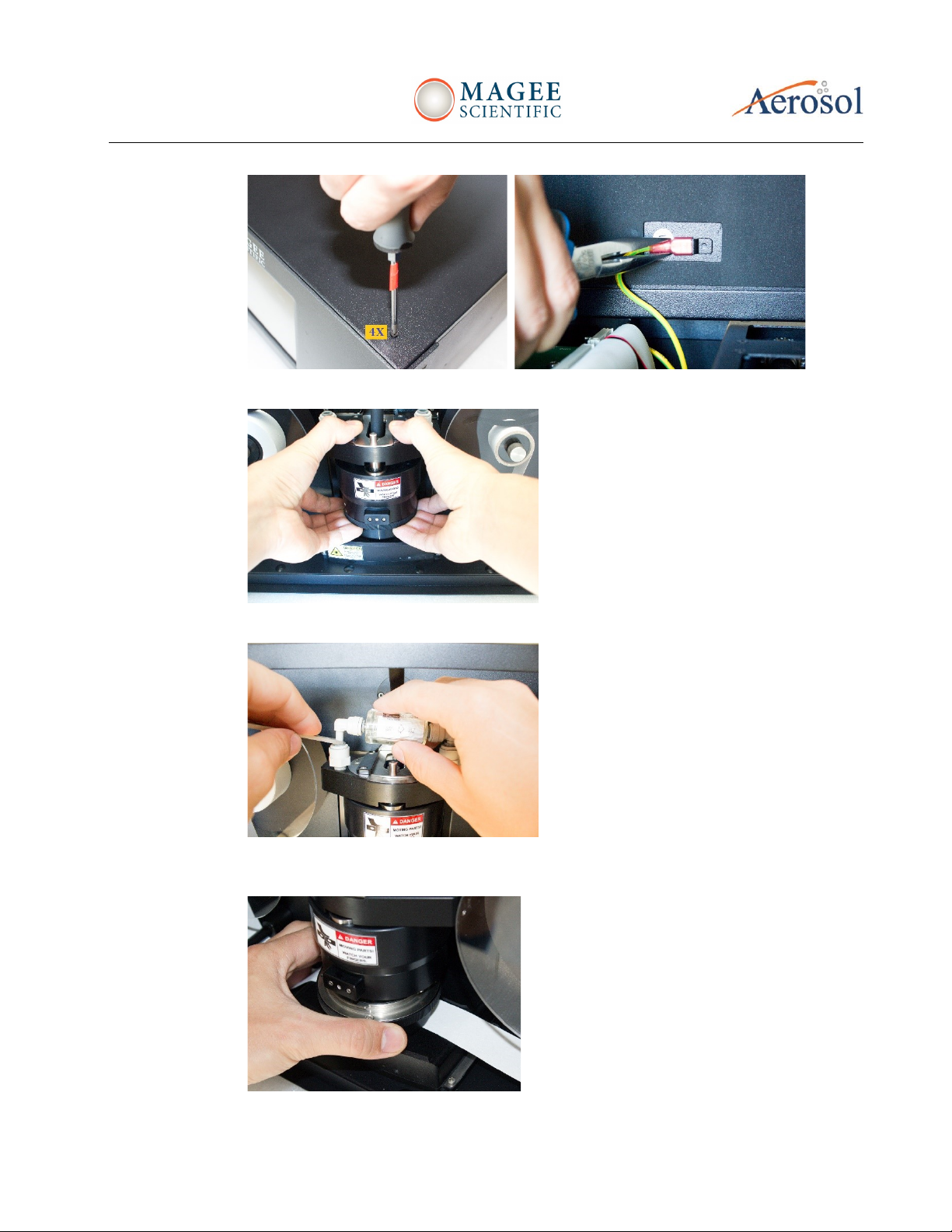
4. Remove cartridge filter (push down on gray fitting rings)
5. Disconnect the optical chamber air sample inlet tube. With one hand hold the light source
housing and with the other hand pull up slowly on the flexible inlet tube.
6. From the rear side of the analytical core unit, disconnect all the tubes and cables except: tape
sensors (4-wire ribbons), solenoid valves (plug with 6 black wires), flow sensors (2x 3-wire
plugs), and LED driver (20-wire ribbon). Do not disconnect the 20-wire ribbon which joins the
base of the controller board to the detector board underneath the base. Carefully disconnect
the tape advance motor (6-wire plug) and the pump (4-wire plug). Apply force only to the
rectangular plug body, never to the wires themselves, as this may pull them out of the contacts.

Aethalometer
Model AE33
_______________________________________________________________________________________________________
Service manual –Ver. 1.0 October 2020 13/60
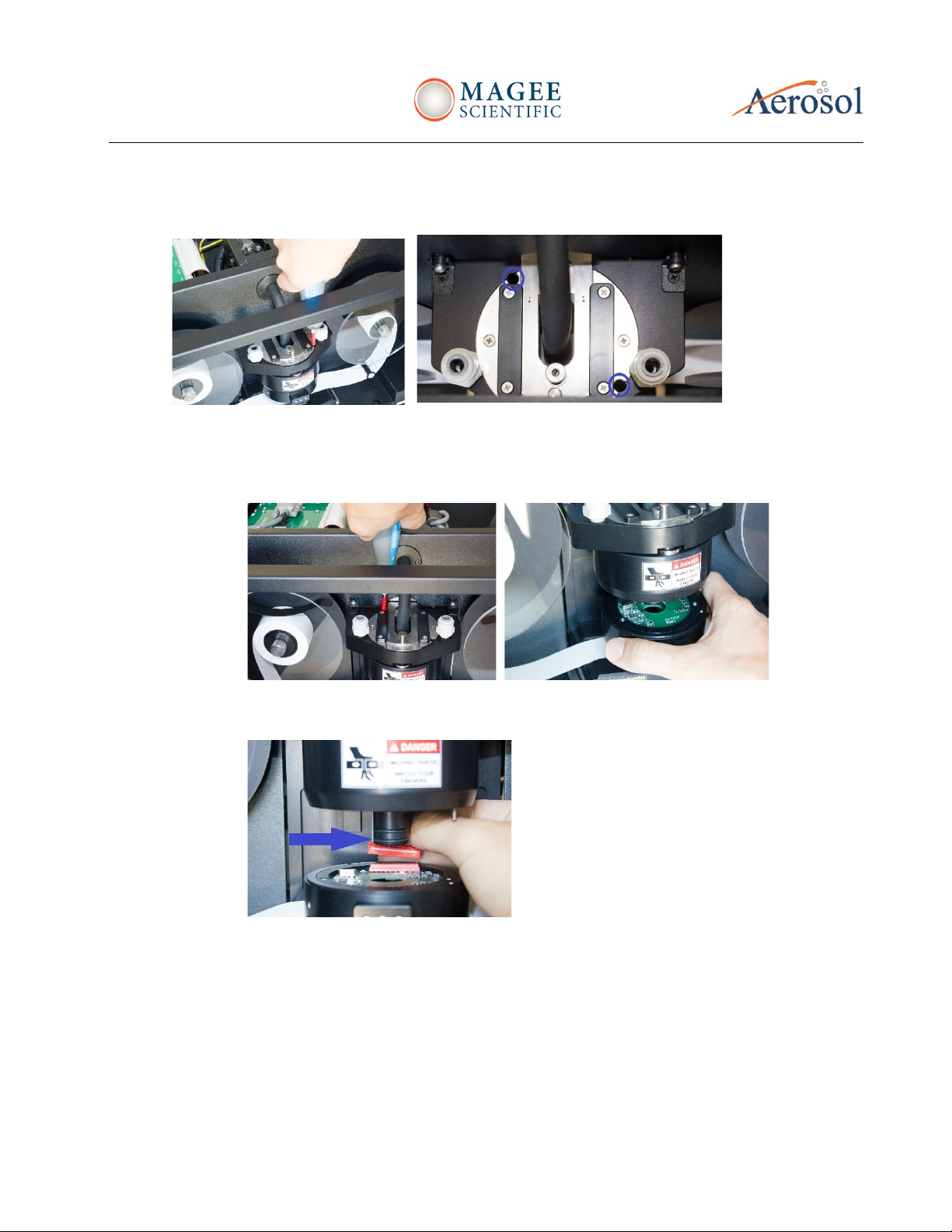
7. Remove filter tape
8. Unscrew the 6 screws which secure the assembly to the chassis: 3 on each side as shown below
(green circles)
9. Slightly tilt the assembly while removing it from the chassis.
Aethalometer
Model AE33
_______________________________________________________________________________________________________
Service manual –Ver. 1.0 October 2020 14/60
You can now proceed with further service, maintenance/cleaning or procedures
to exchange defective parts on the analytical core assembly.
Analytical core re-installation procedure
1. Clean the threads of the 6 mounting screws and apply a drop of Loctite 243 to each
one. Be sure that the long metal strips are in place between the screws and the
baseplate on either side.
2. Reconnect all cables and make sure they are firmly positioned. Note that each plug
has a different number of contacts: it is not possible to plug the »wrong plug into
the wrong socket«.
3. Make sure the air inlet and outlet tubes are firmly pressed on to the tubing barb
connectors, to avoid leaks.
System electrical grounding test
•Electrical safety is provided by connecting the chassis grounding (‘GND’) to the
3rd wire of the power cord. We recommend testing the GND wire connection for
proper grounding as shown below.
Resistance
between the inlet
grounding pin
and
VALUE
MEASURED
CONTINUITY
Top panel
Rear panel
Chassis
< 0.1 Ohm

Aethalometer
Model AE33
_______________________________________________________________________________________________________
Service manual –Ver. 1.0 October 2020 15/60
Front panel
* Older units (units from batch 00 only) have 4 screws on the lower baseplate for attaching the
analytical assembly: but do NOT have the two upper stabilizing screws. All subsequent instruments
have 2 additional screws at the top of the chamber frame.
3.1.2 LED OPTICAL SOURCE REPLACEMENT
-Tools needed
•Medium-size Phillips ('+') screwdriver with a shaft of minimum 6 cm length
•Digital voltmeter (for grounding continuity test)
•Modified power cord for GND continuity test (optional if available), otherwise use
digital multimeter probes to perform this test)
-Spare parts
•AE33 1 05 907_Led driver
•AE33 1 02 901_Led source
•AE33 1 99 022_Led driver board cable
•o-ring_15x1.5
•PH flat head machine screw DIN965A M3x8 zinc plated, quality 8.8
•PH Cross recessed pan head Screw DIN 7985 M2,5x10 A
•PH flat head machine screw DIN965A M2x6 A2
Procedure to disassemble and replace LED optical source
NOTE: it is not necessary to remove the analytical core assembly from the Aethalometer, in order to
simply service the LED source.
1. Turn OFF the instrument and unplug power cord
2. Remove top cover (unscrew 4 screws and disconnect ground wire)
Aethalometer
Model AE33
_______________________________________________________________________________________________________
Service manual –Ver. 1.0 October 2020 16/60
3. Lift the optical chamber up against its springs, lock it into place with the sliding latch
4. Remove cartridge filter (push down on gray fitting rings)
5. Remove lower light guide chamber: press UP on the locking button at the front; turn the
chamber to the left until its bayonet fitting releases.
Aethalometer
Model AE33
_______________________________________________________________________________________________________
Service manual –Ver. 1.0 October 2020 17/60
6. Insert the long '+' screwdriver into the two holes on the upper surface of the chamber top piece.
Unscrew 2 screws from the holder (top left picture). Hold the lower bayonet housing when
detaching the second screw.
7. Remove bayonet housing from the light source housing, disconnect ribbon cable plug from its
socket (it sometimes helps to use a long thin '-' screwdriver to push up on the ribbon plug body
in its socket. DO NOT pull on the ribbon cable itself!) Check the condition of the o-rings.
8. The lowest o-ring fits into the light guide and prevents air leakage. The other o-rings improve
the fitting of the bayonet housing only.
9. From the bayonet housing remove source fixing cover ring (3x '+' screws) and take out the LED
source assembly. This consists of two circular electronics boards connected together by 4x
plugs and sockets and with a thin spacer ring in between.

Aethalometer
Model AE33
_______________________________________________________________________________________________________
Service manual –Ver. 1.0 October 2020 18/60
10. Separate both PCBs (LED source and LED driver) and replace them with new electronics.
Check the orientation of the 4 plugs and sockets –there is only ONE correct way!
LED source assembling
•Put everything back in reverse order (re-attach cover ring, re-connect ribbon
cable, re-insert it into upper chamber, re-attach 2 screws with a long ´+´
screwdriver, re-insert cartridge filter, release the optical chamber and finally
replace the top cover plate). Make sure that the ribbon cable is properly
connected and not squeezed between bayonet and source housing.
System electrical grounding test
Repeat the electrical GND continuity test procedure described in Section 3.1.1.
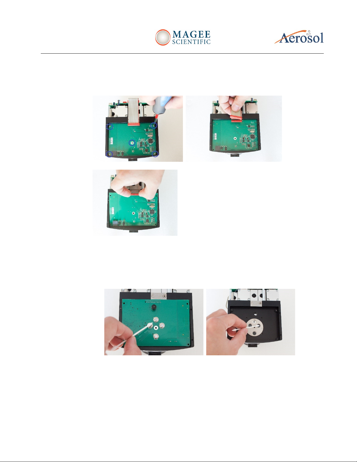
3.1.3 DETECTOR BOARD REPLACEMENT
1. Tools needed
•Philips (' + ') screwdriver
•Push to connect tubing fitting tool (supplied in Aethalometer package); or flat (' –')
screwdriver
•Tweezers, long-nose pliers
•Digital voltmeter (for grounding continuity test)
•Can of 'dust removal' pressurized spray with nozzle tube
•Screw thread locking adhesive (e.g., 'Loctite 243')
•Air flow calibrator, e.g. 'BGI TetraCal' (for leak checking)
Aethalometer
Model AE33
_______________________________________________________________________________________________________
Service manual –Ver. 1.0 October 2020 19/60
2. Cleaning equipment
•Ethanol
•Cotton-tipped swab sticks
•Cotton wipe cloths
•Can of 'dust removal' pressurized spray with nozzle tube
3. Spare parts
•AE33 1 03 903_detector board
•AE33 1 99 021_detector board cable
•PH flat head machine screw DIN965A M3x8 zinc plated, quality 8.8
•PH Cross recessed pan head Screw DIN 7985 M2,5x6 A2
•PH Cross recessed pan head Screw DIN 7985 M2,5x10 A2
4. Detector Board service procedure
1. TURN OFF the instrument and unplug the power cord
2. See Section 3.1.1 and follow the procedure to remove the analytical core
3. Turn the unit upside down and remove the detector cover baseplate
Aethalometer
Model AE33
_______________________________________________________________________________________________________
Service manual –Ver. 1.0 October 2020 20/60
4. Remove 5 screws from the detector board and pull it out holding the connector
(Note: you may need to pry it gently at each mounting hole, if it is pressed firmly
into place.)
5. Detector board replacement
•Before installing the new detector board, make sure that the front glass
lenses on all of the photodiodes are completely clean of any greasy stains,
scratches, fingerprints or dirt. Also check the cylindrical light guide tubes in
the detector housing base. Clean with swabs and alcohol if necessary.
•When re-installing the mounting screws of the detector board, do not over-
tighten the central screw: use finger-tight torque only.
6. Analytical core assembly re-installation procedure
Follow the instructions in Section 3.1.1
7. Recommended leakage test
Table of contents
Popular Measuring Instrument manuals by other brands


Keysight
Keysight M9703A Series Startup guide

Temperature Guard
Temperature Guard M309 instructions

Extech Instruments
Extech Instruments NON-DISPLAY PORTABLE user guide

NIVELCO
NIVELCO THERMOCONT TXP-1 Series user manual

Veris
Veris H681-V Series installation guide

Hanna Instruments
Hanna Instruments HI96709C instruction manual


