VTI Instruments EX1401 User manual

EX1401
16-CHANNEL ISOLATED
THERMOCOUPLE/VOLTS INSTRUMENT
USER’S MANUAL
P/N: 82-0156-000
June 20th, 2017
VTI Instruments Corp.
2031 Main Street
Irvine, CA 92614-6509
(949) 955-1894


www.vtiinstruments.com
EX1401 Preface 3
TABLE OF CONTENTS
INTRODUCTION
Certification..........................................................................................................................................................8
Warranty...............................................................................................................................................................8
Limitation of Warranty.........................................................................................................................................8
Restricted Rights Legend......................................................................................................................................8
DECLARATION OF CONFORMITY...............................................................................................................................9
GENERAL SAFETY INSTRUCTIONS...........................................................................................................................10
Terms and Symbols ............................................................................................................................................10
Warnings.............................................................................................................................................................10
SUPPORT RESOURCES .............................................................................................................................................12
SECTION 1..................................................................................................................................................................13
INTRODUCTION.......................................................................................................................................................13
Overview ............................................................................................................................................................13
Features...............................................................................................................................................................13
Combined Thermocouple and Analog Inputs................................................................................................13
Scalable for Synchronized High-Speed, High-Channel Count......................................................................14
Open Thermocouple Detection (OTD)..........................................................................................................14
Cold Junction Compensation (CJC) ..............................................................................................................14
Simplified Installation, Setup and Control ....................................................................................................14
Channel Independence ..................................................................................................................................15
Custom Thermocouple support .....................................................................................................................15
Analog Filter .................................................................................................................................................15
Digital Filter..................................................................................................................................................15
Input Connectors ...........................................................................................................................................15
Sampling Rate ...............................................................................................................................................15
Digital I/O and Limits ...................................................................................................................................15
Triggering......................................................................................................................................................16
Multi-Function Display.................................................................................................................................16
USB Data Recording.....................................................................................................................................16
End-to-End Self-test......................................................................................................................................16
EX1401 Specifications .......................................................................................................................................17
EX1401 Dimensional Diagram...........................................................................................................................21
EX1401 Rack Mount Kit Dimensional Diagram................................................................................................22
Maximizing Measurement Performance.............................................................................................................22
Utilize self-test ..............................................................................................................................................22
Allow for cold junction thermal stabilization................................................................................................22
Select the proper filter...................................................................................................................................22
Choose an appropriate sampling rate ............................................................................................................23
Select proper location for installation............................................................................................................23
Use correct wiring.........................................................................................................................................23
SECTION 2..................................................................................................................................................................25
PREPARATION FOR USE...........................................................................................................................................25
Unpacking EX1401 ............................................................................................................................................25
Installation Location...........................................................................................................................................25
Location of connectors .......................................................................................................................................26
Installation Options.............................................................................................................................................27
Rack-shelf Installation Option of EX1401....................................................................................................27
Tabletop Installation Option..........................................................................................................................28
Warm-Up Time...................................................................................................................................................28
Powering Up and Grounding..............................................................................................................................28
Software Installation...........................................................................................................................................29

VTI Instruments Corp.
4 EX1401 Preface
Driver Installation...............................................................................................................................................29
IVI Shared Components Installation (Windows Only) .................................................................................30
Instrument Driver Installation .......................................................................................................................30
Platform/LXISync Instrument Driver Installation.........................................................................................31
Network Configuration.......................................................................................................................................31
Network Configuration Reset for EX1401....................................................................................................32
Network Troubleshooting...................................................................................................................................32
Using Multiple Network Cards .....................................................................................................................33
Time Configuration ............................................................................................................................................35
Input Connections/Wiring ..................................................................................................................................35
Thermocouple Connections...........................................................................................................................35
Voltage Connections .....................................................................................................................................36
SECTION 3..................................................................................................................................................................37
BASIC OPERATION..................................................................................................................................................37
Introduction ........................................................................................................................................................37
Engineering Unit (EU) Conversion ....................................................................................................................37
Linear Correction ..........................................................................................................................................37
Voltage Measurement Ranges ............................................................................................................................38
Hardware/Analog Anti-Alias Filter ....................................................................................................................38
Digital Filter .......................................................................................................................................................38
Measurement Range/Input Protection ................................................................................................................38
Cold Junction Compensation (CJC) ...................................................................................................................39
Temperature Units..............................................................................................................................................39
Sampling Rate/Filters/Noise Floor .....................................................................................................................39
Open Transducer Detection/Overload Conditions..............................................................................................40
LED Indications..................................................................................................................................................41
Power LED (PWR)........................................................................................................................................41
LAN LED......................................................................................................................................................41
IEEE 1588 LED ............................................................................................................................................42
LEDs on Network Port..................................................................................................................................42
Channel LED Indicators................................................................................................................................42
Overload and Trigger Outputs............................................................................................................................42
Digital I/O...........................................................................................................................................................42
Triggering...........................................................................................................................................................43
Data Format........................................................................................................................................................43
Acquiring Data ...................................................................................................................................................44
Retrieving Data...................................................................................................................................................44
User-defined Conversions ..................................................................................................................................45
LCD Display.......................................................................................................................................................45
Hostname.......................................................................................................................................................45
IPv4 Address.................................................................................................................................................46
IPv6 Addresses..............................................................................................................................................46
MAC Address................................................................................................................................................46
LAN Reset.....................................................................................................................................................46
Self-Test........................................................................................................................................................47
USB...............................................................................................................................................................47
USB Memory Devices........................................................................................................................................48
Storage Devices APIs....................................................................................................................................48
Stored Configurations....................................................................................................................................48
Data Logging.................................................................................................................................................48
SECTION 4..................................................................................................................................................................49
WEB PAGE OPERATION...........................................................................................................................................49
Introduction ........................................................................................................................................................49
Common Issues...................................................................................................................................................50
Multiple Network Ports.................................................................................................................................50
Firewall .........................................................................................................................................................50

www.vtiinstruments.com
EX1401 Preface 5
General Web Page Operation .............................................................................................................................50
Login...................................................................................................................................................................52
Index...................................................................................................................................................................53
Cards...................................................................................................................................................................54
Soft Front Panel..................................................................................................................................................55
USB Storage.......................................................................................................................................................58
Network Configuration.......................................................................................................................................59
Instrument Health ...............................................................................................................................................61
Time Configuration ............................................................................................................................................62
LXI Synchronization ..........................................................................................................................................63
LXI Identification...............................................................................................................................................64
Blink LAN Indicator...........................................................................................................................................65
Change Password................................................................................................................................................66
Nonvolatile Memory...........................................................................................................................................66
Upgrade ..............................................................................................................................................................67
Reset...................................................................................................................................................................67
Reboot.................................................................................................................................................................67
SECTION 5..................................................................................................................................................................68
INSTRUMENT DRIVERS............................................................................................................................................68
Overview ............................................................................................................................................................68
IVI Drivers..........................................................................................................................................................68
Header and Library Files...............................................................................................................................68
Drivers for Linux OS..........................................................................................................................................69
Header and Library Files...............................................................................................................................69
Building and Running Example Programs .........................................................................................................69
Windows Examples.......................................................................................................................................69
Linux Examples.............................................................................................................................................70
COMPATIBILITY......................................................................................................................................................70
Driver and Firmware Revisions..........................................................................................................................70
Driver API and Instruments................................................................................................................................70
DRIVER STRUCTURE ...............................................................................................................................................72
Measurement ......................................................................................................................................................72
Channels and Channel Groups............................................................................................................................72
Start, Arm, Trigger, and Alarm...........................................................................................................................73
Sync...............................................................................................................................................................74
Start...............................................................................................................................................................74
Arm ...............................................................................................................................................................74
Trigger...........................................................................................................................................................74
Trigger Holdoff .............................................................................................................................................76
Alarms...........................................................................................................................................................78
Retrieving Data...................................................................................................................................................79
FIFO Read.....................................................................................................................................................79
Streaming ......................................................................................................................................................79
Reference Clock and Time Stamps.....................................................................................................................80
LXI and LAN Events..........................................................................................................................................80
IVI Class Compliant Interfaces...........................................................................................................................80
MULTIPLE INSTRUMENTS........................................................................................................................................81
Initializing with Multiple Instruments ................................................................................................................81
Multiple Instrument Coordination ......................................................................................................................81
DATA ACQUISITION................................................................................................................................................83
Data Flow ...........................................................................................................................................................83
FIFO ...................................................................................................................................................................83
Data Streaming ...................................................................................................................................................83
Memory Streaming........................................................................................................................................84
Disk Streaming..............................................................................................................................................84
Callback Streaming .......................................................................................................................................84
Sampling Rates...................................................................................................................................................84

VTI Instruments Corp.
6 EX1401 Preface
ClockFrequency ............................................................................................................................................85
Prescaler........................................................................................................................................................85
DownsamplingFactor ....................................................................................................................................85
FilterType......................................................................................................................................................85
SampleRate ...................................................................................................................................................85
Span...............................................................................................................................................................85
FilterCoefficients...........................................................................................................................................86
GroupDelay...................................................................................................................................................86
RecordSize ....................................................................................................................................................86
Setting The Sample Rate...............................................................................................................................86
DIO Sample Rate ..........................................................................................................................................87
Overloads and Open Transducer Detection........................................................................................................87
Time Stamps.......................................................................................................................................................88
Additional Data...................................................................................................................................................88
MEASUREMENT PROCESS .......................................................................................................................................89
Measurement Setup ............................................................................................................................................89
Sync and Coordination..................................................................................................................................89
Start, Arm, and Trigger .................................................................................................................................89
Sampling Parameters.....................................................................................................................................89
Analog Front End..........................................................................................................................................90
Measurement Initiation.......................................................................................................................................90
Measurement Loop.............................................................................................................................................90
Arming................................................................................................................................................................90
Self-arming....................................................................................................................................................90
Arming by User’s Command ........................................................................................................................90
Arming at a Certain Time Interval ................................................................................................................90
Arming by External Pulse .............................................................................................................................90
Arming from DIO Lines................................................................................................................................90
Arming from LAN Events by Other Instruments..........................................................................................91
Triggering...........................................................................................................................................................91
Self-triggering ...............................................................................................................................................91
Triggering by User’s Command....................................................................................................................91
Triggering at a Certain Time Interval............................................................................................................91
Triggering by Analog Signal.........................................................................................................................91
Triggering by External Pulse.........................................................................................................................91
Triggering from DIO Lines ...........................................................................................................................91
Triggering from LAN Events by Other Instruments .....................................................................................91
Data Retrieval.....................................................................................................................................................92
Pipeline Delay and Latency...........................................................................................................................92
Events.................................................................................................................................................................92
WHERE TO FIND MORE INFORMATION....................................................................................................................93
Driver API Reference .........................................................................................................................................93
Specification Information...................................................................................................................................93
SECTION 6..................................................................................................................................................................95
OPERATION OF DATA LOGGER ...............................................................................................................................95
Introduction ........................................................................................................................................................95
USB Disk Selection and Preparation..................................................................................................................95
USB Disk Insertion and Safe Removal...............................................................................................................95
Configuration of USB Disk ................................................................................................................................96
Saving Data to USB Disk ...................................................................................................................................96
HDF5 File Hierarchy..........................................................................................................................................96
SECTION 7..................................................................................................................................................................99
THEORY OF OPERATION..........................................................................................................................................99
Introduction ........................................................................................................................................................99
Voltage/Thermocouple Input..............................................................................................................................99
Programmable Gain Amplifier .........................................................................................................................100

www.vtiinstruments.com
EX1401 Preface 7
Analog to Digital Conversion...........................................................................................................................100
Built In Self-test and CJC measurement...........................................................................................................100
Thermocouple Calculations..............................................................................................................................101
SECTION 8................................................................................................................................................................103
CALIBRATION .......................................................................................................................................................103
Introduction ......................................................................................................................................................103
Required Resources..........................................................................................................................................103
Equipment Needed ......................................................................................................................................103
Cables Needed.............................................................................................................................................103
Software Needed .........................................................................................................................................103
Preliminary Setup .............................................................................................................................................103
Clearing user coefficients and loading defaults................................................................................................103
Obtain Offset coefficients.................................................................................................................................104
Obtain Gain coefficients...................................................................................................................................105
Save Offset and Gain Coefficients....................................................................................................................105
Obtain 2.5V reference voltages ........................................................................................................................107
Save 2.5V references ........................................................................................................................................108
Custom Calibration Cable Build Instructions...................................................................................................108
SECTION 9................................................................................................................................................................109
ONBOARD MEMORY .............................................................................................................................................109
Onboard Memory and Clearing Procedure.......................................................................................................109
APPENDIX A.............................................................................................................................................................110
MULTIPLE INSTRUMENT SYSTEM..........................................................................................................................110
Overview ..........................................................................................................................................................110
Master and Slave ..............................................................................................................................................110
Synchronization Performance...........................................................................................................................110
INDEX...................................................................................................................................................................113

VTI Instruments Corp.
8 EX1401 Preface
CERTIFICATION
VTI Instruments Corp. (VTI) certifies that this product met its published specifications at the time of shipment from
the factory. VTI further certifies that its calibration measurements are traceable to the United States National Institute
of Standards and Technology (formerly National Bureau of Standards), to the extent allowed by that organization’s
calibration facility, and to the calibration facilities of other International Standards Organization members.
WARRANTY
The product referred to herein is warranted against defects in material and workmanship for a period of one year from
the receipt date of the product at customer’s facility. The sole and exclusive remedy for breach of any warranty
concerning these goods shall be repair or replacement of defective parts, or a refund of the purchase price, to be
determined at the option of VTI.
For warranty service or repair, this product must be returned to a VTI Instruments authorized service center. The
product shall be shipped prepaid to VTI and VTI shall prepay all returns of the product to the buyer. However, the
buyer shall pay all shipping charges, duties, and taxes for products returned to VTI from another country.
VTI warrants that its software and firmware designated by VTI for use with a product will execute its programming
when properly installed on that product. VTI does not however warrant that the operation of the product, or software,
or firmware will be uninterrupted or error free.
LIMITATION OF WARRANTY
The warranty shall not apply to defects resulting from improper or inadequate maintenance by the buyer, buyer-
supplied products or interfacing, unauthorized modification or misuse, operation outside the environmental
specifications for the product, or improper site preparation or maintenance.
VTI Instruments Corp. shall not be liable for injury to property other than the goods themselves. Other than the limited
warranty stated above, VTI Instruments Corp. makes no other warranties, express or implied, with respect to the
quality of product beyond the description of the goods on the face of the contract. VTI specifically disclaims the
implied warranties of merchantability and fitness for a particular purpose.
RESTRICTED RIGHTS LEGEND
Use, duplication, or disclosure by the Government is subject to restrictions as set forth in subdivision (b)(3)(ii) of the
Rights in Technical Data and Computer Software clause in DFARS 252.227-7013.
VTI Instruments Corp.
2031 Main Street
Irvine, CA 92614-6509 U.S.A.

www.vtiinstruments.com
EX1401 Preface 9
DE C L A R A T I O N O F CO N F O R M I T Y
Declaration of Conformity According to ISO/IEC Guide 22 and EN 45014
MANUFACTURER’S NAME VTI Instruments Corp.
MANUFACTURER’S ADDRESS 2031 Main Street
Irvine, California 92614-6509
PRODUCT NAME Precision Voltage/Temperature Measurement Instrument
MODEL NUMBER(S) EX1401
PRODUCT OPTIONS All
PRODUCT CONFIGURATIONS All
VTI Instruments Corp. declares that the aforementioned product conforms to the requirements of the Low
Voltage Directive 2014/35/EU and the EMC Directive 2014/30/EU and carries the “CE” mark
accordingly. The product has been designed and manufactured according to the following specifications:
SAFETY EN 61010-1:2010 (3rd Edition)
EMC European Standards CISPR 11
EN 61000-3-2, EN 61000-3-3
EN 61326-1 (which is a product family of EMC standards which
references EN 61000-4-2, EN 61000-4-3, EN 61000-4-4, EN 61000-
4-5, EN 61000-4-6, EN 61000-4-8, and EN 61000-4-11)
SHOCK AND VIBRATION MIL-PRF-28800F, Paragraphs 4.5.5.3.1, 4.5.5.3.2, & 4.5.5.4.1
(Unit operated without error during test process)
ROHS RoHS2 Directive 2011/65/EU dated 08 June 2011
This product was tested in a typical configuration, with a shielded cable to the Digital I/O port.
I hereby declare that the aforementioned product has been designed to be in compliance with the relevant sections of the
specifications listed above as well as complying with all essential requirements of the Low Voltage Directive.
June 2017
Steve Mauga, QA Manager

VTI Instruments Corp.
10 EX1401 Preface
GENERAL SAFETY INSTRUCTIONS
Review the following safety precautions to avoid bodily injury and/or damage to the product. These
precautions must be observed during all phases of operation or service of this product. Failure to
comply with these precautions, or with specific warnings elsewhere in this manual, violates safety
standards of design, manufacture, and intended use of the product. Note that this product contains
no user serviceable parts or spare parts.
Service should only be performed by qualified personnel. Disconnect all power before servicing.
TERMS AND SYMBOLS
These terms may appear in this manual:
WARNING
Indicates that a procedure or condition may cause bodily injury or death.
CAUTION
Indicates that a procedure or condition could possibly cause damage to equipment
or loss of data.
These symbols may appear on the product:
Attention and Warning - Important safety instructions, refer to manual
Warning, possibility of electric shock, refer to manual
Frame or chassis ground
Safety ground, required to be connected to local earth ground
Indicates that the product was manufactured after August 13, 2005. This mark is
placed in accordance with EN 50419, Marking of electrical and electronic
equipment in accordance with Article 11(2) of Directive 2002/96/EC (WEEE).
End-of-life product can be returned to VTI by obtaining an RMA number. Fees
for take-back and recycling will apply if not prohibited by national law.
WARNINGS
Follow these precautions to avoid injury or damage to the product:
Apply local earth ground
The safety earth ground cable provided with this instrument meets
the required regulatory and statutory safety standards as indicated by
this product’s declaration of conformity. The green/yellow safety
cable must be applied between the safety ground on the rear of the
unit and the local safety earth ground. This is required for safe
operation of the equipment. Refer to the manual on how to apply
the safety earth ground cable.

www.vtiinstruments.com
EX1401 Preface 11
Use Proper PoE+ Source
This unit can be powered over Ethernet via PoE+ (IEEE 802.3at).
When using PoE+ to power your unit, only use VTI recommended
powered Ethernet switches, a list is available in this manual. Using
a powered switch that is not on VTI’s recommended list may not
work.
Use Proper AUX Source
This unit can be optionally powered with an external DC source.
When using the AUX DC Input to power your unit, VTI recommends
using external supply (VTI# 56-0739-000). If desired, a different DC
supply can be used if it meets the voltage, power, connector, and
safety requirements. Use a power source that meets the same safety
and CE requirements listed on the declaration of conformity for this
product. Verify that the connector pin-out is the same as required
for this product.
Avoid Electric Shock
To avoid electric shock or fire hazard, do not operate this product
with the covers removed. Do not connect or disconnect any cable,
probes, test leads, etc. while they are connected to a voltage source.
Remove all power and unplug unit before performing any service.
Service should only be performed by qualified personnel.
Operating Conditions
To avoid injury, electric shock or fire hazard:
-
Do not operate in wet or damp conditions.
-
Do not operate in an explosive atmosphere.
-
Operate or store only in specified temperature range.
-
Provide proper clearance for product ventilation to prevent
overheating.
-
DO NOT operate if any damage to this product is suspected.
Product should be inspected or serviced only by qualified
personnel
Improper Use
The operator of this instrument is advised that if the equipment is
used in a manner not specified in this manual, the protection
provided by the equipment may be impaired.
Conformity is checked by inspection.

VTI Instruments Corp.
12 EX1401 Preface
SUPPORT RESOURCES
Support resources for this product are available on the Internet and at VTI Instruments customer
support centers.
VTI Instruments Corp.
World Headquarters
VTI Instruments Corp.
2031 Main Street
Irvine, CA 92614-6509
Phone: (949) 955-1894
Fax: (949) 955-3041
VTI Instruments
Cleveland Instrument Division
5425 Warner Road
Suite 13
Valley View, OH 44125
Phone: (216) 447-8950
Fax: (216) 447-8951
AMETEK Instruments India Pvt. Ltd.
4th Floor, Block A, Divyashree NR Enclave,
Site#1, EPIP Industrial Area, Whitefield
Bangalore –560 052 India
Phone: +91 80 6782 3200
Fax: +91 80 67823232
Asia Support
Phone: +852 9177 6127
Technical Support
Phone: (949) 955-1894
Fax: (949) 955-3041
E-mail: vti.suppor[email protected]
Visit http://www.vtiinstruments.com for worldwide support sites and service plan information.

www.vtiinstruments.com
EX1401 Introduction 13
SECTION 1
INTRODUCTION
OVERVIEW
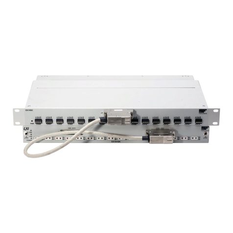
The EX1401 provides a total of 16 isolated channels for precision voltage and temperature
measurement. Its combination of measurement performance and integrity, configuration flexibility,
package density, and network connectivity make it the most powerful, yet easy-to-use, instrument
of its kind. The EX1401 is a complete, self-contained temperature measurement system that
communicates over Ethernet and can be optionally powered over the same Ethernet cable. Unlike
other data acquisition offerings in its class, the EX1401 offers a tightly integrated solution that frees
the user from the complexity of marrying terminal blocks, signal conditioning cards, digitizer, power
supply, and chassis together.
The EX1401 also provides a level of measurement integrity and channel independence that far
exceeds the typical data acquisition system. Absent are caveats about scanning speed, channel order,
and overload effects. In the EX1401, channels have no influence on each other, regardless of
scanning speed or channel state. Excellent common mode rejection performance provides immunity
from not only power line interference, but also high frequency noise. Moreover, it aids in
maintaining overall system integrity by offering a high-performance open transducer detection
system. The EX1401 provides isolation from earth and channel to channel. This provides worry free
measurements in high voltage environments like automotive and battery test.
The EX1401 provides a high level of configuration flexibility as well. Each channel can be
configured independently with regards to measurement function, filter setting, and limit values. In
addition to measuring all standard thermocouples, the EX1401 can be programmed with user-
defined thermocouple polynomial equations or be used as a low-noise voltmeter. Scanning speed is
programmable up to a maximum of 20 kSa/s (kilosamples per second), independent of the number
of channels being scanned. This combination of filtering and scanning speed provides the EX1401
with the low noise performance required for sensitive applications as well as the speed necessary to
measure fast, fine-gauge thermocouples.
For highest accuracy and stability, the EX1401 provides a precision analog temperature sensor, per
channel, to measure the cold-junction of the mini TC connector. The accuracy of this reference
junction temperature sensor is typically within +/- 0.05°C (20°C to 30°C operating temp.)
Thermocouple accuracy is detailed in the specifications.
The EX1401 is as easy-to-use as it is powerful. An integrated web page provides a convenient way
to instantly verify communications and instrument functionality, while industry standard IVI drivers
provide a familiar application programming interface to reduce integration and program
development time.
FEATURES
Combined Thermocouple and Analog Inputs
Easily combine thermocouple and analog signals on these versatile instruments with sampling rates
up to 20 kSa/s per channel. Each input incorporates an independent signal conditioning path with

VTI Instruments Corp.
14 EX1401 Introduction
software selectable filters for maximum flexibility. Complete channel independence ensures data
integrity regardless of sample speed or input overload conditions.
Scalable for Synchronized High-Speed, High-Channel Count
In addition to base class LXI compliance, this instrument also provides extended capabilities like
LXI Clock Synchronization, LXI Event Messaging, and LXI Time Stamped Data, to support easy
integration and synchronization of multiple devices, including existing VXI/PXI/PXIe bus
instrumentation.
Open Thermocouple Detection (OTD)
While the integration of the EX1401 removes many of the reliability and connectivity problems
typically faced by system designers, they still must contend with the reliability of the sensor
connections. Fortunately, the EX1401 aids a great deal in that regard as well. Each thermocouple
input channel generates a very small current (< 10 nA/channel) which drives the input to an open-
circuit state if the transducer is disconnected. Implemented in this way, open transducer detection is
continuous and requires no discrete function call on the part of the user to be activated, offering
more protection than systems that only check on command, as a broken sensor can occur at any time
during testing, not just at installation. In a typical application, the OTD has no effect on the
measurement.
NOTE Many thermocouple simulators have a much higher impedance than a thermocouple so an offset
may be introduced into the reading when using a simulator. In general, the OTD should only be
active on channels that are being used with actual thermocouples.
The EX1401 additionally offers a front panel OTD LED for each channel that illuminates upon the
recognition of a fault condition. This provides for quick and easy problem channel identification.
Moreover, to ensure that even intermittent problems are identified, the fault recognition is a latching
mechanism, retaining the information of the current acquisition sequence until a new acquisition is
initiated.
Cold Junction Compensation (CJC)
For highest accuracy and stability, the EX1401 provides a precision, analog temperature sensor, per
channel, to measure the reference/cold-junction of the mini TC connector. CJC channels are
measured with a separate, dedicated ADC, per channel and are time correlated to the thermocouple
channel. For those users that prefer to employ an external cold junction, the EX1401 also allows
for the programming input of up to sixteen unique external cold junction temperatures, one for every
input channel. Moreover, the use of internal and external CJC inputs can be mixed throughout the
unit on a per channel basis. As the CJC sensors are placed in an isothermal environment, they are
not disturbed by instrument air cooling fan, as well as thermal disturbances from adjacent channels.
Triggering
The EX1401 supports a full function trigger model with a separate arm source and trigger source
event structure. Trigger and arm source events can be independently programmed from a variety of
sources including Immediate, Software, External TTL, Digital I/O, LAN events, and LXI alarms.
Simplified Installation, Setup and Control
In addition to compliance to LXI base specifications, the EX1401 also implemented the LXI Clock
Synchronization, and LXI Event Messaging, Time Stamps and Event Logs. These features make the
EX1401 instruments ideal for distributed measurements throughout a facility –reducing cabling and
installation expense. The ability to connect directly to an Ethernet network using industry standard
Ethernet cable and connections makes it easy for network administrators to oversee the installation.
Using a PoE+ enabled Ethernet switch allows both power and measurement data on a single wire.
Experience how IVI Digitizer class driver compliance simplifies installation and setup.

www.vtiinstruments.com
EX1401 Introduction 15
An onboard, web-accessible user interface allows you to instantly verify communications and
instrument functionality, while IVI drivers provide a familiar application programming interface to
further reduce integration and program development time. For comprehensive, programming-free
data recording setup, management and viewing, use EX1401 instruments with one of VTI’s full-
featured, turnkey software solutions, such as EXLab.
Channel Independence
Each of the EX1401’s 16 differential input channels is an independent signal conditioning path,
complete with amplification and continuous open transducer detection. This independence frees the
user from the problem of channel-to-channel crosstalk that is pervasive in most multi-channel data
acquisition systems. In the EX1401, channels have no influence on each other, regardless of
scanning speed or channel state. Specifically, open or significantly overloaded channels do not affect
the measurement results of any other channels.
Custom Thermocouple support
When configured in thermocouple mode, each input can be individually configured to support
specific type of thermocouple. In addition to supporting standard thermocouple types (J, K, T, E, S,
R, B and N), the EX1401 can also support custom thermocouple types (e.g., C-Type) through the
input of user-defined thermocouple polynomial coefficients. Each of the EX1401’s channels can be
configured with a unique custom 12th order polynomial for both voltage-to-temperature and
temperature-to-voltage conversions.
Analog Filter
Each EX1401 input channel has a fixed, 2-pole, 30kHz low pass filter with an RC response
providing anti-alias filtering. The analog signals after the anti-alias filter are over sampled at 320kHz
to 640kHz by the ADCs. This combination of anti-alias filter with ADC oversampling provides
60dB of rejection at the aliasing band.
Digital Filter
The EX1401 allows the user to configure different types of digital filters per channel. These digital
filters are implemented inside the FPGA of the device, such that they perform consistently and
without loading the host computer resources. Users can optimize the filter settings for aggressive
filter performance or lower data latency time. In addition, users can customize the FIR filter
performance by editing the coefficients of the filter. This provides ultimate flexibility in designing
a filter to suit the application needs.
Input Connectors
The EX1401 employs uncompensated (Cu-Cu) mini-thermocouple female jacks as an input
connector. This connector provides a solid, reliable connection that is also easily changeable. Since
it is not thermocouple-type specific, different thermocouple types can be mixed throughout the unit
without hardware modification.
Sampling Rate
The EX1401 is designed for sampling speeds up to a 20 kSa/s per channel, regardless of the number
of enabled channels. The lowest sampling speed is 0.000002328 Hz (approximately one sample
every 5 days.)
Digital I/O and Limits
The EX1401 allows the users to define a unique set of programmable limits that are used for open
transducer detection as well as general purpose input channel monitoring. These limits are
programmable on a per channel basis and are evaluated, within the instrument with each completed

VTI Instruments Corp.
16 EX1401 Introduction
scan. The output of limit evaluations is presented via front panel LEDs, digital I/O port, LAN events,
and through the instrument driver.
The EX1401 features an 8-channel digital I/O port on the rear panel of the instrument. This port
can be used as an arm/trigger source, for presentation of limit evaluation information, and as a
general purpose output device. As a general purpose output device, each DIO channel can be
independently programmed with regards to its output functionality and its static level to assume
when enabled as an output. For expanded and more automated operation, each DIO channel can be
independently linked to one or multiple limit conditions on one or more input channels. The digital
I/O port is bank isolated to reduce ground loop noise issues with external equipment.
Triggering
The EX1401 supports a full function trigger model with a separate arm source and trigger source
event structure. Trigger and arm source events can be independently programmed from a variety of
sources including Immediate, Software, External TTL, Digital I/O, LAN events, and LXI alarms.
Multi-Function Display
The menu driven LCD display available on the rear side of the instrument provides instrument
status, diagnostic reports, network details, and can also start, stop, and monitor measurement
sequences that log data to an external USB disk without PC control.
USB Data Recording
The EX1401 can export acquisition data at full speed to an external USB memory device, so that it
can be used as a standalone data logger. This will also be useful to keep a redundant back up of data
for high reliability applications, while streaming data over the Ethernet interface. It supports
standard maximum partition size of all of EXT2, EXT3, EXT4, VFAT/FAT32, and MSDOSFS
filesystems. The data will be stored in Hierarchical Data Format, HDF5 file format. HDF5 being an
open standard data file format, users can choose from a wide variety of tools to decompress, view
and export the time stamped measurement data. For more information on HDF5 file formats and
tools, visit the HDF Group’s website: https://www.hdfgroup.org. The external USB memory device
can also be used to store the user’s desired instrument configuration.
End-to-End Self-test
The EX1401 can perform internal diagnostics through self-test mechanism. This Built-In-Self-Test
(BIST) checks for internal board voltage levels, system temperature, various status indicators,
LEDs, cooling fan, LCD display and +2.5V reference voltage on every input channel, and health of
internal CJC sensors. This self-test will be performed automatically upon power-up, and can be
initiated though software or the rear panel LCD interface, any time after the instrument is booted.
This Built-In-Self-Test provides test system confidence and peace of mind by ensuring that the
complete instrumentation measurement path is functional and delivers the most accurate result
possible.

www.vtiinstruments.com
EX1401 Introduction 17
EX1401 SPECIFICATIONS
GENERAL SPECIFICATIONS
NUMBER OF CHANNELS
EX1401
16 electrically isolated and fully differential inputs
INPUT POWER
Input voltage
Power (AUX)
10V to 50V DC, must be isolated to 1500Vrms
12 W typical, 15 W max
PoE+ Power
12 W typical, 15 W max
CHANNEL TYPES
Input channel type
Thermocouple or Voltage (software selectable, per channel)
VOLTAGE INPUT RANGE
Voltage Input Mode
Thermocouple Input Mode
±0.01 V, ±0.10 V, ±1.0 V, ±10.0 V; 10% Over-Range
±0.10 V for temperature measurement
INPUT OVERVOLTAGE PROTECTION
Up to ±100V peak between the two terminals of any mini TC connector
INPUT IMPEDANCE
20 MΩ differential (DC input)
1.7 MΩ differential (60 Hz input)
180 kΩ differential (1000 Hz input)
INPUT COUPLING
DC only
RESOLUTION
±10.0 V
±1.0 V
±0.1 V
±0.01 V
Thermocouple
1.7 uV
150 nV
13.5 nV
1.7 nV
< 0.001 °C
ACCURACY (10SPS)
± (% of reading + offset), see Conditions for Accuracy
Voltage Mode
±10.0 V
±1.0 V
±0.1 V
±0.01 V
Thermocouple Mode
Type J, K, T, E, N
Type S, R
Type B
Typical: ± (0.020% + 400uV); Max: ± (0.030% + 500uV)
Typical: ± (0.020% + 40uV); Max: ± (0.030% + 50uV)
Typical: ± (0.020% + 7uV); Max: ± (0.035% + 15uV)
Typical: ± (0.050% + 5uV); Max: ± (0.045% + 9uV)
Typical: ± (0.020% + 0.2°C); Max: ± (0.040% + 0.4°C)
Typical: ± (0.020% + 0.6°C); Max: ± (0.040% + 1.3°C)
Typical: ± (0.020% + 0.9°C); Max: ± (0.040% + 1.8°C)
STABILITY
Voltage Mode
±10.0 V
±1.0 V
±0.1 V
±0.01 V
Thermocouple
Type J, K, T, E, N
Type S, R
Type B
Typical: ± (5PPM/°C + 1.20uV/°C); Max: ± (9PPM/°C + 2.7uV/°C)
Typical: ± (5PPM/°C + 0.12uV/°C); Max: ± (9PPM/°C + 0.27uV/°C)
Typical: ± (5PPM/°C + 0.08uV/°C); Max: ± (9PPM/°C + 0.16uV/°C)
Typical: ± (9PPM/°C + 0.08uV/°C); Max: ± (14PPM/°C + 0.16uV/°C)
Typical: ± (8PPM/°C + 0.006°C/°C); Max: ± (14PPM/°C + 0.012°C/°C)
Typical: ± (8PPM/°C + 0.020°C/°C); Max: ± (14PPM/°C + 0.040°C/°C)
Typical: ± (8PPM/°C + 0.030°C/°C); Max: ± (14PPM/°C + 0.060°C/°C)
INPUT NOISE,TYPICAL
Sample Rate (SPS)
10V
1V
100mV
10mV
Temp (Type T)
10,000
900 uVpp
60 uVpp
14.0 uVpp
13.0 uVpp
0.34 °C pp
1,000
200 uVpp
13 uVpp
3.0 uVpp
2.5 uVpp
0.08 °C pp
100
60 uVpp
4 uVpp
1.0 uVpp
0.8 uVpp
0.04 °C pp
10
20 uVpp
1.5 uVpp
0.5 uVpp
0.33 uVpp
0.03 °C pp

VTI Instruments Corp.
18 EX1401 Introduction
Type
Min
Max
-100°C
0°C
100°C
300°C
500°C
700°C
900°C
1100°C
1400°C
J
-200°C
1200°C
±0.30°C
±0.20°C
±0.20°C
±0.30°C
±0.30°C
±0.30°C
±0.40°C
±0.40°C
K*
-200°C
1372°C
±0.30°C
±0.30°C
±0.30°C
±0.30°C
±0.40°C
±0.40°C
±0.50°C
±0.50°C
±0.60°C
T**
-200°C
400°C
±0.40°C
±0.30°C
±0.20°C
±0.30°C
±0.30°C
E
-200°C
900°C
±0.30°C
±0.20°C
±0.20°C
±0.20°C
±0.30°C
±0.30°C
±0.30°C
S
-50°C
1768°C
±1.40°C
±1.00°C
±0.90°C
±0.90°C
±0.90°C
±0.90°C
±0.90°C
±0.90°C
R
-50°C
1768°C
±1.40°C
±1.00°C
±0.80°C
±0.80°C
±0.80°C
±0.80°C
±0.80°C
±0.80°C
B
250°C
1820°C
±2.40°C
±1.60°C
±1.20°C
±1.10°C
±1.00°C
±1.00°C
N
-200°C
1300°C
±0.40°C
±0.30°C
±0.30°C
±0.30°C
±0.40°C
±0.40°C
±0.40°C
±0.50°C
TABLE 1-1: THERMOCOUPLE TYPICAL ACCURACY (°C)
Type
Min
Max
-100°C
0°C
100°C
300°C
500°C
700°C
900°C
1100°C
1400°C
J
-200°C
1200°C
±0.50°C
±0.40°C
±0.40°C
±0.50°C
±0.50°C
±0.60°C
±0.60°C
±0.70°C
K*
-200°C
1372°C
±0.60°C
±0.50°C
±0.50°C
±0.60°C
±0.60°C
±0.70°C
±0.80°C
±0.90°C
±1.00°C
T**
-200°C
400°C
±0.70°C
±0.50°C
±0.40°C
±0.40°C
±0.50°C
E
-200°C
900°C
±0.40°C
±0.30°C
±0.30°C
±0.40°C
±0.40°C
±0.50°C
±0.60°C
S
-50°C
1768°C
±2.90°C
±2.20°C
±1.80°C
±1.80°C
±1.70°C
±1.70°C
±1.70°C
±1.80°C
R
-50°C
1768°C
±2.90°C
±2.10°C
±1.70°C
±1.60°C
±1.60°C
±1.50°C
±1.50°C
±1.60°C
B
250°C
1820°C
±5.10°C
±3.20°C
±2.50°C
±2.20°C
±2.00°C
±1.90°C
N
-200°C
1300°C
±0.80°C
±0.70°C
±0.60°C
±0.60°C
±0.60°C
±0.70°C
±0.80°C
±0.90°C
TABLE 1-2: THERMOCOUPLE MAXIMUM ACCURACY (°C)
Conditions for Temperature Accuracy and Voltage Accuracy
•30-minute warm-up after turn ON and TC plug connected. 10 SPS acquisition rate, Low Latency CIC filter
•20 °C to 30 °C, 1 year from full calibration. Typical is defined as ± 2*Sigma (95% confidence)
•Fan must be ON. Add ±0.22°C to Typical, or ±0.34°C to Maximum if FAN is OFF
•Exclusive of externally induced noise, Common Mode Voltages (CMV), thermocouple and cable length errors
* 1400 accuracy is for 1372 °C
** 500 accuracy is for 400 °C
TABLE 1-3: CONDITIONS FOR ACCURACY

www.vtiinstruments.com
EX1401 Introduction 19
GENERAL SPECIFICATIONS
ISOLATION –ANALOG INPUTS
Basic insulation, IEC 61010-1 (3rd): Pollution degree II, Material IIIa, Altitude < 5000m, Overvoltage Category II, applicable
for secondary circuits derived from the Mains
Input channel to Ground
±500 V Peak continuous working voltage
Input channel to channel
±1000 V Peak continuous working voltage between channels
Impedance across barrier
100pF || Gas Discharge Tube rated for 600V
COMMON MODE REJECTION RATIO (CMRR), TYPICAL
DC
50/60 Hz
400 Hz
1000 Hz
10mV range
-140 dB
-140 dB
-130 dB
-110 dB
100mV range
-140 dB
-140 dB
-130 dB
-90 dB
1V range
-140 dB
-140 dB
-130 dB
-80 dB
10V range
-140 dB
-140 dB
-130 dB
-80 dB
The 10V input range is reduced by increasing common mode AC voltage above
100Vpk/60Hz.
CHANNEL TO CHANNEL CROSSTALK,TYPICAL
-145 dB < 1kHz
TOTAL HARMONIC DISTORTION (THD), 100 HZ
Voltage Mode
±10.0 V
±1.0 V
±0.1 V
Typical: -90dB
Typical: -87dB
Typical: -85dB
MEASUREMENT SAMPLING RATE
Minimum: 0.000002328 Samples per Second, per channel
Maximum: 20,000 Samples per Second, per channel
PROGRAMMABLE DIGITAL FILTERS
None (No Filter)
High Performance (FIR)
Low Latency (CIC)
Medium Latency (CIC+CFIR)
Post Filter Blind Divider
Raw data
1 to 16 number of /2 stages (Selectable & Customizable)
/4 to /8192 (Selectable)
Low latency CIC filter, followed by /4 FIR Filter (Customizable)
1 - 65536 (selectable)
CHANNEL TO CHANNEL PHASE MATCHING
<±1.5 μS
PASSBAND RIPPLE
<±0.005 dB over the passband of 0.45 * Sample Rate
CLOCKAND TRIGGER SPECIFICATIONS
ELECTRICAL SPECIFICATIONS
Maximum Input Voltage
Input Impedance
Minimum Input Pulse Width
Maximum Output Frequency (CLK)
VIL
VIH
VOL
VOH
IMAX
-0.5V to 5.5V, ESD protected
50 Ohm series terminated with a 10k Ohm pulldown resistor
1 μs
10 MHz
< 0.8V
> 3.5V
< 0.65V @ 32 mA
> 3.0 V @ 32 mA
50mA max

VTI Instruments Corp.
20 EX1401 Introduction
DIO SPECIFICATIONS
NUMBER OF DIO CHANNELS
8
ELECTRICAL SPECIFICATIONS
Maximum Input Voltage
Input Impedance
Minimum Input Pulse Width
Minimum Output Pulse Width
VIL
VIH
VOL
VOH
IMAX
-0.5V to 5.5V, ESD protected
Signal is pulled low by a 10k Ohm resistor
100 μs
100 μs, updated synchronously with the ADC sampling, prior to decimation
< 0.8V
> 2.0V
< 0.55V @ 10 mA
> 2.0 V @ 10 mA
10mA max per channel, 20mA max per bank
ISOLATION -DIGITAL
Basic insulation, IEC 61010-1 (3rd): Pollution degree II, Material IIIa, Altitude < 5000m, Overvoltage Category II, applicable
for secondary circuits derived from the Mains
Input channel to Ground
±250 V Peak continuous working voltage
Input channel to channel
None, all channels share one ground pin
Impedance across barrier
1000pF || 10MΩ || Gas Discharge Tube rated for 600V
CONNECTOR
9 pin standard D-Sub Female socket
LXI SPECIFICATIONS
NETWORK CONNECTION
10/100 Base-T (auto MDI-X)
LXI CLASS COMPLIANCE (V1.4)
LXI Core + Clock Synchronization + Event Messaging + Event Logs + Time Stamped
Data + IPv6 Support
CLOCK SPECIFICATIONS
Clock oscillator accuracy
Synchronization accuracy
Default 1588 Sync threshold
Timestamp
Accuracy
Resolution
±20 ppm (when free running as Master, with no other clocks)
±20 ns typical (with high-quality IEEE 1588 grandmaster and transparent clocks).
Reports “synchronized” when < ±300 ns of the 1588 master clock
Configurable (default is 300 ns)
As good as time synchronization down to 40 ns
40 ns
IEEE 1588-BASED TRIGGER TIMING
Alarm
Trigger time accuracy
Time to trigger delay
Receive LAN[0-7] Event
Trigger time accuracy
Time to trigger delay
Future timestamp
Past/zero timestamp
As good as time synchronization down to 40 ns
40 ns
As good as time synchronization down to 40 ns
40 ns typical
Unspecified (Based on processor workload)
HARDWARE TRIGGER TIMING
DIO IN time to trigger delay
Min: 50 ns, Max: 100 ns
EXT TRIG in to timestamp delay
Min: 46 ns, Max: 86 ns
Internal event/state to EXT TRIG
OUT time delay
Min: 40ns, Max: 80ns
Internal event/state to DIO OUT
time delay
Min: 50 ns, Max: 100 ns
LAN event in with event time !=0
0 to 40ns (because of clock granularity)
LAN event in with event time == 0
(unspecified)
LAN event out timestamp
granularity
40ns
INTERNAL DATA STORAGE
64 MSamples, shared among all enabled channels
(~6.6 minutes when sampling all 16 inputs at 10kSPS)
Other manuals for EX1401
1
Table of contents
Other VTI Instruments Measuring Instrument manuals

VTI Instruments
VTI Instruments 2008SDH-2AP User manual

VTI Instruments
VTI Instruments EX1000A User manual

VTI Instruments
VTI Instruments AMETEK EX1044A User manual

VTI Instruments
VTI Instruments Ametek EX1200A Series User manual

VTI Instruments
VTI Instruments EX1629 User manual

VTI Instruments
VTI Instruments EX1401 User manual

VTI Instruments
VTI Instruments EMX-4250 User manual