manuals.online logo
Brands
  1. Home
  2. •
  3. Brands
  4. •
  5. Veris
  6. •
  7. Measuring Instrument
  8. •
  9. Veris H681-V Series User manual

Veris H681-V Series User manual

Z202815-0Q Page 1 of 4 ©2021 Veris Industries USA 800.354.8556 or +1.503.598.4564 / suppor[email protected] 0621
12345 SW Leveton Drive, Tualatin OR 97062 USA
Alta Labs, Enercept, Enspector, Hawkeye, Trustat, Aerospond, Veris, and the Veris ‘V’ logo are trademarks or registered trademarks of Veris Industries, L.L.C. in the USA and/or other countries.
Other companies’ trademarks are hereby acknowledged to belong to their respective owners.
Installation Guide
Power Metering CTs
HAZARD OF ELECTRIC SHOCK, EXPLOSION, OR ARC FLASH /
RISQUE D’ÉLECTROCUTION, D’EXPLOSION OU D’ARC ÉLECTRIQUE
• Apply appropriate personal protective equipment (PPE) and follow safe electrical
work practices. See NFPA 70E in the USA or applicable local standards. / Portez
un équipement de protection individuelle (EPI) approprié et observez les règles
de sécurité en matière de travaux électriques. Consultez la norme NFPA 70E aux
États-Unis ou les normes locales applicables.
• This equipment must only be installed and serviced by qualified electrical
personnel. / Cet équipement ne doit être installé et entretenu que par du personnel
qualifié.
• Turn off all power supplying equipment before working on or inside the equipment. /
Coupez toutes les équipements d’alimentation électrique avant de travailler sur ou
dans l’équipement.
• Product may use multiple voltage/power sources. Disconnect ALL sources before
servicing. / Le produit est susceptible d’utiliser plusieurs sources de tension,
d’alimentation. Déconnectez TOUTES les sources avant toute intervention
d’entretien.
• Use a properly rated voltage sensing device to confirm that power is off. DO NOT
depend on this product for voltage indication. / Utilisez un dispositif de détection de
tension adéquat afin de vérifier que l’alimentation est bien coupée. NE considérez
PAS ce produit comme un indicateur de tension.
• Current transformer secondaries must be shorted or connected to a burden at all
times. / Les secondaires de transformateur de courant doivent être en permanence
mis en court-circuit ou raccordés à une charge.
• Products rated only for basic insulation must be installed on insulated conductors. /
Les produits n’étant conçus que pour une isolation nominale, doivent être installés
sur des conducteurs isolés.
• Replace all doors, covers and protective devices before powering the equipment.
/ Replacez toutes les portes, tous les capots et dispositifs de protection avant de
mettre l’équipement sous tension.
• This product must be installed inside a suitable fire and electrical enclosure. / Cet
appareil doit être installé à l’intérieur d’une armoire offrant une protection contre les
risques électriques et d’incendie.
• This product is not intended for life or safety applications. / Ce produit n’est pas
conçu pour les applications de sécurité.
Failure to follow these instructions will result in death or serious
injury./ Le nonrespect de ces instructions est susceptible d’entraîner l
a mort ou des blessures graves.
DANGER
RISK OF INJURY OR EQUIPMENT DAMAGE/ RISQUE DE BLESSURE
OU DE DÉTÉRIORATION DE L’ÉQUIPEMENT
• Do not apply current transducers to circuits having a phase-to-phase voltage
greater than their voltage rating unless adequate additional insulation is applied
between the primary conductor and the current transducers. / N’utilisez pas ces
TC sur des circuits dont la tension entre phases est supérieure à la tension
nominale indiquée, sauf si une isolation supplémentaire adéquate a été ajoutée
entre le conducteur primaire et les transducteurs de courant.
• To reduce the risk of electric shock, always open or disconnect circuit from
power-distribution system (or service) of building before installing of servicing
current transformers. / Pour réduire le risque d’électrocution, toujours ouvrir
ou déconnecter le circuit du système de distribution électrique (ou du service)
du bâtiment avant toute installation ou intervention sur des transformateurs de
courant.
• The current transformers may not be installed in equipment where they exceed
75 percent of the wiring space of any cross-sectional area within the equipment. /
Les transformateurs de courant ne doivent pas être installés dans un équipement
où ils dépasseraient 75 % de l’espace de câblage d’une section de l’équipement.
• Restrict installation of current transformer in an area where it would block
ventilation openings. / Éviter l’installation du transformateur de courant dans un
emplacement où il bloquerait les ouvertures d’aération.
• Restrict installation of current transformer in area of breaker arc venting. / Éviter
l’installation du transformateur de courant dans une zone d’échappement d’arc
électrique d’organe de coupure.
• Not suitable for Class 2 wiring methods and Not intended for connection to Class
2 equipment. / Ne convient pas aux méthodes de câblage de Classe 2 et n’est
pas destiné au raccordement d’équipements de Classe 2.
• Secure current transformer and route conductors so that they do not directly
contact live terminals or bus (optional). / Fixer le transformateur de courant en
position et faire passer les conducteurs de sorte qu’ils ne soient pas en contact
direct avec les bornes sous tension ni avec le bus (facultatif).
Failure to follow these instructions may result in injury, fire or
equipment damage. / Le non-respect de ces instructions peut entraîner
un risque de blessure, d’incendie ou de détérioration de l’équipement.
WARNING/AVERTISSEMENT
Note: Do not use the product if it is damaged. Contact a Veris customer service
representative for support.
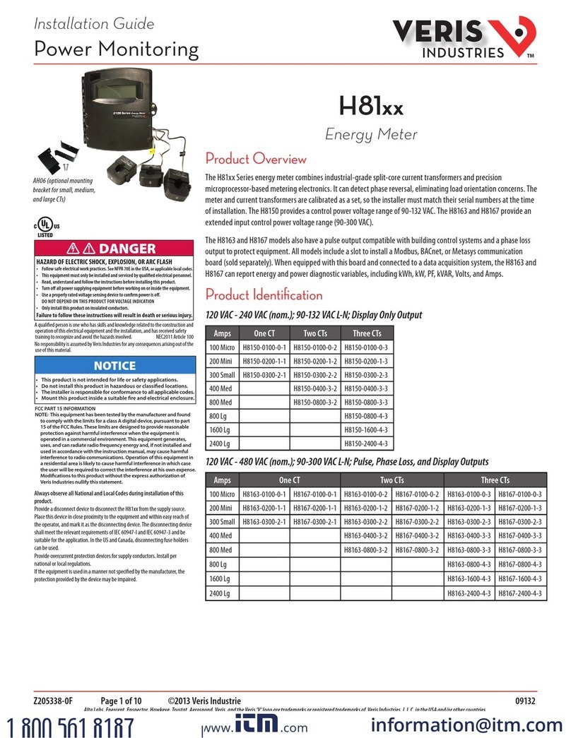
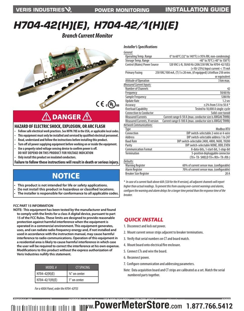
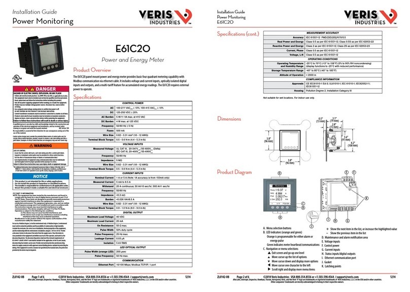
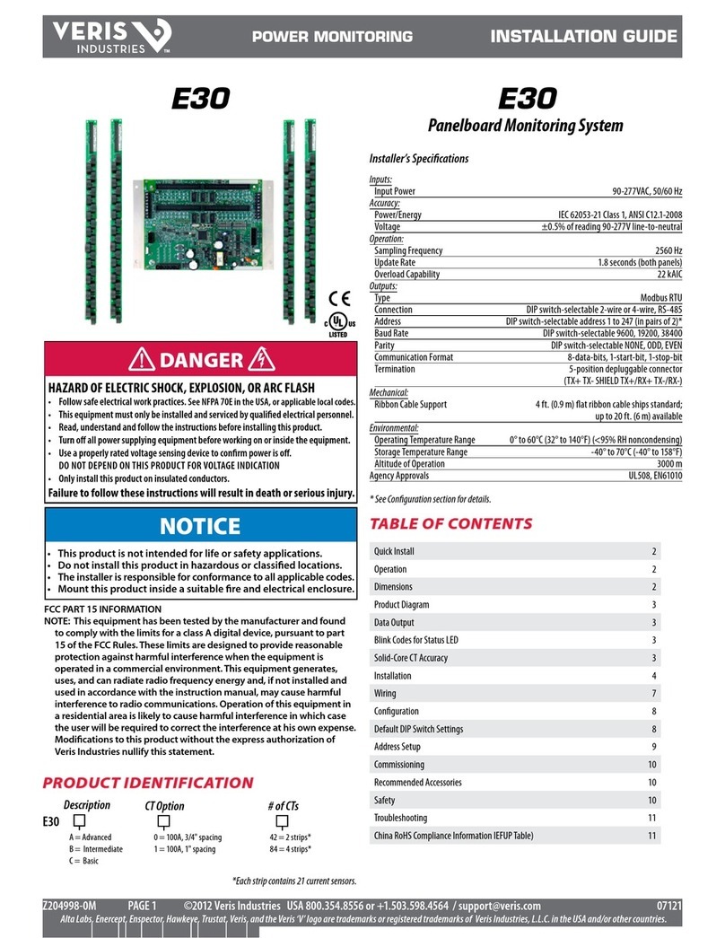
Product Identication
Product Overview
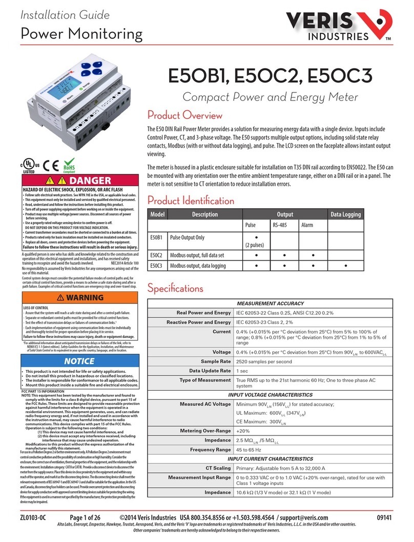
The H681x-V series of 1 volt and 0.333 volt split-core current transformers (CTs) provide secondary AC voltage
proportional to the primary (sensed) current. For use with power meters, data loggers, chart recorders, and other
instruments, the H681x-V series CTs provide a cost-eective means to transform electrical service amperages to a
voltage compatible with monitoring equipment.
H681x-V Series
Split-Core Current Transformers, Voltage Output
0.333 V Models Description
H6810-100A-.3V (R20) Split-Core CT, Small, 100A:0.333V
H6810-200A-.3V (R20) Split-Core CT, Small, 200A:0.333V
H6810-300A-.3V (R20) Split-Core CT, Small, 300A:0.333V
H6811-400A-.3V (R20) Split-Core CT, Medium, 400A:0.333V
H6811-600A-.3V (R20) Split-Core CT, Medium, 600A:0.333V
H6811-800A-.3V (R20) Split-Core CT, Medium, 800A:0.333V
H6812-800A-.3V (R20) Split-Core CT, Large, 800A:0.333V
H6812-1000A-.3V (R20) Split-Core CT, Large, 1000A:0.333V
H6812-1200A-.3V (R20) Split-Core CT, Large, 1200A:0.333V
H6812-1600A-.3V (R20) Split-Core CT, Large, 1600A:0.333V
H6812-2000A-.3V (R20) Split-Core CT, Large, 2000A:0.333V
H6812-2400A-.3V (R20) Split-Core CT, Large, 2400A:0.333V
H6810-100A-.3VU Split core CT, Small, .3V, 100A UL2808
H6810-200A-.3VU Split core CT, Small, .3V, 200A UL2808
H6810-300A-.3VU Split core CT, Small, .3V, 300A UL2808
H6810-400A-.3VU Split core CT, Small, .3V, 400A UL2808
H6811-600A-.3VU Split core CT, Medium, .3V, 600A UL2808
H6811-800A-.3VU Split core CT, Medium, .3V, 800A UL2808
H6812-1000A-.3VU Split core CT, Large, .3V, 1000A UL2808
H6812-1200A-.3VU Split core CT, Large, .3V, 1200A UL2808
H6812-1600A-.3VU Split core CT, Large, .3V, 1600A UL2808
H6812-2000A-.3VU Split core CT, Large, .3V, 2000A UL2808
H6812-2400A-.3VU Split core CT, Large, .3V, 2400A UL2808
H6812-800A-.3VU Split core CT, Large, .3V, 800A UL2808
1 V Models Description
H6810-100A-1V Split-Core CT, Small, 100A:1V
H6810-200A-1V Split-Core CT, Small, 200A:1V
H6810-300A-1V Split-Core CT, Small, 300A:1V
H6811-400A-1V Split-Core CT, Medium, 400A:1V
H6811-600A-1V Split-Core CT, Medium, 600A:1V
H6811-800A-1V Split-Core CT, Medium, 800A:1V
H6812-800A-1V Split-Core CT, Large, 800A:1V
H6812-1000A-1V Split-Core CT, Large, 1000A:1V
H6812-1200A-1V Split-Core CT, Large, 1200A:1V
H6812-1600A-1V Split-Core CT, Large, 1600A:1V
H6812-2000A-1V Split-Core CT, Large, 2000A:1V
H6812-2400A-1V Split-Core CT, Large, 2400A:1V
H6810-100A-1VU Split core CT, Small, 1V, 100A UL2808
H6810-200A-1VU Split core CT, Small, 1V, 200A UL2808
H6810-300A-1VU Split core CT, Small, 1V, 300A UL2808
H6810-400A-1VU Split core CT, Small, 1V, 400A UL2808
H6811-600A-1VU Split core CT, Medium, 1V, 600A UL2808
H6811-800A-1VU Split core CT, Medium, 1V, 800A UL2808
H6812-1000A-1VU Split core CT, Large, 1V, 1000A UL2808
H6812-1200A-1VU Split core CT, Large, 1V, 1200A UL2808
H6812-1600A-1VU Split core CT, Large, 1V, 1600A UL2808
H6812-2000A-1VU Split core CT, Large, 1V, 2000A UL2808
H6812-2400A-1VU Split core CT, Large, 1V, 2400A UL2808
H6812-800A-1VU Split core CT, Large, 1V, 800A UL2808
Subset of models shown.
E150462
E520136 E207042
Z202815-0Q Page 2 of 4 ©2021 Veris Industries USA 800.354.8556 or +1.503.598.4564 / suppor[email protected] 0621
12345 SW Leveton Drive, Tualatin OR 97062 USA
Alta Labs, Enercept, Enspector, Hawkeye, Trustat, Aerospond, Veris, and the Veris ‘V’ logo are trademarks or registered trademarks of Veris Industries, L.L.C. in the USA and/or other countries.
Other companies’ trademarks are hereby acknowledged to belong to their respective owners.
H681x-V Series Installation Guide
Specications
INPUTS
Frequency Range 50/60 Hz
Leads 6 ft (1.8 m)
20 ft (6 m)
ACCURACY
Accuracy ±1% of reading from 10% to 100% of rated current, specified with the
primary conductor(s) centered in the CT window
OUTPUTS
Output at Rated Current 1 V or 0.333 V
MECHANICAL
Insulation 600 Vac
ENVIRONMENTAL
Operating Temp Range 2400 A models only: -15 to 50 °C (5 to 122 °F);
All other models: -15 to 60 °C (5 to 140 °F)
Storage Temp Range -40 to 70 °C (-40 to 158 °F)
Humidity Range 0 to 95% non-condensing
Altitude of Operation 3 km max.
Mounting Location Not suitable for wet locations. For indoor use only.
WARRANTY
Limited Warranty 5 years
COMPLIANCE INFORMATION
Agency Approvals UL61010-1, IEC 61010-1, EN 61010-1
Installation Category Category III, Pollution Degree 2
INPUTS
Frequency Range 50/60 Hz
Leads 16 AWG, 8 ft (2.4 m), 20 ft (6 m)
ACCURACY
Accuracy These CTs meet or exceed accuracy requirements specified in IEC 61869-2,
Table 201, Class 1.
OUTPUTS
Output at Rated Current 1 V or 0.333 V
MECHANICAL
Insulation 600 Vac
ENVIRONMENTAL
Operating Temp Range -15 to 60 °C (5 to 140 °F)
Storage Temp Range -40 to 70 °C (-40 to 158 °F)
Humidity Range 0 to 95% non-condensing
Altitude of Operation 2 km max.
Mounting Location Not suitable for wet locations. For indoor use only.
WARRANTY
Limited Warranty 5 years
COMPLIANCE INFORMATION
Agency Approvals UL2808
Installation Category Category III, Pollution Degree 2
Split-Core
UL2808
Z202815-0Q Page 3 of 4 ©2021 Veris Industries USA 800.354.8556 or +1.503.598.4564 / suppor[email protected] 0621
12345 SW Leveton Drive, Tualatin OR 97062 USA
Alta Labs, Enercept, Enspector, Hawkeye, Trustat, Aerospond, Veris, and the Veris ‘V’ logo are trademarks or registered trademarks of Veris Industries, L.L.C. in the USA and/or other countries.
Other companies’ trademarks are hereby acknowledged to belong to their respective owners.
H681x-V Series Installation Guide
Installation Installation must be performed by a qualified electrician.
Disconnect and lock out power to the electrical panel.
1. Connect the secondary leads to the burden or test switching/shorting bar. The white wire is the x1 lead.
2. Depress the tabs on one end of the CT to open it. Check the core ends on both sections of the CT to ensure there is no rust or
debris in the closure areas.
3. Slip the CT over the primary leads. Note labeling on the product indicating “source side.”
H6810/Small UL2808
100 - 400 Amp
A = 3.23”(82 mm)
B = 1.4”(36 mm)
C = 1.4”(36 mm)
D = 1.12”(28 mm)
E = 3.25”(83 mm)
F = 4.12”(105 mm)
H6811/Medium UL2808
600 - 800 Amp
A = 4.95”(126 mm)
B = 2.9”(74 mm)
C = 2.46”(63 mm)
D = 1.2”(31 mm)
E = 5.36”(136 mm)
F = 5.83”(148 mm)
H6812/Large UL2808
1000 - 2400 Amp
A = 4.91”(125 mm)
B = 5.73”(146 mm)
C = 2.47”(63 mm)
D = 1.16”(30 mm)
E = 8.12”(206 mm)
F = 4.91”(125 mm)
B
E
F
CD
A
A
B
E
C
F
D
A
B
E
C
F
D
Dimensions Split-Core
UL2808
A
B
E
F
CD
B
E
F
CD
A
A
B
E
C
F
D
H6810
SMALL
100 Amp
200 Amp
300 Amp
H6811
MEDIUM
400 Amp
600 Amp
800 Amp
H6812
LARGE
800 Amp
1600 Amp
2000 Amp
2400 Amp
A = 3.8" (96 mm)
B = 1.5" (38 mm)
C = 1.3" (32 mm)
D = 1.1" (29 mm)
E = 3.9" (100 mm)
F = 4.8" (121 mm)
A = 4.9" (125 mm)
B = 2.9" (73 mm)
C = 2.5" (62 mm)
D = 1.1" (29 mm)
E = 5.2" (132 mm)
F = 5.9" (151 mm)
A = 4.9" (125 mm)
B = 5.5" (139 mm)
C = 2.5" (62 mm)
D = 1.1" (29 mm)
E = 7.9" (201 mm)
F = 5.9" (151 mm)
H6810/Small
100 - 300 Amp
A = 3.8”(97 mm)
B = 1.2”(31 mm)
C = 1.3”(32 mm)
D = 1.2”(31 mm)
E = 4.0" (102 mm)
F = 4.8" (122 mm)
H6811/Medium
400 - 800 Amp
A = 4.9”(125 mm)
B = 2.9”(74 mm)
C = 2.5”(64 mm)
D = 1.2" (31 mm)
E = 5.2”(132 mm)
F = 6.0" (152 mm)
H6812/Large
800 - 2400 Amp
A = 4.9”(125 mm)
B = 5.5”(140 mm)
C = 2.5”(64 mm)
D = 1.2”(31 mm)
E = 7.9" (201 mm)
F = 6.0" (152 mm)
Z202815-0Q Page 4 of 4 ©2021 Veris Industries USA 800.354.8556 or +1.503.598.4564 / suppor[email protected] 0621
12345 SW Leveton Drive, Tualatin OR 97062 USA
Alta Labs, Enercept, Enspector, Hawkeye, Trustat, Aerospond, Veris, and the Veris ‘V’ logo are trademarks or registered trademarks of Veris Industries, L.L.C. in the USA and/or other countries.
Other companies’ trademarks are hereby acknowledged to belong to their respective owners.
H681x-V Series Installation Guide
These products provide basic insulation to 600 Vac between the sensed conductor and the output leads. For reinforced
applications, the installer must provide appropriate insulation. Reinforced insulation is provided for applications to 300 Vac
between the sensed conductor and the output leads.
Ratings
4. Close and latch the CT, and mount it securely.
RISK OF INJURY OR EQUIPMENT DAMAGE/ RISQUE DE BLESSURE OU DE
DÉTÉRIORATION DE L’ÉQUIPEMENT
• Secure the I-bar to U-bar so that it remains in place. Close the CT with a suitable cable tie. / Fixer la barre
en I à la barre en U de sorte qu’elle reste fermement en place. Fermer leTC à l’aide d’un serre-câble
adapté.
Failure to follow these instructions may result in injury, fire or equipment damage. /
Le non-respect de ces instructions peut entraîner un risque de blessure, d’incendie ou
de détérioration de l’équipement.
WARNING/AVERTISSEMENT
Note: These split-core devices have a detachable I-bar. If the I-bar is removed, re-orient it according to the markings on the core
surface, then re-attach it. In any application where fault currents can exceed 20 times the rated current of the CT, use wire ties
or similar fasteners to secure both sides of the I-bar to the CT housing.
Note: The CTs except UL2808 require a single cable tie to secure the I-bar. Make sure to use the hole provided for cable tie. The
UL2808 100 - 400 A and UL2808 600 - 800 A CTs require a double cable tie. The UL2808 1000 - 2400 A CTs have a push-pin to
secure the I-bar and no cable tie is required.
5. Reconnect power to the panel.
Note: An optional mounting kit is available for these devices (Veris part number AH06).

This manual suits for next models

48

Other Veris Measuring Instrument manuals

Veris E50B1 User manual

Veris

Veris E50B1 User manual

Veris Enercept System Calibrated E20 Series User manual

Veris

Veris Enercept System Calibrated E20 Series User manual

Veris E30 series User manual

Veris

Veris E30 series User manual

Veris H8150-0100-0-1 User manual

Veris

Veris H8150-0100-0-1 User manual

Veris E30 series User manual

Veris

Veris E30 series User manual

Veris E51C2 User manual

Veris

Veris E51C2 User manual

Veris Enercept FLEX E20 Series User manual

Veris

Veris Enercept FLEX E20 Series User manual

Veris E61C20 User manual

Veris

Veris E61C20 User manual

Veris HW2 Series User manual

Veris

Veris HW2 Series User manual

Veris H81xx User manual

Veris

Veris H81xx User manual

Veris PX3 Series User manual

Veris

Veris PX3 Series User manual

Veris H704-42 User manual

Veris

Veris H704-42 User manual

Popular Measuring Instrument manuals by other brands

Biolin Scientific Q-sense E4 manual

Biolin Scientific

Biolin Scientific Q-sense E4 manual

Fluke PM6681 Service manual

Fluke

Fluke PM6681 Service manual

CoaguSense PT/INR user manual

CoaguSense

CoaguSense PT/INR user manual

Daiichi Electronics SVD-H-105 instruction manual

Daiichi Electronics

Daiichi Electronics SVD-H-105 instruction manual

ESD 94390 Operation, installation, and maintenance manual

ESD

ESD 94390 Operation, installation, and maintenance manual

APPA 103N user manual

APPA

APPA 103N user manual

D-tect Systems rad-DX Getting started guide

D-tect Systems

D-tect Systems rad-DX Getting started guide

Würth EASY FINDER Translation of the original operating instructions

Würth

Würth EASY FINDER Translation of the original operating instructions

Pepperl+Fuchs HART LUC-M Series operating instructions

Pepperl+Fuchs

Pepperl+Fuchs HART LUC-M Series operating instructions

Bosch vivatmo pro Instructions for use

Bosch

Bosch vivatmo pro Instructions for use

GHM Delta OHM HD3405.2 manual

GHM

GHM Delta OHM HD3405.2 manual

QUANTACHROME INSTRUMENTS MULTIPYCNOMETER manual

QUANTACHROME INSTRUMENTS

QUANTACHROME INSTRUMENTS MULTIPYCNOMETER manual

RC Electronics Raven manual

RC Electronics

RC Electronics Raven manual

BTEK T419S User instructions

BTEK

BTEK T419S User instructions

CESCO GlucCell Quick reference card

CESCO

CESCO GlucCell Quick reference card

Orange Research 1204 Series instruction manual

Orange Research

Orange Research 1204 Series instruction manual

ABB LS4000 operating instructions

ABB

ABB LS4000 operating instructions

Conrad TOOLCRAFT 2303985 operating instructions

Conrad

Conrad TOOLCRAFT 2303985 operating instructions

manuals.online logo
manuals.online logoBrands
  • About & Mission
  • Contact us
  • Privacy Policy
  • Terms and Conditions

Copyright 2025 Manuals.Online. All Rights Reserved.