Aerovent SCBD Series User manual
©2009 – 2022 Twin City Fan Companies, Ltd.
Aerovent Catalog 340 provides additional information on this equipment. This catalog can be found at www.aerovent.com or by contacting
your local Aerovent sales representative.
Nomenclature
SCBD - 120 A HP
SCBD = Belt Driven Centrifugal Inline
SCDD = Direct Drive Centrifugal Inline Design Vintage
Size
High Pressure
Throughout this manual, there are a number of HAZARD WARNINGS that must be read and adhered to in order to prevent possible
personal injury and/or damage to equipment. Two signal words "WARNING" and "CAUTION" are used to indicate the severity of a hazard
and are preceded by the safety alert symbol.
WARNING
Used when serious injury or death MAY result from misuse or failure to follow specific instructions.
CAUTION
Used when minor or moderate injury or product / equipment damage MAY result from misuse or failure to follow specific instructions.
NOTICE
Indicates information considered important, but not hazard-related.
It is the responsibility of all personnel involved in installation, operation and maintenance to fully understand the
Warning and Caution procedures by which hazards are to be avoided.
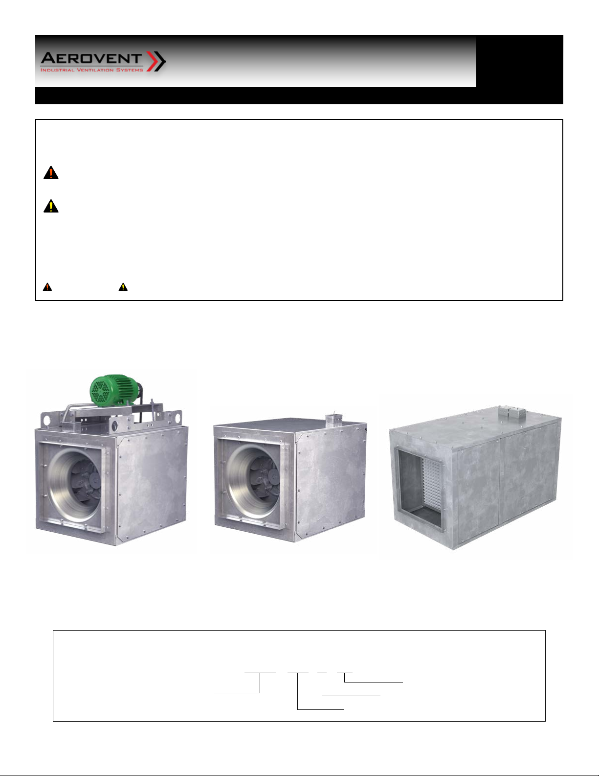
Model SCBD Model SCDD Model SCDD
– 080A through 402A – 080A through 165A Size 140X
IM-167
May 2020
Square Inline
Centrifugal Fans
General Installation, Operation and Maintenance Instructions For Aerovent Products
2 Aerovent Installation and Maintenance Manual IM-167
General Installation
The installation of this equipment shall be in accordance with the
regulations of authorities having jurisdiction and with all applicable
codes.
This equipment is to be installed by an experienced installation
company and fully trained personnel.
The mechanical installation of the inline centrifugal fan consists of
making final connections between the unit, building services and
duct connections.
Electrical Connection
1. Connect supply wiring to the disconnect switch (non-fused
standard). Check the wiring diagrams on the motor for
connections.
2. The motor is factory set at the voltage marked on the fan
nameplate. Check the line voltage with the nameplate voltage
and wiring diagrams.
3. The main power wiring should be sized for the ampacity
shown on the dataplate. Size wires in accordance with the
ampacitytablesinArticle310oftheNationalElectricalCode.
If long wires are required, it may be necessary to increase wire
size to prevent excessive voltage drop. Wires should be sized
for a maximum of 3% voltage drop.
4. Disconnectswitchesarenotfused.Thepowerleadsmustbe
protected at the point of distribution in accordance with the
fan dataplate.
5. On fans without a thermal protector integral to the motor
(refer to unit or motor dataplate to determine if protector
is present) a separate overload device is required. Refer to
Sections430-32oftheN.E.C.forsizing.
6. Allunitsmustbeelectricallygroundedinaccordancewithlocal
codes or, in the absence of local codes, with the latest edition
oftheNationalElectricalCode(ANSI/NFPA70).Agroundlugis
provided as standard in the unit terminal box. Size grounding
conductor in accordance with Table 250-95 of the National
ElectricalCode.DO NOT use the ground lug for connecting a
neutral conductor.
7. Supply voltage to the inline fan should not vary by more
than10%ofthevalueindicatedontheunitdataplate.Phase
unbalancemustnotexceed2%.
Sheet metal parts, screws, clips and similar items inherently have
sharp edges and it is necessary that the installer and service
personnel exercise caution.
CAUTION
Use copper conductors only.
CAUTION
Protect wiring from sharp edges. Leave some slack in the line
to prevent damage.
CAUTION
Failure of motor due to operation on improper line voltage
or with excessive phase unbalance constitutes product
abuse and may cause severe damage to the unit’s electrical
components.
WARNING
Receiving, Inspection & Unpacking
When the equipment is received all items should be carefully
checked against the bill of lading to be sure all crates and cartons
have been received. Before accepting delivery, carefully inspect
each carton or crate for visible shipping damage. If any damage is
noticed, the carrier should make the proper notation on the delivery
receipt acknowledging the damage. Make notations of all damage
on all copies of the bill of lading and have all copies countersigned
by the delivering carrier. The carrier should also fill out a Carrier
Inspection Report. The factory Traffic Department should then be
contacted.Fileclaimfordamagewiththecarrier.Physicaldamage
to the unit after acceptance is not the responsibility of Aerovent.
Unpack each carton or crate and verify that all required parts
and proper quantities of each item have been received. Refer to
drawings for part descriptions. Report shortages or missing items to
your local representative to arrange for replacement parts.
Due to availability of carriers and truck space, it is not possible to
guarantee that all items will be shipped together. Verification of
shipments must be limited to only those items on the bill of lading.
The unit nameplate must be checked to make sure the voltage
agrees with the power supply available.

Aerovent Installation and Maintenance Manual IM-167 3
Table 1. Impeller to Inlet Venturi
Check, Test & Start Procedure
1. Checktoverifythattheimpellerisfreetorotate.
2. For optimum fan performance make sure that the impeller to
inletventurioverlapismaintainted.SeeTable1.
3. Verify that supply voltage on the line side of disconnect agrees
withvoltageonfandataplateandiswithinthe10%utilization
voltage.
4. Apply power to unit and check rotation of impeller with the
directionalarrowontheunit.SeeTable2.
5. Electrical Input Check: Perform check of fan ampere draw and
verify that motor nameplate amps are not exceeded. Take into
account the service factor range if motor is nameplated above a
1.0servicefactor.
6. FanRPMshouldbecheckedandverifiedwithatachometer.
7. Units with Speed Control (Direct Drive): Verify that speed
controller gives desired operating range of RPM. If minimum
speed value is not desired, it may be adjusted. See page 4.
Table 2. Impeller Rotation*
* Impeller rotation is determined when viewed from discharge.
Note: On fans with three phase motors the impeller rotation can be
changed by reversing any two power leads.
Figure 1. Fan Impeller Rotation - View from Discharge
Note: CW rotation shown, CCW rotation is similar but opposite.
The fan was balanced at the factory to be within stringent
vibration levels before shipment. However, there are several
things that may cause vibration, such as rough handling in
shipment and installation, weak foundations and alignments.
NOTICE
MODEL OVERLAP
SCBD 0.50
SCDD 0.50
MODEL CW CCW
SCBD all ---
SCDD --- all
Electric shock hazard. Could cause severe injury or death. Failure to
bond the frame of this equipment to the building electrical ground
by use of the grounding terminal provided or other acceptable
means may result in electrical shock. Disconnect electric power
before servicing equipment. Service to be performed only by
qualified personnel. Before start-up, make sure power is turned
off and locked in the OFF position.
WARNING
Rotation is critical. If allowed to operate in the wrong direction,
the motor will overload and burn out.
WARNING
Check units for rotation. For three-phase, rotation can be
changed by interchanging any two of the three line leads. If
unit is checked on temporary wiring, it should be rechecked
when permanently installed. Motor burn-out or tripped
overload protection devices are usually the result of wrong
rotation.
WARNING
4 Aerovent Installation and Maintenance Manual IM-167
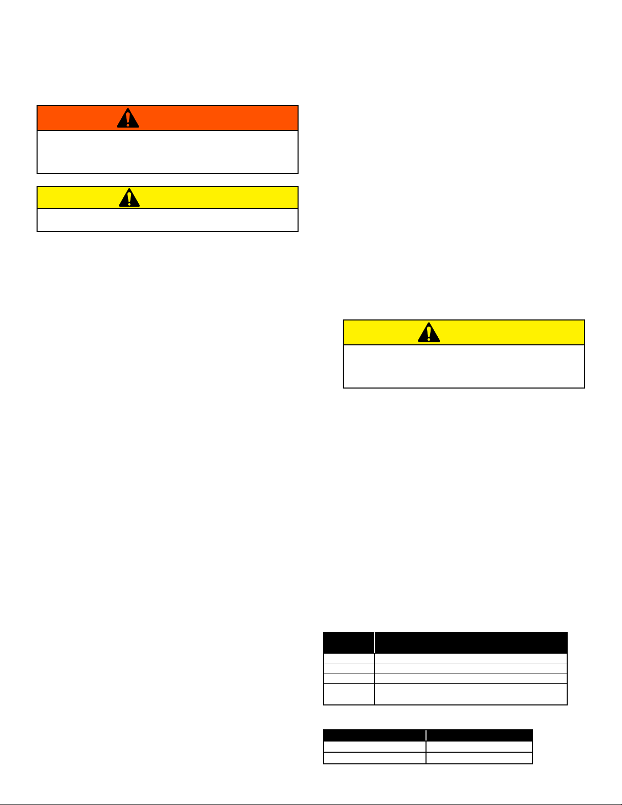
Figure 3. Low End Setpoint Adjustment
NOTE: 5ampmodelshown.On10and15ampmodels,
adjustment is made through clearance hole in heat sink.
SETPOINT
ADJUSTMENT
SCREW
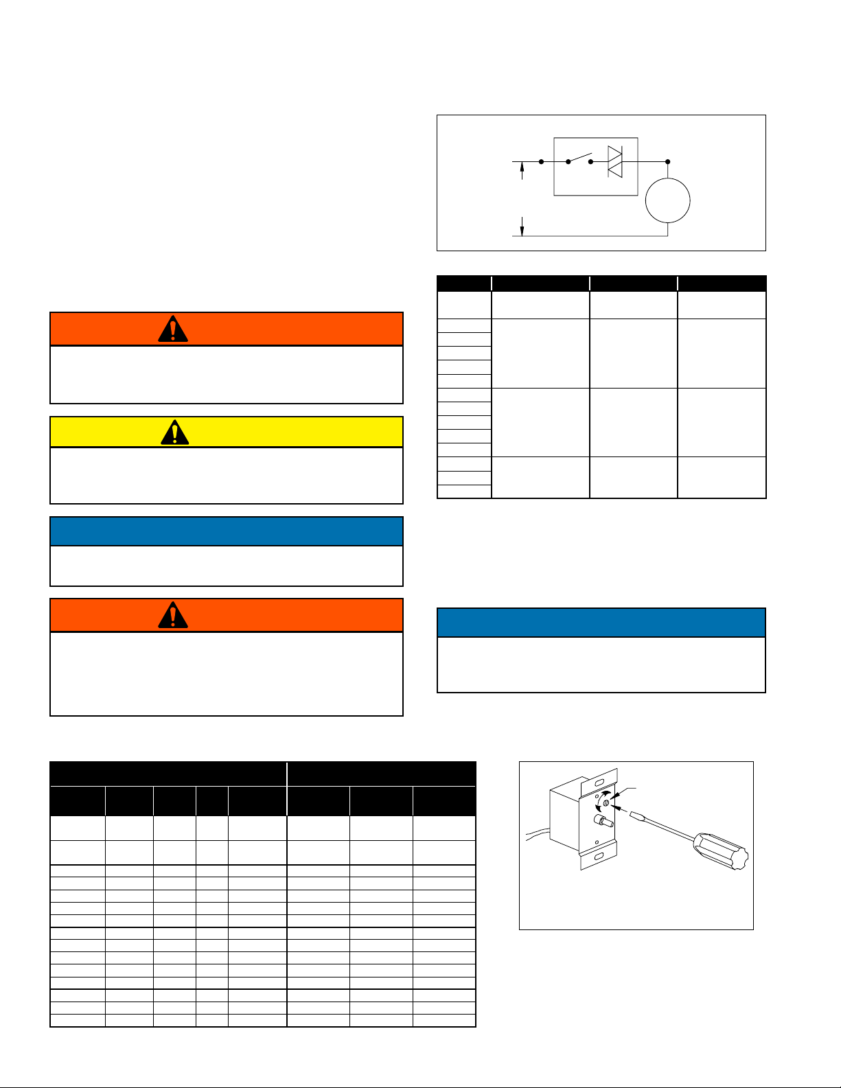
Table 4. Speed Controller Size
Speed Control Installation
(Model SCDD - optional)
Speed control is available for SCDD models using 115/60/1 open
type PSC or shaded pole motors.
Installation
Connect control in series with motor and line voltage (115V only).
Neverconnectacrossline.SeeFigure2.
Minimum Speed Setpoint
Allcontrolsarefactorysetto65V±3Voutputasstandardwithan
inputvoltage of 120V. If differentminimumspeedisdesired, the
control may be adjusted by turning minimum speed pot clockwise
to decrease minimum speed and counterclockwise to increase
minimumspeed.RefertoFigure3.
Figure 2. Connection Diagram, Speed Control
SPEEDCONTROLLER
AC
LINE
(115V)
SWITCH TRI-AC
MOTOR
Table 3. Speed Controller RPM Range
NOTES:
1. Speedcontrolavailableonlywith115/60/1openmotors(thermallyprotected).
2. Three-speedmotor(multipletapwinding).
3. Speed control should not be connected to low speed tap on motor because of
starting characteristics.
4. Speed control connected to high speed tap on motor.
5. Speed control connected to medium speed tap on motor.
MOTOR SPEED CONTROLLER
DESIGNATION / FLA"
PART
NUMBER
ENCLO-
SURE VOLTAGE HP RPM KBWC-15K
5 AMP
KBWC-110
10 AMP
KBWC-115
15 AMP
66801400 Open 115V 1/30 1650/1500/
1350 X
66543600 Open 115V 1/8 1650/1500/
1350 X
66804500 Open 115V 1/15 860 X
66543700 Open 115V 1/8 860 X
67123100 Open 115V 1/6 860 X
66543800 Open 115V 1/4 860 X
66543900 Open 115V 1/2 860 X
66804600 Open 115V 1/8 1140 X
67125100 Open 115V 1/6 1140 X
66544000 Open 115V 1/4 1140 X
66544100 Open 115V 1/2 1140 X
66544200 Open 115V 1 1140 X
66544300 Open 115V 1/3 1725 X
66544400 Open 115V 1/2 1725 X
67122500 Open 115V 3/4 1725 X
Lowering the minimum speed setpoint may adversely affect
motor start-up characteristics.
NOTICE
Do not allow any sleeve bearing motor to operate below 500
RPM. Operation below 500 RPM will substantially shorten
bearing life.
NOTICE
HP RPM MAX. RPM MIN. RPM
1/30 1650/1500/13502,3 1650413004
1/8 150059505
1/15
860 860 500
1/8
1/6
1/4
1/2
1/8
1140 1140 900
1/6
1/4
1/2
1
1/3
1725 1725 1200
1/2
3/4
If minimum speed is readjusted, verify unit ampere draw does
not exceed motor nameplate amps. Do not operate unit in range
where amp draw exceeds motor nameplate.
WARNING
These motors operate more efficiently in the ranges set from the
factory. Operating motor outside these ranges (see Table 3) may
cause motor to run hotter and substantially shorten motor life.
CAUTION
Certain failure modes of solid-state controls such as half-waving
can cause high levels of DC, motor overheating and motor burn-
out. Therefore, a thermal overload protection (integral with
motor) is required to limit the maximum motor temperature
under such a failure.
WARNING

Aerovent Installation and Maintenance Manual IM-167 5
Figure 4. Eliminate Slack Figure 5. Belt Deflection
Figure 6. Mounting Belts Figure 7. Sheaves
Figure 8. Belts
Deflection
Deflection = Belt Span
64
Belt Span
Slack belts wear excessively, cause slippage and
deliver less power. For longest belt life, always
provide proper tension
Mount belts straight. Shafts must be parallel and
sheaves in alignment to prevent unnecessary
belt wear.
Two-groove variable pitch sheaves
must be opened the same number
of turns on both sides; otherwise,
slippage occurs, wearing belts
rapidly.
Donotforcebelt.Forcingthebeltwillbreak
the cords and cause belt failure.
V-Belts
(Model SCBD)
V-belts on these belt driven fans are oil, heat and static resistant
type and oversized for continuous duty. With proper installation
and maintenance, years of operating efficiency can be added to the
lifespan of the V-belt drive.
The condition of V-belts and the amount of belt tension should be
checkedpriortostart-up(seeFigure4).Whenitbecomesnecessary
to adjust belt tension, do not over-tension as bearing damage will
occur. Recommended belt tension should permit 1⁄64" deflection
per inch of span of the belt at the center of the belt span. To find
this point, measure halfway between the pulley centerlines as
showninFigure5.Extremecaremustbeexercisedwhenadjusting
V-belts as not to misalign the pulleys. Any misalignment will cause a
sharp reduction in belt life and will also produce squeaky, annoying
noises (see Figure 6). On units equipped with 2 groove pulleys,
adjustments must be made so that there is equal tension on all
belts(seeFigure7).
1. Where tensioning rods are not provided, adjustment is more
easily obtained by loosening and adjusting one side of the motor
bracket at a time.
2. Always loosen tension adjustment enough to place belts on
sheaves without running belts over the edge of either sheave.
A new belt may be seriously damaged internally by careless
handling(seeFigure8).
3. Fan speed can be increased by closing the adjustable motor
pulley or decreased by opening it. Always check the load on the
motor when increasing the fan speed.
CORRECT
INCORRECT
When removing or installing belts, never force belts over
pulleys without loosening motor first to relieve belt tension.
WARNING

6 Aerovent Installation and Maintenance Manual IM-167
Fan Troubleshooting Chart
PROBLEM POSSIBLE CAUSES
FANDOESNOTOPERATE 1. Wrongvoltage.
2. Electricityturnedoffornotwiredproperly.
3. Trippedoverloadprotector.
4. Blownfuses.
5. Loosepulleys.
6. Brokenbelts.
TOOLITTLEAIR 1. Impellerrotatinginwrongdirection.
2. Fanspeedlowerthandesign.
3. Systemismorerestrictive(morestaticpressure)thanexpected.
4. Restrictedfaninletoroutlet.
5. Inletoroutletscreensclogged.
6. Filters(ifapplicable)aredirtyorclogged.
TOOMUCHAIR 1. Fanspeedhigherthandesign.
2. Systemislessrestrictive(lessstaticpressure)thanexpected.
3. Filters,ifapplicable,notinplace.
EXCESSIVEHORSEPOWER 1. Impellerrotatinginwrongdirection.
2. Impellerrubbingoninletventuri.
3. Fanspeedhigherthandesign.
4. Wornfanbearings.
EXCESSIVENOISE 1. Impellerorsheavesloose.
2. Bearingordrivemisalignment.
3. Accumulationofmaterialonimpeller.
4. Wornorcorrodedimpeller.
5. Impelleroutofbalance.
6. Impellerhittinghousing.
7. Bentshaft.
8. Bearingsneedlubrication.
9. Loosebearingbolts.
10. Looseorwornbearings.
11. Mismatchedbelts.
12. Beltstoolooseortootight.
13. Beltsoilyordirty.
14. Beltsworn.
15. Loosefanmountingbolts.
16. Rattleofcomponentsinhighvelocityairstream.
17. Electricalnoise.
18. Noisefromhighvelocityairsystem.
19. Vibratingpartsnotisolatedfrombuilding.
20. Vibratingductwork.
EXCESSIVEVIBRATION 1. Impellerorsheaveslooseonshaft.
2. Impelleroutofbalance.
3. Excessivebuildupofdirt/dustonimpeller.
4. Beltstoolooseortootight.
5. Mismatchedbelts.
6. Bentshaft.
7. Bearingordrivemisalignment.
8. Looseorwornbearings.
9. Fanmountingboltsloose.
10. Weakmountingbaseforfan.
11. Structuresnotcross-braced(wallfans).
12. Curbnotflatandlevel.
ItisrecommendedthattheusersandinstallersofthisshipmentfamiliarizethemselveswithAMCA Publication#201, “Fansand
Systems”andpublication#202,“Troubleshooting”whicharepublishedbytheAirMovementandControlAssociation(AMCA),30
WestUniversityDrive,ArlingtonHeights,Illinois60004.www.amca.org
Aerovent Installation and Maintenance Manual IM-167 7
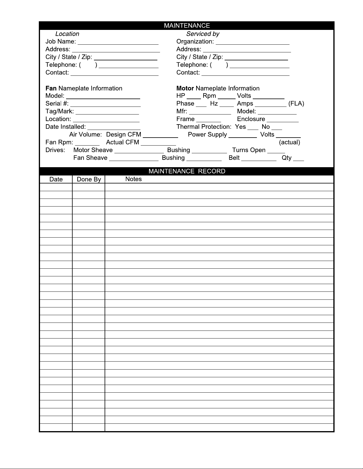
Maintenance
Installation and maintenance are to be performed only by qualified
personnel who are familiar with local codes and regulations and
experienced with this type of equipment.
Preventive maintenance is the best way to avoid unnecessary
expense and inconvenience. Routine maintenance should cover the
following items:
a. Tighten all set screws, bolts and wire connections.
b. Check belt tension and sheaves for wear.
c. Lubricatefanbearings(seeTables5and6).
d. Cleaningofunit,impelleranddamper(ifpresent).
All motors containing ball bearings are permanently lubricated
from the factory. No additional maintenance is required.
1 Beforeperforminganymaintenanceonthefan,be sure power
is turned off and locked in the OFF position at the service
entrance.
2. Fans should be carefully checked at least once a year. For
critical or rugged applications, a routine check every two or
three months is suggested.
3. For repairs within the warranty period, the motor must be
taken to the motor manufacturer’s authorized service dealer.
4. Aperiodicmotorcheckshouldconsistofspinningthemotor
shaft with the power off to be sure the motor turns freely and
the bearings run smoothly. The belt on belt driven units should
be removed from the motor sheave.
5. Whenremovingorinstallingabelt,donotforcethebeltover
thesheave.Loosenthemotormountsothatthebeltcanbe
easily slipped over the sheave.
6. Thebeltonbeltdrivenunitsshouldberemovedandcarefully
checked for glazing, cracks, ply separation or irregular wear. A
small irregularity in the contact surface of the belt will result in
noisy operation. If any of these defects are apparent, the belt
should be replaced. Check the sheaves also for chipping, dents
or rough surfaces, which could damage the belt.
7. Thecorrectbelt tension isimportant.Too tightofabeltwill
result in excess bearing pressure on the motor bearings and
shaft pillow blocks and may also overload the motor. Too loose
ofabeltwillresultinslippage,whichwillquickly“burn”out
belts.Abeltshouldfeel“live”whenthumped,approximately
1⁄4"beltdeflection(3to5lb.)whensubjecttofingerpressure
at midpoint between sheaves.
8. The belt alignment should also be checked to be sure the
beltisrunningperpendicularlytotherotatingshafts.Fanand
motor shafts must be parallel. Improper alignment will result
in excessive belt wear.
9. Checksheavesetscrewstoensuretightness.Properkeysmust
be in keyways.
10. Do not readjust fan RPM. If sheaves are replaced, use only
sheaves of identical size and type.
11. Ifunitistobeleftidleforanextendedperiod,itisrecommended
that belts be removed and stored in a cool, dry place to avoid
premature belt failure.
12. The standard pillow block bearings on belt driven fans are
factory lubricated and are provided with external grease fittings.
Lubrication annually is recommended or more frequently if
needed(seeTable5).
It is recommended to add fresh grease at start-up. Use only
2or3shotsofarecommendedlubricantwithahandgunin
mostcases (seeTable 6).Maximumhand gunrating40P.S.I.
Rotate bearings during lubrication where good safety practice
permits.
The most frequent causes of bearing failure are not
greasing often enough, using an excessive quantity of grease
or using incompatible greases. Excessive vibration, especially
if the bearing is not rotating, will also cause bearings to fail.
Bearings must also be protected from water and moisture to
avoid internal corrosion.
13. During the first fewmonths of operation it is recommended
that the bearing set screws be checked periodically to ensure
that they are tight.
14. The rotating impeller requires particular attention since
materials in the air being handled can build up on the blades
to cause destructive vibration or weaken the structure of the
impeller by corroding and/or eroding the blade metal. Regular
inspection and corrective action at intervals determined by the
severity of each application are essential to good service life
and safety.
INTERVAL TYPE OF SERVICE
(MONTHS)
12to18 Infrequentoperationorlightdutyincleanatmosphere.
6to12 8to16hrs./dayinclean,relativelydryatmosphere.
3to6 12to24hrs./day,heavyduty,orifmoistureispresent.
1to3 Heavy duty in dirty, dusty locations; high ambient
temperatures; moisture laden atmosphere; vibration.
Table 5. Suggested Fan Bearing Greasing Intervals
Table 6. Grease Manufacturers
MANUFACTURER GREASE (NLGI #2)
Shell ShellGadusS2V1002
Exxon/Mobil Ronex MP
Hazardous moving parts. Unit may contain protected fan motor,
which may start automatically and cause injury. Allow time for
reset. Disconnect power before servicing.
WARNING
Sharp edges and screws are a potential injury hazard. Avoid them.
CAUTION
Greases of different soap bases (lithium, sodium, etc.) may
not be compatible when mixed. Prevent such intermixing by
completely purging the bearing of old greases.
CAUTION
8 Aerovent Installation and Maintenance Manual IM-167
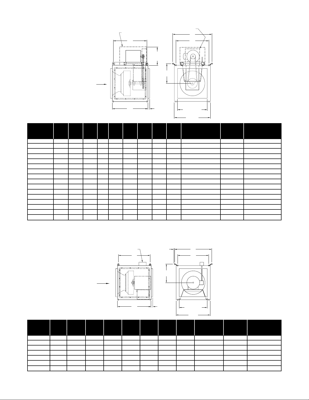
SCBD: Belt Driven Centrifugal Inline Fans
DIMENSIONSARENOTTOBEUSEDFORCONSTRUCTION.
MODEL DAMPER AVG. SHIP SIDE DISCHARGE
SCBD A B C D E F G H J SIZE WT. (LBS.) SIZE
080A 19.00 15.33 11.88 1.00 16.50 19.50 8.63 13.56 12.00 12.00x12.00 93 11.88x11.88
090A 19.00 15.33 11.88 1.00 16.50 19.50 8.63 13.56 12.00 12.00x12.00 96 11.88x11.88
100A 20.50 17.81 13.88 1.00 19.00 21.06 10.38 16.00 12.00 14.00x14.00 106 13.88x13.88
120A/120AHP 21.50 19.38 15.88 1.00 20.00 22.06 11.13 17.00 12.00 16.00x16.00 127 15.88x15.88
135A/135AHP 23.00 21.56 17.88 1.00 21.50 24.25 12.19 19.16 12.75 18.00x18.00 132 17.88x17.88
150A/150AHP 24.00 23.82 19.88 1.00 22.50 26.38 13.29 21.31 12.75 20.00x20.00 157 19.88x19.88
165A/165AHP 26.00 26.50 22.88 1.00 24.50 29.06 14.64 24.00 14.56 23.00x23.00 167 22.88x22.88
180A/180AHP 28.50 29.00 23.88 1.50 27.00 31.56 15.89 26.50 16.25 24.00x24.00 193 23.88x23.88
210A/210AHP 32.00 32.34 27.88 1.50 30.50 35.06 17.54 30.00 16.25 28.00x28.00 223 27.88x27.88
225A/225AHP 34.00 34.00 29.88 1.50 32.50 36.89 18.45 31.81 18.50 30.00x30.00 287 25.88x28.88
245A/245AHP 36.50 37.50 32.88 1.50 35.00 40.38 20.20 35.31 18.50 33.00x33.00 352 27.88x31.88
270A/270AHP 39.00 40.13 35.88 1.50 37.50 43.00 21.45 37.88 18.50 36.00x36.00 394 29.88x33.88
300A/300AHP 41.50 44.13 39.88 1.50 39.50 46.95 23.45 41.88 20.00 40.00x40.00 442 29.88x37.88
330A/330AHP 45.50 48.81 43.88 1.50 43.50 51.63 25.78 46.56 20.00 44.00x44.00 554 31.88x39.88
365A/365AHP 48.50 50.13 45.88 1.50 46.50 52.94 26.44 47.88 20.00 46.00x46.00 665 32.88x41.88
402A/402AHP 52.00 55.25 51.88 1.50 50.00 58.19 29.09 53.13 20.00 52.00x52.00 743 34.88x46.88
SCDD: Direct Drive Centrifugal Inline Fans
DIMENSIONSARENOTTOBEUSEDFORCONSTRUCTION.
MODEL
DAMPER AVG. SHIP SIDE DISCHARGE
SCDD A B C D E F G H SIZE WT. (LBS.) SIZE
080A 19.00 15.33 11.88 1.00 16.50 19.50 8.63 13.56 12.00x12.00 93 11.88x11.88
090A 19.00 15.33 11.88 1.00 16.50 19.50 8.63 13.56 12.00x12.00 96 11.88x11.88
100A 20.50 17.81 13.88 1.00 19.00 21.06 10.38 16.00 14.00x14.00 106 13.88x13.88
120A 21.50 19.38 15.88 1.00 20.00 22.06 11.13 17.00 16.00x16.00 127 15.88x15.88
135A/135AN 23.00 21.56 17.88 1.00 21.50 24.25 12.19 19.16 18.00x18.00 132 17.88x17.88
150A/150AN 24.00 23.82 19.88 1.00 22.50 26.38 13.29 21.31 20.00x20.00 157 19.88x19.88
165A/165AN 26.00 26.50 22.88 1.00 24.50 29.06 14.64 24.00 23.00x23.00 167 22.88x22.88
Aerovent Installation and Maintenance Manual IM-167 9
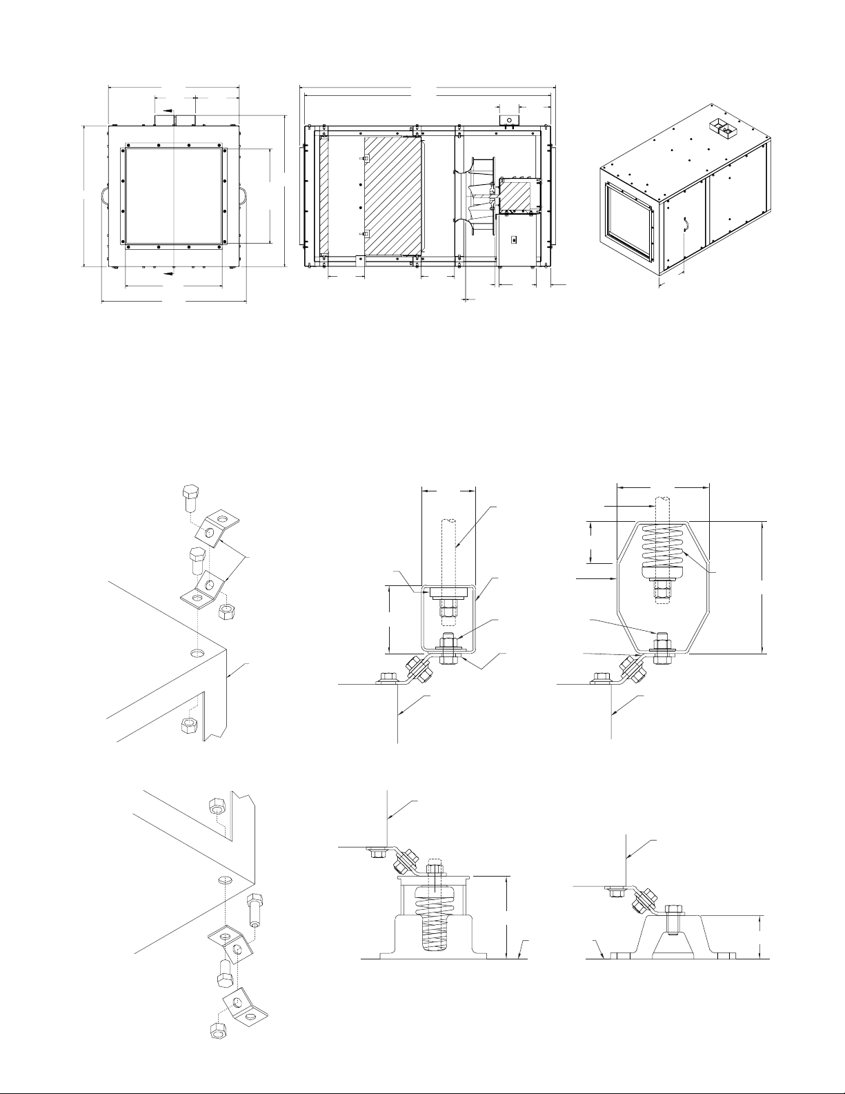
Mounting Brackets
SCBD and SCDD square inline fans can be mounted in any position:
horizontal, vertical or angular. They can be hung from above
or mounted on the floor. Typical dimensions (E and F) for the
mounting brackets that are supplied with these units are shown
on page 8. The 9⁄16" holes in these brackets can readily be used
for installing the units. To obtain optimum isolation, the SCBD unit
should be installed with the motor above or below the fan body.
Floor Mounting
Overhead Mounting
HANGER ROD, NUTS
& WASHERS
(NOT INCLUDED)
HANGER HOUSING
BOLT, NUTS &
WASHERS
(NOT INCLUDED)
HANGER BRACKET
SCBD/SCDD UNIT
NEOPRENE
ISOLATOR
2.72
2.15
5.25
3.69
3.00
SCBD/SCDD UNIT
SPRING
ISOLATOR
HANGER BRACKET
SCBD/SCDD UNIT
SCBD/SCDD UNIT
FINISHED FLOOR
SCBD/SCDD UNIT
3.50
1.50
SCDD, Size 140X with HEPA Filter: Direct Drive Centrifugal Inline Fans

10 Aerovent Installation and Maintenance Manual IM-167
Side Discharge Option
Sidedischargekits(includingpanels,mountingcollarsandnecessaryhardware)areavailabletoprovide1-way,2-wayor3-waydischarges.
Notes: Paneloppositemotor(onbeltedSCBD)cannotbeusedfordischarge.
NotavailableonModelSCDD140X.
INLET
INLET
INLET
LEFT
RIGHT
LEFT
RIGHT
INLET
LEFT
REAR
REAR
RIGHT
RIGHT
INLET
REAR
LEFT
FIG. B
FIG. G
FIG. E
FIG. F
FIG. C
FIG. D
INLET
Opon Figure Conguraon
Standard A Rear
1-Way BLe
C Right
2-Way
DLeandRight
E LeandRear
FRight and Rear
3-Way G Le,RightandRear
Configurations
INLET
REAR
Fig. A
Duct Openings
Model
SCBD
Model
SCDD
Le and Right Discharge Rear Discharge/Inlet
Duct Collar Duct Size
Required
Duct Collar Duct Size
Required
Width Height Width Height
080 080 11.88 11.88 12x12 11.88 11.88 12x12
090 090 11.88 11.88 12x12 11.88 11.88 12x12
100 100 13.88 13.88 14x14 13.88 13.88 14x14
120 120 15.88 15.88 16x16 15.88 15.88 16x16
135 135 17.88 17.88 18x18 17.88 17.88 18x18
150 150 19.88 19.88 20x20 19.88 19.88 20x20
165 165 22.88 22.88 23x23 22.88 22.88 23x23
180 —23.88 23.88 24x24 23.88 23.88 24x24
210 —27.88 27.88 28x28 27.88 27.88 28x28
225 —25.88 28.88 26x29 29.88 29.88 30 x 30
245 —27.88 31.88 28x32 32.88 32.88 33 x 33
270 —29.88 33.88 30 x 34 35.88 35.88 36x36
300 — 29.88 37.88 30x38 39.88 39.88 40 x 40
330 — 31.88 39.88 32x40 43.88 43.88 44 x 44
365 —32.88 41.88 33x42 45.88 45.88 46x46
402 —34.88 46.88 35x47 51.88 51.88 52x52
Side Discharge Instructions
SCREW, WHIZLOCK
SELF THREAD
#10 X 1/2 LG
OUTLET ANGLE
1/4-20 X 3/4
TAPTITE SCREW
ACCESS PANEL
NOTES:
1. Removeoutletanglesfromfandischarge.
2. Removeaccesspanelfromsiderequiredtobedischarge.
3. Mount outlet angles on new discharge.
4. Mountaccesspanelonbackoffan(previousoutlet).
Aerovent Installation and Maintenance Manual IM-167 11
Refertopage7forrecommendedmaintenance.

WWW.AEROVENT.COM
5959 Trenton Lane N | Minneapolis, MN 55442 | Phone: 763-551-7500 | Fax: 763-551-7501
Seller warrants to the original purchaser that the goods sold
hereunder shall be free from defects in workmanship and
materialundernormaluseandservice(exceptinthosecases
where the materials are supplied by the buyer) for a period of
oneyearfromthedateoforiginalinstallationoreighteen(18)
months from the date of shipment, whichever occurs first. The
liability of seller under this warranty is limited to replacing,
repairingorissuingcredit(atcost,F.O.B.factoryandatseller’s
discretion) for any part or parts that are returned by buyer
during such period provided that:
a. sellerisnotifiedinwritingwithinten(10)daysfollowing
discovery of such defects by buyer, or within ten (10)
days after such defects should reasonably have been
discovered, whichever is less;
b. the defective unit is returned to seller, transportation
charges prepaid by buyer.
c. payment in full has been received by seller for said
products; and
d. seller’s examination of such unit shall disclose to its
satisfaction that such defects have not been caused by
misuse, neglect, improper installation, repair, alteration,
act of God or accident.
No warranty made hereunder shall extend to any seller
product whose serial number is altered, effaced or removed.
Seller makes no warranty, express or implied, with respect to
motors, switches, controls or other components of seller’s
product, where such components are warranted separately by
theirrespectivemanufacturers.THISWARRANTYISEXPRESSLY
IN LIEU OF ALL OTHER WARRANTIES, EXPRESS OR IMPLIED,
WHETHER STATUTORY OR OTHERWISE, INCLUDING ANY
IMPLIED WARRANTY OF MERCHANTABILITY OR FITNESS FOR
A PARTICULAR PURPOSE. In no event shall seller be liable
to buyer for indirect, incidental collateral or consequential
damages of any kind. (BUYER’S FAILURE TO PAY THE FULL
AMOUNTDUEWITHIN SIXTY(60)DAYSOFDATEOFINVOICE
SHALL OPERATE TO RELEASE SELLER FROM ANY AND ALL
LIABILITY OR OBLIGATION ARISING PURSUANT TO ANY
WARRANTY, EXPRESS OR IMPLIED, WHETHER STATUTORY
OR OTHERWISE, INCLUDING ANY IMPLIED WARRANTY OR
MERCHANTABILITYORFITNESSFORAPARTICULARPURPOSE,
MADE IN CONNECTION WITH ANY CONTRACT FORMED
HEREUNDER. BUYER AGREES THAT SUCH FAILURE TO PAY
SHALL CONSTITUTE A VOLUNTARY WAIVER OF ANY AND ALL
SUCHWARRANTIESARISINGPURSUANTTOSUCHCONTACT.)
Limitation of Warranties and Claims
This manual suits for next models
61
Table of contents


