manuals.online logo
Brands
  1. Home
  2. •
  3. Brands
  4. •
  5. AES
  6. •
  7. Water Pump
  8. •
  9. AES Saci Optima Manual

AES Saci Optima Manual

This manual suits for next models

3

Other AES Water Pump manuals

AES XXS-3 User manual

AES

AES XXS-3 User manual

AES calpeda META User manual

AES

AES calpeda META User manual

AES MINI FOUL User manual

AES

AES MINI FOUL User manual

AES Baby Wipes Installation and user guide

AES

AES Baby Wipes Installation and user guide

Popular Water Pump manuals by other brands

Watershed Innovations HYDRAPUMP SMART FLEX Instructional manual

Watershed Innovations

Watershed Innovations HYDRAPUMP SMART FLEX Instructional manual

Graco Modu-Flo AL-5M instructions

Graco

Graco Modu-Flo AL-5M instructions

Messner MultiSystem MPF 3000 operating instructions

Messner

Messner MultiSystem MPF 3000 operating instructions

Xylem Bell & Gossett WEHT0311M Installation, operation and maintenance instructions

Xylem

Xylem Bell & Gossett WEHT0311M Installation, operation and maintenance instructions

WilTec 50739 Operation manual

WilTec

WilTec 50739 Operation manual

Franklin Electric Little Giant 555702 HRK-360S instruction sheet

Franklin Electric

Franklin Electric Little Giant 555702 HRK-360S instruction sheet

Ingersoll-Rand PD02P Series Operator's manual

Ingersoll-Rand

Ingersoll-Rand PD02P Series Operator's manual

VS ZJ Series Operating	 instruction

VS

VS ZJ Series Operating instruction

Flotec FPZS50RP owner's manual

Flotec

Flotec FPZS50RP owner's manual

SKF Lincoln FlowMaster II User and maintenance instructions

SKF

SKF Lincoln FlowMaster II User and maintenance instructions

Xylem Lowara LSB Series Installation, operation and maintenance instructions

Xylem

Xylem Lowara LSB Series Installation, operation and maintenance instructions

Water Duro Pumps DCJ500 Operating & installation instructions

Water

Water Duro Pumps DCJ500 Operating & installation instructions

Action P490 Operating instructions & parts manual

Action

Action P490 Operating instructions & parts manual

Flo King Permacore Reusable Carbon Bag Disassembly. & Cleaning Instructions

Flo King

Flo King Permacore Reusable Carbon Bag Disassembly. & Cleaning Instructions

ARO ARO PD15P-X Operator's manual

ARO

ARO ARO PD15P-X Operator's manual

Pumptec 112V Series Operating instructions and parts manual

Pumptec

Pumptec 112V Series Operating instructions and parts manual

Virax 262070 user manual

Virax

Virax 262070 user manual

Neptun NPHW 5500 operating instructions

Neptun

Neptun NPHW 5500 operating instructions

manuals.online logo
manuals.online logoBrands
  • About & Mission
  • Contact us
  • Privacy Policy
  • Terms and Conditions

Copyright 2025 Manuals.Online. All Rights Reserved.

MANUAL DE INSTALACION Y MANTENIMIENTO
INSTALLATION AND MAINTENANCE MANUAL
MANUEL DINSTALLATION ET DENTRETIEN
INSTALLATIONS UND WARTUNGSANLEITUNG
MANUALE DI INSTALLAZIONE E MANUTENZIONE
NÁVOD K INSTALACI A ÚDRB
MANUAL DE INSTALAÇÃO E MANUTENÇÃO
MONTAJ VE BAKIM TAL MAT EL K TABI
'EX'3;
6IZ
0845 803 5581 | [email protected]
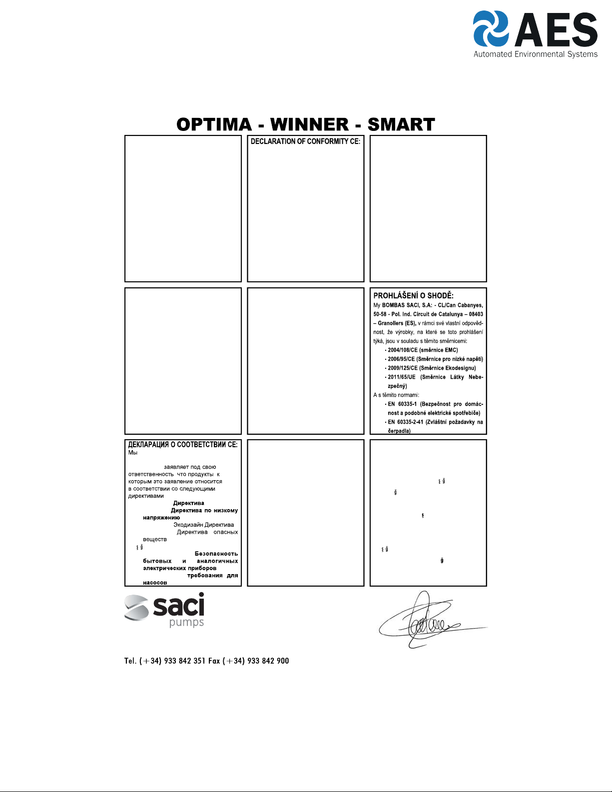
DECLARACION DE CONFORMIDAD CE:
Nosotros, BOMBAS SACI, S.A., CL/Can Cabanyes,
50-58 - Pol. Ind. Circuit de Catalunya 08403 
Granollers ESPAÑA, declaramos bajo nuestra exclusiva
responsabilidad que los productos a los que se refiere esta
declaración son conformes con las directivas siguientes, y
posteriores revisiones:
- 2004/108/CE (Directiva Compatibilidad Electro-
magnética)
- 2006/95/CE (Directiva de bajo voltaje)
- 2009/125/CE (Directiva Diseño Ecológico)
- 2011/65/UE (Directiva Sustancias Peligrosas)
y también cumples las normas siguientes:
- EN 60335-1 (Seguridad de los aparatos electrodo-
mésticos y análogos)
- EN 60335-2-41 (Requerimientos particulares para
bombas)
We, BOMBAS SACI, S.A., CL/Can Cabanyes, 50-58 -
Pol. Ind. Circuit de Catalunya 08403 Granollers
SPAIN, state that under our exclusive responsibility
the products referred to in this statement comply with the
following directives and subsequent revisions:
- 2004/108/EC (Electromagnetic Compatibility
Directive)
- 2006/95/EC (Low Voltage Directive)
- 2009/125/EC (Ecologic Design Directive)
- 2011/65/EU (Dangerous Substances Direc-
tive)
and that they also comply with the following regulations:
- EN 60335-1 (Household and Similar Electrical
Appliances Safety)
- EN 60335-2-41 (Particular Requirements
for Pumps)
DÉCLARATION DE CONFORMITÉ CE:
Nous, BOMBAS SACI, S.A., CL/Can Cabanyes, 50-58 -
Pol. Ind. Circuit de Catalunya 08403 Granollers
ESPAGNE, déclarons sous notre responsabilité exclusive
que les produits auxquels cette déclaration fait référence
sont conformes aux directives suivantes et à leurs révisions
postérieures :
- 2004/108/CE (Directive CEM)
- 2006/95/CE (Directive Basse Tension)
- 2009/125/CE (Directive Eco-Conception)
- 2011/65/UE (Directive Substances Dange-
reux)
Et qu’ils respectent aussi les normes suivantes :
- EN 60335-1 (Sécurité des appareils électro-
domestiques et analogues)
- EN 60335-2-41 (Règles particulières pour
les pompes)
Can Cabanyes, 50-58 - Pol. Ind. Circuit de Catalunya
08403 Granollers Spain
www.sacipumps.com - [email protected]
(EZMH*IVVÍ*IVVIV
)<)'98-:)
KONFORMITÄTSERKLÄRUNG CE:
Wir, BOMBAS SACI, S.A: - CL/Can Cabanyes, 50-58 -
Pol. Ind. Circuit de Catalunya 08403 Granollers
(E), erklären unter unserer Verantwortung, dass Erzeug-
nisse, auf die sich diese Erklärung bezieht in Übereinstim-
mung mit folgenden Richtlinien sind:
- 2004/108/CE (EMV-Richtlinie)
- 2006/95/CE (Niederspannungsrichtlinie)
- 2009/125/CE (Ökodesign-Richtlinie)
- 2011/65/UE (Richtlinie über gefährliche
Stoffe)
Und mit den folgenden Standards:
- EN 60335-1 (Sicherheit von Haushalts-und
ähnlichen Elektrogeräten)
- EN 60335-2-41 (Besondere Anforderungen
für Pumpen)
DICHIARAZIONE DI CONFORMITA CE:
Noi BOMBAS SACI, S.A: - CL/Can Cabanyes, 50-58 -
Pol. Ind. Circuit de Catalunya 08403 Granollers
(ES), dichiariamo sotto la nostra esclusiva responsabilità
che i prodotti ai quali questa dichiarazione si riferisce sono
conformi alle seguenti direttive:
- 2004/108/CE (Direttiva EMC)
- 2006/95/CE (Direttiva Bassa Tensione)
- 2009/125/CE (Direttiva Progettazione Eco-
compatibile)
- 2011/65/UE (Direttiva Sostanze Dangerous)
E con le seguenti norme:
- EN 60335-1 (Sicurezza di elettrodomestici e
apparecchi elettrici)
- EN 60335-2-41 (Norme particolari per le
pompe)
,BOMBAS SACI, S.A: - CL/Can Cabanyes,
50-58 - Pol. Ind. Circuit de Catalunya 08403
Granollers (E),
, ,
:
- 2004/108/CE ( EMC)
- 2006/95/CE (
)
- 2009/125/CE ( )
- 2011/65/UE (
)
Ve a a×daki standartlara:
- EN 60335-1 (
)
- EN 60335-2-41 (
)
DECLARAÇÃO DE CONFORMIDADE CE:
Nós, BOMBAS SACI, S.A: - CL/Can Cabanyes, 50-58 -
Pol. Ind. Circuit de Catalunya 08403 Granollers
(E), declaramos sob nossa responsabilidade que os produ-
tos a que se refere esta declaração estão em conformidade
com as seguintes diretrizes:
- 2004/108/CE (Directiva CEM)
- 2006/95/CE (Directiva de Baixa Tensão)
- 2009/125/CE (Directiva Ecodesign)
- 2011/65/UE (Directiva Substâncias Dange-
rous)
E com as seguintes normas:
- EN 60335-1 (Segurança em casa e aparelhos
elétricos similares)
- EN 60335-2-41 (Prescrições particulares para
bombas)
UYGUNLUK CE OF BEYANI:
Biz, BOMBAS SACI, S.A: - CL/Can Cabanyes, 50-58 -
Pol. Ind. Circuit de Catalunya 08403 Granollers
(E), bu beyan eder hangi ürünleri a a×daki yönetmeliklere
uygun oldu unu bizim sorumluluk alt×nda beyan ederiz:
- 2004/108/CE (EMC Direktifi)
- 2006/95/CE (Dü ük Voltaj Direktifi)
- 2009/125/CE (Eko-tasar×m Direktifi)
- 2011/65/UE (Tehlikeli Maddeler Direktifi)
Ve a a×daki standartlara:
- EN 60335-1 (ev güvenli i ve benzeri elek-
trikli ev aletleri)
- EN 60335-2-41 (pompalar için özel kurallar)
Granollers, a 1 de Noviembre de 2016
0845 803 5581 | [email protected]
15
INSTALLATION AND MAINTENANCE MANUAL
(Instructions based on Spanish)
1. SAFETY PRECAUTIONS
This symbol together with one of the following words Warningor Dangerindicates the risk level deriving from
failure to observe the prescribed safety precautions:
DANGER risk of electric shock (Warns that failure to observe the precautions involves a risk of
electric shock)
DANGER (Warns that failure to observe the precautions involves a risk of damage to persons or
things)
WARNING (Warns that failure to observe the precautions involves a risk of damaging the pump or
the instalation)
2. WARNINGS
Before carrying out the installation, please read this instruction manual carefully.
It is essential that both the electrical installation and the connections are performed by qualified personnel,
who possess the required technical expertise required by the specific safety regulations for the project,
installation and maintenance of the technical installations for the country where the product is to be installed.
Any non-compliance with the safety regulations, in addition to being a danger to personnel and causing damage to
the equipment, will cancel all rights to interventions covered by the guarantee.
- The device is not designed for use by persons (including children) with physical, sensory or mental capabilities, or
lack of experience and knowledge, unless they are supervised and instructed by a person responsible for their safety.
- Children should be supervised to ensure they do not play with the appliance.
3. APPLICATIONS AND USE
Self-induction electric pump for swimming pools, incorporating large capacity pre-filter with high filtration capability.
Transparent, polycarbonate filter cover allowing easy observation of the inside of the pre-filter basket.
Our pumps have been developed for continuous operation and the materials used in their manufacture are subjected
to strict controls and are rigorously verified.
The machine has been designed to pump water that is free from explosive substances, with a density equivalent to 1000
Kg/m3and a kinematic viscosity of 1 mm2/s, as well as chemically non-aggressive liquids.
It has no uses other than the one previously described.
4. TECHNICAL DATA AND LIMITATIONS OF USE
Power supply voltage: Single-phase, 230 V, 50/60 Hz. See data plate
Three-phase, 230 - 400 V, 50/60 Hz.
Motor Protection: IP 55
Insulation class: Class F
MAXIMUM ENVIRONMENTAL TEMP.: +40ºC
MAXIMUM PUMPED LIQUID TEMP.: +40ºC
5. TRANSPORT
Do not subject the products to unnecessary bumps and knocks.
When lifting and transporting the unit, use machines and tools that have been designed for this purpose, using the
pallet supplied as standard (if present).
0845 803 5581 | [email protected]
16
3/
23
6. STORAGE
All the pumps should be stored in a sheltered, dry, dust-free place, with regulated air-moisture levels when possible.
The pumps are supplied in their original packaging, where they must remain until assembly.If not, keep the suction
and discharge ports closed.
7. INSTALLATION
General
The pump should be installed as close as possible to the level of water, leaving a minimum of two metres to
the swimming pool edge in accordance with IEC publication No. 364 in a horizontal position, in order to obtain
minimum run length in suction and a reduction of load losses.
Sufficient space should be allowed for removing to pre-filter basket for cleaning and re-fitting.
The pump should be installed on a solid, very smooth surface. It is necessary to perfectly fit the pump through the two
holes provided for this purpose in the support base by means of two screws or other similar methods to prevent any
possible noise or vibration that could adversely affect the pump operation.
The pump should not be installed at a geometric height of more than 3.5 metres above the water level.
In order to obtain optimum pump self-priming, it should be installed at a maximum of 2.5 metres above the water
level.
The pump should be protected from any possible flooding and correct ventilation should be ensured, but without
risking the effects of freezing. In the case of outside installation, the pump should be protected from rain and a power
supply cable in accordance with EEC standards, type H07-Requirement Number-F (in accordance with VDE 0250)
should be installed. The pump is normally supplied without an electric power cable. In this case the pump test cables
can be seen to be cut at the outlet of the motor junction box. These cables must be replaced by a suitable electric hose
in accordance with the legislation in force in each country.
In the case of being installed a fibre housing, whether buried or half-buried, sufficient air flow should be guaranteed
to generate correct ventilation that prevents the maximum interior temperature from exceeding 40ºC.
Assembling the Piping
We recommend the installation of cut-off valves in both pump suction and impulsion so that the pump may
be removed from the installation without having to empty the whole circuit first.
The suction piping should be at least the same diameter as the pump connection, and it is also recommended that the
impulsion piping should also be the same diameter as the pump connection.
The suction piping should be assembled with a slight inclination towards the pump to prevent air pockets forming
inside.
0845 803 5581 | [email protected]
17
3~
230 V 400 V
1~
It is very important that both the suction and impulsion piping are independently supported and correctly fixed in place
so that the pump does not have to support their weight nor the vibration produced by the water flow though them. In
a situation where a long length of impulsion piping is used, we recommend the installation of a check valve to prevent
the water hammer produced by the return of the water causing any damage when the pump stops.
If flexible piping is employed, it should be the non-compressible type.
When making the connections to the pump, totally clean connections should always be used, with the thread in perfect
conditions and leak-tightness should be obtained only through the use of Teflon tape, (glues or similar products should
not be employed). These connection should be slowly tightened, with special care not to strip the internal thread of
the pump by over-tightening.
8. ELECTRICAL CONNECTION
Before carrying out any maintenance on the electrical part of the motor, it should be disconnected from the
electricity supply.
System protection should be based on a differential breaker (Ifn = 30 mA). A GOOD EARTH CONNECTION MUST
BE MADE WHENEVER POSSIBLE. The earth terminal, in particular, must be connected to the yellow/green conductor
of the supply cable. An earth conductor that is longer than the phase conductors must also be used so as to prevent it
from being the first to disconnect if pulled.
All our single-phase motors incorporate thermal protection that will disconnect the pump if the motor temperature
increases due to an overload and will then connect the electricity supply again once the temperature has dropped to
within normal levels again.
For three-phase versions, the user should provide appropriate protection in accordance with current regulations.
It is essential to connect the pump to a suitable ground.
The following diagram, should be used when making the electrical connections to the pump terminals.
Use is only permitted if the electric installation has safety protection systems in accordance with personal safety
regulations in force in the country where the product is to be installed.
0845 803 5581 | [email protected]
18
9. CHECKS PRIOR TO PUTTING INTO SERVICE
THE PUMP SHOULD NEVER BE ALLOWED TO OPERATE OFF LOAD
Check that the voltage and frequency of the incoming mains electricity supply correspond to those on the pump’s
specification plate.
Unscrew the transparent pre-filter cover and fill the pre-filter with water until the water level reaches the suction hole.
Replace the pre-filter cover and hand-tighten only, ensuring that it is fully tightened.
Check the pump shaft is able to freely rotate.
Check the that the direction of motor rotation corresponds with that indicated on the
specification plate (the fan should rotate in a CLOCKWISE DIRECTION, when viewed from
the rear of the motor. If the motor is three-phase and it is observed that it is rotating in
the opposite direction, then two of the supply phases should be inverted at the protection
panel.
10. PUTTING INTO SERVICE
Open all valves, both suction and impulsion, and switch on the pump.
Wait a reasonabletime for the pump and suction piping to self-prime. If this takes too long, then the priming
process should be repeated.
Once the pump has correctly self-primed and the pre-filter body is seen to be full of water, the motor current should
be checked and the thermal relay adjusted appropriately.
11. MAINTENANCE, DISMANTLING AND RECYCLING
The most important maintenance operation is that of keeping the pre-filter basket clean, and this filter state
check should be performed after each filtration operation and especially after bottom-cleaning. The procedure
is as follows:
Disconnect the electricity supply to the pump. Close the suction and impulsion valves to the pump. Open the pre-filter
cover, remove the basket and clean it. Once it is clean, replace it, but before closing, check the condition of the pump
body thread, pre-filter cover and the O-ring, cleaning them only with water, and where necessary apply a light coating
of neutral Vaseline.
The pump should only be dismantled by qualified personnel who hold the technical qualifications required under the
technical safety regulations of the country where the product is located.
This product and its components must be disposed of in accordance with environmental regulations. Use local public
or private waste-collection systems.
0845 803 5581 | [email protected]
19
Under no circumstances should chlorine tablets be placed in the pre-filter basket.
The special key that is supplied to OPEN the pre-filter cover, should never be employed to close it.
When there is a frost risk, or when the pump is to remain off for any significant length of time, then it should
be emptied. This is accomplished by removing the two emptying plugs on the lower part of the pump body.
Apart from what has been stated above, our pumps do not require any other maintenance operations since the
bearings have been dimensioned and lubricated for life.
POSSIBLE FAULTS, THEIR CAUSES AND SOLUTIONS
• The pump will not prime
• The pump has not been primed
• Air entering by the suction piping
• Air entering via the mechanical seal
• Incorrectly closed pre-filter cover
• Excessive suction height
• Inverted motor rotation
• Incorrect voltage
• Air entering by the suction piping.
• Excessive suction height.
• Inverted motor rotation.
• Incorrect voltage.
• Blocked
• Suction piping diameter is less than
that required.
• Impulsion closed or blocked.
• Suction piping diameter is less than
that required.
• The pump or piping has not been
correctly secured.
• Inverted motor rotation
• Lack of mains supply.
• Breaker operation.
• Incorrect voltage.
• Motor jammed.
• Fill the pre-filter with water.
• Check the connections and piping.
• Replace the mechanical seal.
• Close correctly.
• Install at a suitable height.
• Invert two of the motor phases.
• Check the plate voltage.
• Check the connections and piping.
• Install at a suitable height.
• Invert two of the motor phases.
• Check the plate voltage.
• Clean the pre-filter basket.
• Correctly dimension the suction piping.
• Open the valve and check the sand
filter condition.
• Correctly dimension the suction piping.
• Recheck the pump and piping securing
methods so that they are separate.
• Invert two of the motor phases
• Check the voltage and fuses.
• Check and reset breaker.
• Check the plate voltage.
• Consult the Official Technical Service.
• The pump provides a poor flow rate
• The pump makes a lot of noise
• The pump will not start
FAULTS CAUSES SOLUTIONS
0845 803 5581 | [email protected]
20
12.1. SAFETY RULES
Before installing and using the product:
-Carefully read the whole of this manual
-The installation and maintenance must be carried out solely and exclusively by authorised personnel, responsible
for making the electrical connections in accordance with current safety regulations.
-The frequency converter must not be used by people with reduced physical, sensory or mental capabilities,
or without the due experience or knowledge, except if a person responsible for their safety has explained the
instructions and supervised their operation of their frequency converter.
-Do not let children play with the frequency converter.
-The manufacturer accepts no liability for damage caused by improper use of the product and shall not be held
responsible for damage caused by maintenance or repairs carried out by unqualified staff and/or using non-
original replacement parts.
-The use of unauthorised replacement parts, alterations of the product or improper use shall automatically render
the product guarantee null and void.
During normal operation:
-Before removing the cover of the controller for any maintenance work, ensure you disconnect the mains voltage.
-Never electrically disconnect the controller while the motor is rotating. This action may cause irreparable damage
to the electronics of the controller.
-Even if the motor is not turning (RUN LED off), the electrical supply must still be cut off for any maintenance
work.
SWIMMING POOL PUMP CONTROLLER
0845 803 5581 | [email protected]
21
12.2. TECHNICAL DATA
Nominal values:
12.3. INSTALLATION AND ASSEMBLY
Before installing the pump with time controller, carefully read the whole of this manual and consult the safety rules
valid in each country.
The authorised installer must consider the following indications:
-It must be installed in a well-ventilated area, protected against moisture and direct exposure to the sun and rain.
-Before making the electrical connections, ensure the cable used to provide power to the frequency converter is
not live.
-The electric power cables to the controller must be of the correct size for the nominal consumption of the pump
and the length of cable required.
12.4. ELECTRICAL CONNECTIONS
Output pump
(220V – 16A max.)
External intakeChlorinator outletLight outlet
Power supply
(220V – 50/60Hz)
0845 803 5581 | [email protected]
22
12.5. SCREEN FORMAT
12.6. MAIN SCREEN
Main screen
Centre
selection button
Left
selection button
Manual operation
Current time
S
:
aM
7
tnu
61
t
4
re
we
Day of the week
Right
selection button
Access to the menu
Power LED
Pump
operational LED
Fault LED
Manual
lights button
12.7. OPERATION MODE
The swimming pool pump’s intelligent controller eliminates electrical panel installation requirements for the pump’s
automatic start-up, the lights, etc. in domestic installations, and includes other functions and protection elements that
a conventional electrical panel does not have.
Its main features are:
-Very intuitive QuickStart assistant for the basic configuration of the unit.
-Timer control activation/deactivation of the swimming pool pump, with three configurable daily cycles and with
the possibility to select the days of the week on which filtration is required.
-Timer control for activating the swimming pool lights, and other programmable timing applications. This function
also enables configuration of the days of the week on which the lights will be activated.
0845 803 5581 | [email protected]