Aesthetix METIS Linestage User manual

Aesthetix Audio Corporation
5220 Gabbert Rd., Suite A Moorpark, CA. 93021
Phone: (805) 529-9901
M E T I S
Linestage
Owner’s Manual

2
The lightning flash with arrowhead symbol, within an equilateral triangle,
is intended to alert the user to the presence of un-insulated “dangerous
voltage” within the product’s enclosure that may be of significant
magnitude to constitute a risk of electric shock to persons.
The exclamation point within an equilateral triangle is intended to alert
the user to the presence of important operating and maintenance
(servicing) instructions in the literature accompanying the product.
WARNING
TO REDUCE THE RISK OF FIRE OR ELECTRIC SHOCK,
DO NOT EXPOSE THIS PRODUCT TO RAIN OR MOISTURE
CAUTION: TO PREVENT ELECTRIC SHOCK, DO NOT USE THE AC (POLARIZED) PLUG WITH AN
EXTENSION CORD, RECEPTACLE OR OTHER OUTLET UNLESS THE BLADES CAN BE FULLY INSERTED
TO PREVENT BLADE EXPOSURE.
Extension cords are not recommended for use with this product.

3
PREFACE
INTRODUCTION
This manual covers the use of the Metis, using references to the hand held remote which has
a separate owner’s manual.
Thank you for purchasing the Metis Line Preamplifier. It has been engineered to deliver the
highest attainable sound quality. This is its sole purpose. Only the highest grade electronic
components are used in the Metis, including: non-inductive Roederstein metal film resistors
in the signal path; polystyrene, polypropylene, and electrolytic power supply, bypass, and
signal capacitors; low noise matched vacuum tubes; glass epoxy circuit boards; 16 gauge
aluminum chassis; custom wound low flux power transformers. The Metis has an internal
floating power supply which is isolated from the chassis when placed on a stand. The only
contact with the rest of the unit is the transformer wires connected the power supply circuit
board.
PLACEMENT
The Metis should be located away from possible sources of hum such as power cords, power
transformers and the like. It should not be located near any other heat source such as a
power amplifier or power supply. It must be kept well ventilated any time it is on. If it is
positioned within an enclosed space then fans may be warranted. All air vents must remain
unobstructed. It must be installed on a flat surface that is in contact with all 4 round Nimbus
Couplers.
BURN IN TIME
This unit has a break in period of about 400 hours during which continuous improvement in
sound quality will be observed.

4
IMPORTANT
Save all packaging in a dry place away from fire hazards. Your Metis is a precision electronic
instrument and should be properly packaged any time shipment is made. In the unlikely
event that you have to return your Metis to the factory for service, or if you send it to us for
updating, the original packaging will best protect the unit from shipping damage.
In order to achieve the fullest flexibility and enjoyment from your Metis, we highly recommend
that you read this and the separate Remote manual in full before connecting the unit to your
audio system.
Note: It is imperative that the Metis be operated in a well ventilated environment and the
immediate external temperature be maintained as specified. External cooling fans
may be required in some cases. Do not stack any equipment directly above or
below the Metis to protect it from overheating, as well as the continued functionality
of any equipment near and around it.
WARNING
United States law prohibits disposition of these commodities to Libya, Laos, North Korea,
Cambodia, Syria or Cuba unless otherwise authorized by the United States.
AFTER MARKET and THIRD PARTY MODIFICATIONS
Please note that any aftermarket and/or third party modifications will void the warranty.
There are Harmonic Resolution Nimbus Couplers in the corners of the main chassis, and 2
Aesthetix feet on the power supply. The height difference between them is critical and must
be maintained at all times for the floating power supply feature to function as designed.
Please do not change the feet.
Manual Conventions
2017-20 Aesthetix Audio Corporation. All rights reserved. Written and Illustrated by Glenn
Buckley
No part of this publication may be reproduced or transmitted in any form or by any means,
electronic or mechanical, for any purpose, without the express written permission of
Aesthetix Audio Corporation.

5
SAFETY PRECAUTIONS
Please carefully read each item of the operating instructions and safety precautions before
installing and using this product. Use extra care to follow the warnings written on the product
itself and/or in the operating instructions. Keep the operating instructions and safety precautions
for future reference.
CAUTION: TO REDUCE THE RISK OF ELECTRICAL SHOCK, DO NOT REMOVE ANY OF THE COVER
PANELS.
NO USER-SERVICEABLE PARTS INSIDE. REFER ALL SERVICING TO QUALIFIED SERVICE PERSONNEL
ONLY.
TO PREVENT FIRE OR SHOCK HAZARD, DO NOT ALLOW LIQUIDS TO SPILL OR OBJECTS TO FALL
INTO ANY OPENINGS OF THE PRODUCT.
THIS UNIT IS SUPPLIED WITH A 3 PIN GROUNDED AC PLUG. ALWAYS INSERT THE AC PLUG INTO A
GROUNDED OUTLET. DO NOT REMOVE THE GROUND PIN OR DISABLE THE GROUND FOR ANY
PURPOSE.
BEFORE MAKING ANY CONNECTIONS TO THE METIS, FIRST TURN OFF THE POWER AND THEN
DISCONNECT THE AC POWER CORD.
WHEN INSTALLING THE METIS IN YOUR SYSTEM, MAKE CERTAIN TO ALLOW A MINIMUM OF 4
INCHES OF VENTILATION ON EACH SIDE OF THE UNIT. ALSO ALLOW AT LEAST 3 INCHES OF
VENTILATION SPACE ABOVE THE UNIT. IMPROPER VENTILATION OF THE UNIT MAY CAUSE
OVERHEATING, WHICH MAY DAMAGE THE UNIT AND CAUSE A FIRE. PLACE THE UNIT ON A SOLID
SURFACE ONLY. I.E. NOT ON CARPET, ETC.
DO NOT PLACE THE METIS NEAR HEAT SOURCES SUCH AS DIRECT SUNLIGHT, STOVES, HEAT
REGISTERS, RADIATORS OR OTHER HEAT PRODUCING EQUIPMENT.
IF REPLACEMENT OF THE AC LINE FUSE BECOMES NECESSARY, REPLACE ONLY WITH SAME VALUE
AND TYPE OF FUSE. NEVER BYPASS THE FUSE. IF USING NON FACTORY FUSES, PLEASE CONTACT
THE FACTORY FOR NECESSARY PRECAUTIONS.
IF THE AC CORD BECOMES DAMAGED, DO NOT USE IT. IMMEDIATELY REPLACE IT WITH A NEW ONE
OF THE SAME OR BETTER RATING.
IT IS IMPERATIVE THAT THE METIS BE OPERATED IN A WELL VENTILATED ENVIRONMENT AND THE
IMMEDIATE EXTERNAL TEMPERATURE BE MAINTAINED AS SPECIFIED. EXTERNAL COOLING FANS
MAY BE REQUIRED IN SOME CASES. DO NOT STACK ANY EQUIPMENT DIRECTLY ABOVE OR BELOW
THE METIS AS TO PROTECT IT FROM OVERHEATING, AS WELL AS THE CONTINUED FUNCTIONALITY
OF ANY EQUIPMENT NEAR AND AROUND IT.
IF THE TOP COVER HAS TO BE REMOVED, FIRST TURN OFF THE REAR PANEL POWER SWITCH,
DISCONNECT THE AC CORD AND THEN WAIT A MINIMUM OF 15 MINUTES.

6
Table Of Contents
PREFACE ...................................................................................................................... 3
INTRODUCTION .......................................................................................................... 3
PLACEMENT ................................................................................................................. 3
BURN IN TIME .............................................................................................................. 3
IMPORTANT .................................................................................................................. 4
WARNING ...................................................................................................................... 4
AFTER MARKET and THIRD PARTY MODIFICATIONS .............................................. 4
Manual Conventions ....................................................................................................... 4
SAFETY PRECAUTIONS ..................................................................................................... 5
The Hand Held Remote ........................................................................................................ 7
Metis Front Panel Layout ...................................................................................................... 7
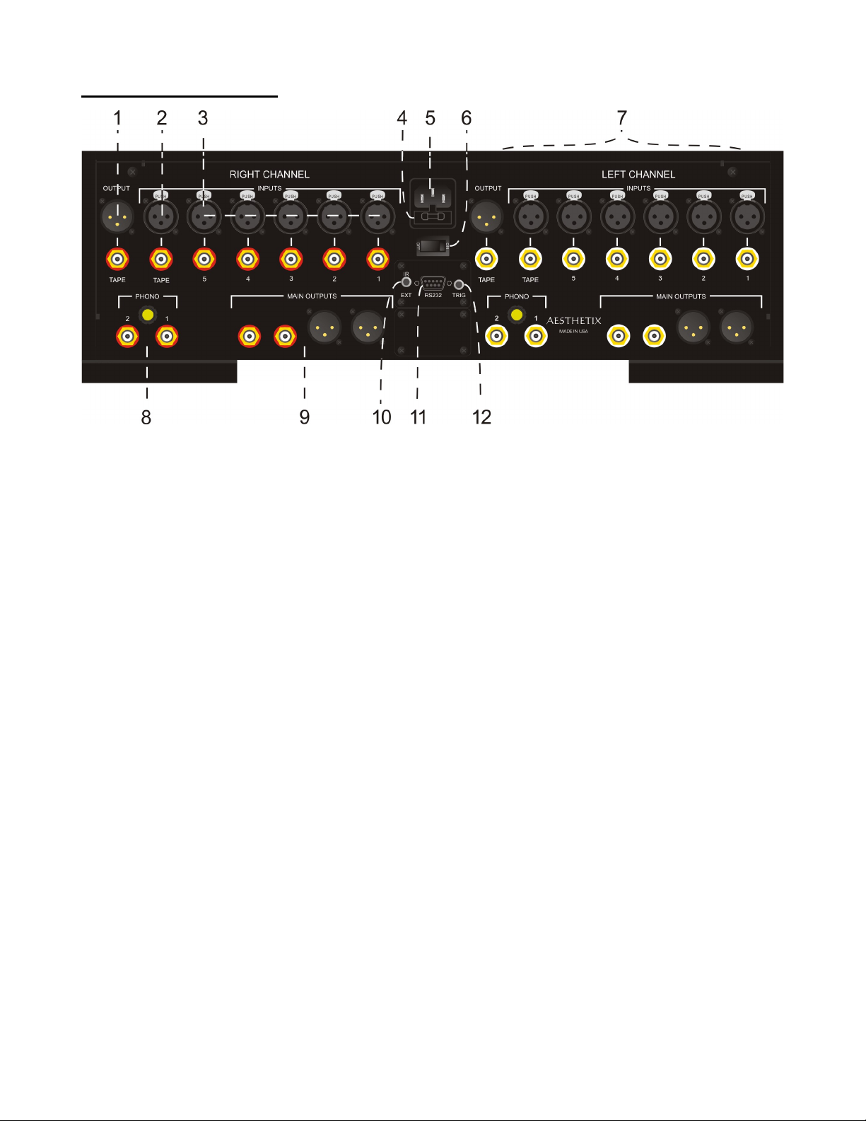
Rear Panel Layout ................................................................................................................ 8
CONNECTIONS ................................................................................................................... 9
AC Power: ......................................................................................................................... 9
Initial Setup .................................................................................................................... 10
Standby ........................................................................................................................... 10
Introduction to the User Interface ....................................................................................... 11
OPERATION .................................................................................................................... 12
Main Menu ....................................................................................................................... 12
Tape In ............................................................................................................................ 12
Phase .............................................................................................................................. 12
Balance ........................................................................................................................... 12
Display ............................................................................................................................. 12
Setup ............................................................................................................................... 12
Setup General .................................................................................................................... 13
Tape Out ......................................................................................................................... 14
Start Level. ...................................................................................................................... 14
Max Level. ....................................................................................................................... 14
Trigger ............................................................................................................................. 14
IR (Infrared) ..................................................................................................................... 15
Set Up Display (Advanced Display Functionality) ............................................................ 15
Restoring the Factory Settings ........................................................................................ 15
Setup Input .................................................................................................................... 16
Input On/Off ..................................................................................................................... 16
Input Level ....................................................................................................................... 16
Home Theater Bypass ..................................................................................................... 17
Input Name ...................................................................................................................... 17
RS232 ............................................................................................................................. 17
Appendix A Troubleshooting Guide ................................................................................ 18
Appendix B Menu Map ................................................................................................... 19
Appendix C RS232 Pinout .............................................................................................. 20
Appendix D Specifications .............................................................................................. 21

7
The Hand Held Remote
The HRC-3 remote is shipped in “Transport” mode, which essentially turns it off. This disables the motion sensor
feature during transportation and preserves battery life.
Please completely read the separate HRC-3 Remote Control Owner’s Manual before using it.
* * *
Metis Front Panel Layout
Figure 1 – Metis Front Panel Layout
1. Left knob. Turn to change the current Input when in the Main Menu. Press to enter sub menus and turn to
change sub menus as outlined in this manual.
2. STANDBY button. After the rear panel Main Power switch is turned on, press the illuminated front panel Standby
button in the center of the logo to exit the standby mode. Pressing this button again will put the
Metis into Standby and illuminate the button LEDs.
3. LED Display. All menus/sub menus are displayed in Appendix B.
4. Right knob. Turn to change the master volume and Press to Mute/un-mute when in the Main menu. It is also
pressed and turned to enter sub menus and edit parameter as outlined in this manual.

8
Rear Panel Layout
Figure 2- Rear Panel Layout
1. Right channel balanced and single-ended Tape Output jacks.
2. Right channel balanced and single-ended Tape Input jacks.
3. Right channel balanced and single-ended Line Input jacks.
4. Main fuse. Replace with same type and rating only. (Spare fuse inside).
5. AC power input connector.
6. Main Power switch. Disconnects AC to all circuits. It is recommended that this be left on at all times during
regular use with the exception of whenever cables are connected/disconnected or when the unit is not going
to be used for an extended period of time.
7. Left channel Input and Output jacks.
8. Right channel Phono input jacks and ground connector. (Optional).
9. Right channel balanced and single-ended Main Output jacks.
10. IR extender input jack. Connect external IR receiver to this input.
11. DB9 RS232 connector. Used for connecting a system control device to the Metis to control and monitor its
functions.
12. Remote Trigger jack. When set to do so, as the Standby button is pressed to take the Metis out of standby,
the rear panel trigger jack becomes active with a 5 VDC signal. A compatible receiving device such as the
Atlas Power amplifier will receive this signal and then change its mode from standby to operate. When the
Standby button is pressed again the signal goes to 0V and puts the receiving device into standby mode. The
Remote Trigger Jack can also be setup as a trigger input, which when receiving a 5VDC signal, takes the
Metis out of standby.

9
CONNECTIONS
CAUTION: Make all input and output connections before turning on the rear panel Main Power switch.
Mute or turn off the power amplifier when connecting/disconnecting cables.
- - - - = Optional Connection
Figure 3 - Rear Panel Layout showing connections
AC Power:
The Metis may be plugged directly into an un-switched wall outlet. Although proprietary RFI (radio-frequency
interference) filtering is built into the Metis, in some situations an AC power-line filter may provide additional
sonic benefits.
* * *

10
Initial Setup
With the AC cord disconnected, remove the Metis top cover by first removing the two Philips
screws on the rear panel closest to the top, then lift each rear corner one at a time – going back
and forth between left and right. It is fastened with a stiff double-sided interlocking material.
Install 4 tubes into the Metis. See Metis Tube Guide. Afterwards, replace the top cover and secure it using the
same 2 Philips screws.
Connect all sources to the Metis rear panel inputs,
If used, connect a trigger cable to the device that the Metis standby will either control, or be controlled by.
Connect the Metis outputs to the Power amplifier inputs.
Ensure that the power amplifiers are off or muted prior to making connections to, and tuning on the Metis rear
panel power switch.
Turn on the rear panel power switch.
Note: The hand held remote is shipped in “Transport” mode (off). It must first be set to Active. Please refer to the
remote owner’s manual. See the Metis Remote Owner’s Manual.
If it’s not already, install one battery in the hand held remote control. Note that a remote extender is included to
extend the remote range, if necessary.
CAUTION! To avoid loud pops and possible speaker damage, turn on all other system components
before taking the Mimas out of standby.
Standby
The Metis will boot up into Standby. Pressing the blue Standby button will initiate the startup process, in which
the blue LED will blink for a few minutes before displaying the Main Menu.

11
Introduction to the User Interface
The Metis can be controlled from either the front panel or the hand held remote. On the front panel each of the 2
knobs can be turned endlessly in either direction, or pressed. Combinations of these actions will give the user
access to all menus and features. The 2 actions of the Left and Right knobs are symbolized as:
The Metis display can be in any one of 4 levels:
1) Main menu. This displays information about the currently selected input, the master volume, if the
Metis is Muted or if the currently selected input is Bypassed.
2) Main menu sub features. Quick access is given to turning the Tape Input jack On or Off, inverting the
Phase, shifting the L/R Balance, viewing/extinguishing the Display LEDs and editing in the General
and Input Setup menus.
3) Setup General. This menu & sub menu accesses all general sub features (non-Input related).
4) Setup Input. This menu accesses all features that are Input specific.
Refer to Appendix B to see all menus & sub menus.
* * *

12
OPERATION
Please refer to Appendix B for a map of all Metis menus.
Note: Put the Metis into Standby before turning off the rear panel AC Power Switch.
Main Menu
When the Metis comes out of standby, it will display the main menu, which consists of the currently selected
input and the master volume level (“BP” if the Input is in bypass mode). If Mute is on, there will be an “M:” to the
left of the volume level.
Turning the Left knob in either direction will change the currently selected input. Tuning the right knob in either
direction will increase/decrease the master volume. Pressing the right knob will Mute/Unmute the Metis. This is
true in most menus/submenus. There are a few cases mentioned later where pressing the Right Knob will be
used to enter a sub menu, after which it will again function as Mute/Un-mute.
Tape In
Pressing the Left knob reveals the first page (Tape IN) of the main menu sub features.
When TAPE IN is displayed, turning the Right knob will turn the rear panel Tape Input jacks On or Off.
Note: When the Tape Input jack is active, the main menu will display TAPE – X, (X is the currently selected
input). This means that the Tape Input is being listening to, but Input X is being routed to the Tape Output. The
Metis can be muted/un-muted by pressing the Right knob.
Phase
Continuing to turn the Left knob clockwise allows the user to set the Phase to 0 or 180 degrees, by turning the
Right knob.
Balance
Turn the Left knob clockwise again will display the Balance feature. Turning the Right knob clockwise or counter
clockwise will shift the balance to the right or left. The range is plus or minus 12. Going past that value turns the
audio off in one channel. The display shows the direction of the shift, followed by the amount. Example: BAL
LT: +2 indicates that the signal is predominantly in the left channel by 2 steps.
Display
Turning the Left knob clockwise allows the Display LEDs to be turned ON or OFF by turning the Right knob.
When the DISPAY is set to OFF turning or pressing any knob will turn the LED’s on for 5 seconds, and then they
will extinguish. The only exception is standby, which will always have the Standby light illuminated.
Setup
The last clockwise turn of the Left knob takes the user to SETUP, where turning the Right knob toggles between
General (GEN) and Input specific Setup menus. Pressing the right knob when one of these Setup menu names
is displayed will enter that sub menu.
* * *
When Mute is enabled / disabled, this change is shown on the display for 3 seconds. After this time the display
will revert to the previous menu.

13
Setup General
The General setup options are:
o Enabling/disabling the rear panel Tape Out jacks.
o Creating a [volume] Start Level when the Metis comes out of standby.
o Setting a maximum level that the Metis can be turned up to (Child proofing & speaker protection).
o Programming the rear panel Trigger to be an Input or an Output.
o Tells the Metis front panel IR receiver to respond to command sets from either the Metis or Calypso
remote control.
o Setting up the front panel display brightness options.
o Restoration of factory presets.
At any time that a sub menu is displayed, unless pressing the Right knob is required to enter a sub menu,
pressing it will Mute/Un-mute the Metis.
There are up to 3 levels of sub menus. When at the first level, pressing the Left knob once will exit and return to
the Main menu. When at a second level, pressing the Left knob once will exit and return to the first sub menu,
once more will reveal the Main menu. Likewise, when at the third level, 3 presses are required to get back to the
Main menu.
* * *

14
Tape Out
The factory default setting is OFF.
To enable or disable the rear panel Tape Out jacks, from the Main menu, press the Left knob and turn it until the
display reads SETUP GEN*. Press the Right knob to enter this sub menu. Turn the Right knob to ON or OFF.
Turning the Left knob will access additional General Setup features or pressing the Left knob once will exit this
sub menu. Press the Left knob once more to return to the main menu.
*If SETUP INx (where x is an Input number) is displayed, turn the Right knob to display GEN.
Start Level.
The factory default is 0 and the programmable range is 0-20.
From the Main menu, to set the volume level that the Metis will be at when coming out of Standby, press the Left
knob and turn it until the display reads SETUP GEN*. Press the Right knob to enter this sub menu. Turn the
Left knob until STARTLVL:XX is displayed, and then turn the right knob to the desired level. Press the Left knob
once to revert to the Setup menu, or twice to return to the Main menu. The change(s) will take affect after the
Metis has been put into Standby.
Max Level.
The factory default is 88 and the programmable range is 50-88.
From the Main menu, to set the maximum level that the Metis will go to, press the Left knob and turn it until the
display reads SETUP GEN*. Press the Right knob to enter this sub menu. Turn the Left knob until
MAXLEVEL:XX is displayed, and then turn the right knob to the desired level. Pressing the Left knob will exit this
sub menu. The change(s) will take affect after the Metis has been put into Standby.
Trigger
The factory default is OUT.
From the Main menu, to set whether the rear panel trigger will be used to send or receive a trigger signal, press
the Left knob and turn it until the display reads SETUP GEN*. Press the Right knob to enter this sub menu.
Turn the Left knob until TRIG: XX is displayed, and then turn the right knob to ON or OFF. Pressing the Left
knob will exit this sub menu.

15
IR (Infrared)
The factory default is Metis.
From the Main menu, to set whether the Metis responds to a default Metis or Calypso remote, press the Left
knob and turn it until the display reads SETUP GEN*. Press the Right knob to enter this sub menu. Turn the
Left knob until IR: XX is displayed, and then turn the right knob to METIS or CALYPSO. Pressing the Left knob
will exit this sub menu.
Set Up Display (Advanced Display Functionality)
Note: If edited via the front panel, the user’s hand or body could shadow the path of the ambient room light level
that the Metis light sensor reads. Therefore it is recommended to view/edit this feature via the hand held
remote.
The Metis is able to sense the ambient light level in the room and adjust its LED brightness accordingly. While
the factory settings will work for most situations, there may be times when adjustment to the settings is useful.
Should it be desired to edit these settings, from the main menu, press the Left knob and turn it until the display
reads SETUP GEN*. Press the Right knob to enter this sub menu. Turn the Left knob until SETUP DISP is
shown, and then press the Right knob to enter this sub menu.
The display will read RM:YY LED:ZZ. YY = the room brightness and ZZ = the LED brightness for that room light
level. Each has a range between 0 and 15, where 0 is the darkest and 15 the brightest.
To make adjustments, turn the Left knob to the desired ambient room light level setting and then turn the Right
knob to adjust the LED brightness for that room light level. Pressing the Left knob once will revert to the
Display Setup menu, twice to get to the General Setup menu, and once more to get to the Main menu.
Note: Setting all brightness levels to the same value, for all light levels, will result in no change of LED brightness
with changes in ambient light level in the room.
Restoring the Factory Settings
From the Main menu, to restore the Metis factory settings, press the Left knob and turn it until the display reads
SETUP GEN*. Press the Right knob to select this sub menu. Turn the Left knob until RESTORE: is displayed.
Turn the right knob to YES (or NO to abort). At YES, press the Right knob. Pressing the Left knob will exit this
sub menu.

16
Setup Input
The Input setup options are:
o Enabling/Disabling the currently selected Input.
o Adjusting the input level to match that of other inputs.
o Selecting the Input to be used for Home Theater Bypass.
o Naming the Input.
At any time that a sub menu is displayed, unless pressing the Right knob is required to enter a sub menu,
pressing it till Mute/Un-mute the Metis.
* * *
Input On/Off
The factory default is ON.
From the Main menu, to set whether an Input is active or not, press the Left knob and turn it until the display
reads SETUP INx*. Turn the Right knob to select InX, where X is the input number to be edited. Press the Right
knob to enter this sub menu and then turn the right knob to ON or OFF. Pressing the Left knob will exit this sub
menu.
**If SETUP GEN is displayed, turn the Right knob to display INPx.
Input Level
The factory default is 0.
Sources may have different output levels. To streamline this, the Metis allows the user to adjust any Input level
to match that of other sources. The range is –12 to + 12.
From the Main menu, to change the level an Input, press the Left knob and turn it until the display reads SETUP
INx**. Turn the Right knob to select INX. Where X is the input number to be edited. Press the Right knob to
enter this sub menu. Turn the Left knob to select xLEVEL, and then turn the right knob in either direction to set
the desired offset. Pressing the Left knob will exit this sub menu.

17
Home Theater Bypass
The factory default is OFF. On the Main menu, a Bypassed input will be displayed as Inputx BP. On a Bypassed
Input, volume and mute changes are disabled as the source device will control these features.
From the Main menu, to enable or disable Bypass for an Input, press the Left knob and turn it until the display
reads SETUP INx**. Turn the Right knob to select INx. Press the Right knob to enter this sub menu. Turn the
Left knob to select Bypass. XBYPASS:YY will be displayed, where X = the Input number and YY = ON or OFF.
Turn the right knob to ON or OFF. Pressing the Left knob will exit this sub menu.
Input Name
Each input can be named using up to six characters. The available characters are A-Z, ., ., 0-9, :, ;, <, =, > ?
and @.
To name an Input, from the Main menu press the Left knob and turn it until the display reads SETUP INx**. Turn
the Right knob to select Inx, where x = the input number to rename. Press the Right knob to enter this sub menu
then Turn the Left knob to display INPUTxNAME. Press the Right knob enter the Naming sub menu. Turn the
Left knob to the desired character to edit. This character position will be underlined. Turn the Right knob to
select the desired character. To edit another character position, Turn the Left knob to select the desired
position, then Turn the Right knob to edit the character. Continue in this method until the Input is named as
desired. Press the Left knob to exit this sub menu.
etc
RS232
All functions of the Metis can be controlled and monitored via RS232, using the DB9 connector. As long as the
rear panel power switch in turned on, the RS232 circuitry is always active, thus allowing the Metis to be taken out
of STANDBY via RS232. Refer to Appendix C for more information on using RS232.
Please contact Aesthetix for RS232 and Remote IR commands.

18
Appendix A Troubleshooting Guide
If the Metis should function abnormally during operation, please review the items in the following checklist. Please
be sure to thoroughly check all other connected components such as speakers, preamplifiers, as well as cables.
Symptom Possible Cause(s) Remedy
No power or front panel
lights and no sound.
Power cable is not inserted 100% into AC
input connector.
Ensure that the AC cord is inserted all the
way into the Metis and that the wall outlet is
active with the appropriate voltage.
Power Supply fuse(s) is (are) open. Replace with same type and rating ONLY.
Rear panel fuse is open. Replace with same type and rating ONLY.
Circuit breaker is open (AC outlet). Check the AC outlet circuit breaker and reset,
if necessary, or contact your dealer.
No audio output. Incorrect source is selected. Look in the display to verify that the correct
source is shown. If it is not, press the Input
button repeatedly until it is.
Mute is active. Un-mute the Metis.
Current Input is set to Bypass. If the right side of the display indicated BP
verify that the source is outputting a signal.
Remote flashes 5 times
with each button press.
Low battery. Replace the battery in the HRC-3 remote.
Hot/Warm. Normal operation.

19
Appendix B Menu Map

20
Appendix C RS232 Pinout
Figure 4 – Metis RS232 Jack Pinout
These are the connector drawings only. The RS232 cable must be a regular RS232 or mouse extender cable,
wired pin for pin.
The RS232 Protocol data is available upon request.
Table of contents
Other Aesthetix Amplifier manuals