AETA 4MinX User manual
AETA AUDI O SYSTEM S
18-22, avenue Edouard Herriot ±Kepler 4 ±92350 Le Plessis Robinson ±FRANCE
Tél. +33 1 41 36 12 00 ±Fax +33 1 41 36 12 69 ±Web: http://www.aeta-audio.com
55 000 061 - H
4MinX - User manual
Specifications subject to change ±All rights reserved by AAS September 13 55000061H_4MinX_en.docx
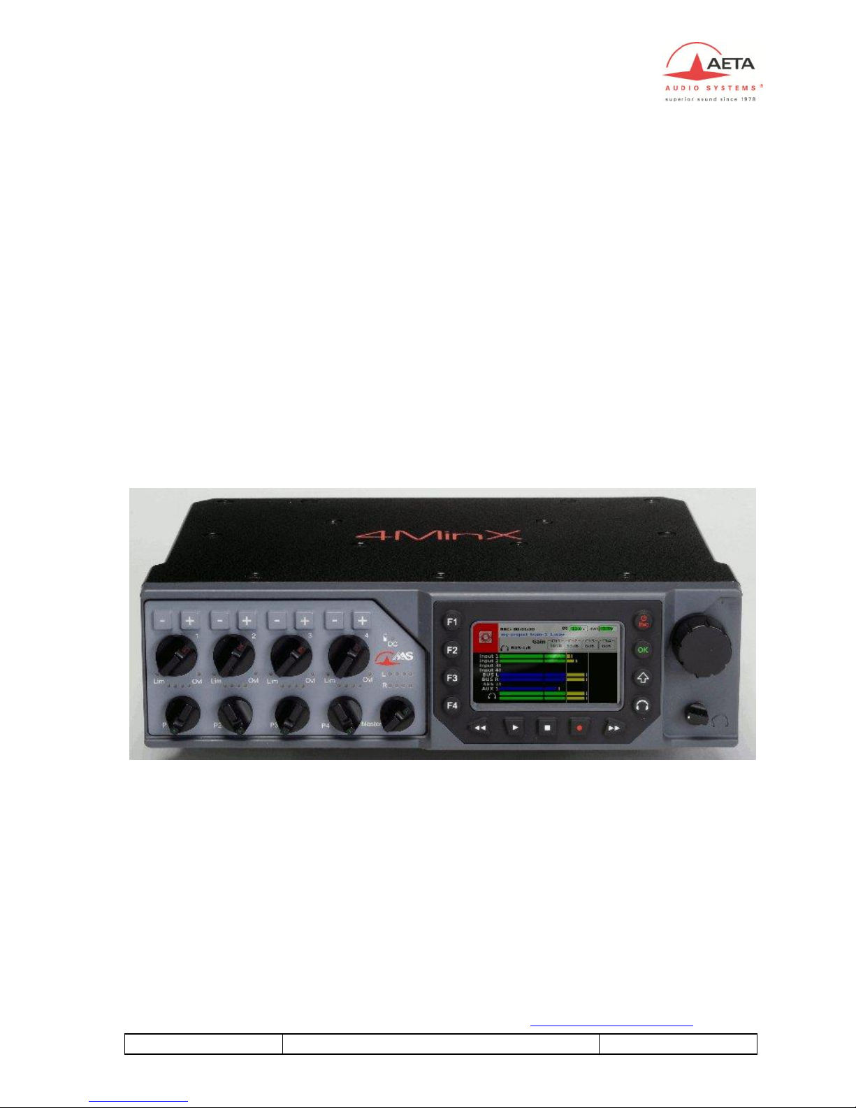
4MinX&
Portable M ixer/Recorder
User manual


55 000 061 - H
4MinX - User manual
Index
1.!Technical Characteristic...........................................................2!
2.!AUDIO Interfaces......................................................................3!
2.1. Audio Inputs .................................................................................................3!
2.1.1. ,QSXW³0LF/LQH´ ...................................................................................3!
2.1.2. Line inputs/return ..................................................................................6!
2.1.3. (PEDVH³(;7,2´5pFHSWHXUV+) ......................................................6!
2.1.4. AES Inputs ............................................................................................7!
2.2. Audio outputs ...............................................................................................7!
2.2.1. 0DLQRXWSXWV³/LQH2XW´ .......................................................................7!
2.2.2. 8QEDODQFHG³/LQH2XW´ .........................................................................7!
2.2.3. Analog outputs for radio transmitters ....................................................7!
2.2.4. Digital outputs .......................................................................................8!
2.3. Monitor .........................................................................................................8!
2.3.1. Display screen .......................................................................................8!
2.3.2. Configuration ........................................................................................9!
2.3.3. Headphone monitoring ........................................................................11!
2.4. Internal alignment signal generator ............................................................11!
2.5. Intercom / Slate microphone.......................................................................12!
3.!Powering...................................................................................13!
3.1. Specifications.............................................................................................. 13!
3.1. Switching on and off...................................................................................14!
4.!Menu description.....................................................................15!
4.1. General principles.......................................................................................15!
4.2. Menu structure ............................................................................................16!
4.3. Menu : « Audio »........................................................................................ 18!
4.3.1. Menu : « Audio Inputs »......................................................................18!
4.3.2. Menu : « Audio Output » ...................................................................19!
4.3.3. Menu : « Coupling »............................................................................19!
4.3.4. Menu: « Routing »...............................................................................19!
4.3.5. Menu : « P1-P4 function »...................................................................20!
4.3.6. MIDI Menu .........................................................................................21!
4.3.1. Menu « Master gain»..........................................................................23!
4.3.2. Menu « Mixdown Limiter» .................................................................23!
4.4. Menu : « Recording » .................................................................................23!

4MinX - User manual
55 000 061 - H
4.4.1. Menu: « Project Management » ......................................................... 23!
4.4.2. Menu : « File Management ................................................................. 26!
4.4.3. Menu : « Filename template »............................................................. 29!
4.4.4. Menu : « Meta data » .......................................................................... 29!
4.4.5. Menu : « File format » ........................................................................ 32!
4.4.6. Menu : « Pre-record » ......................................................................... 32!
4.4.7. Menu : « Backup False take »............................................................. 33!
4.4.8. Menu « Backup to USB » ................................................................... 33!
4.5. Menu « Settings »....................................................................................... 34!
4.5.1. Menu : « Synchronization »................................................................ 34!
4.5.2. Menu : Time Code ( Option).............................................................. 35!
4.5.1. Menu : « Snapshots ».......................................................................... 36!
4.5.2. Menu : « Tone ».................................................................................. 36!
4.5.3. Menu : « Display ».............................................................................. 36!
4.5.4. Menu : Function keys.......................................................................... 36!
4.6. Menu : « Tools » ........................................................................................ 37!
4.6.1. Menu : Power down ........................................................................... 37!
4.6.2. Menu : Sleep ...................................................................................... 37!
4.6.3. Menu : Eject media ............................................................................ 37!
4.6.4. Menu : Reset settings ......................................................................... 38!
4.6.5. Menu : Import/export configurations ................................................. 38!
4.6.1. Menu : Format media......................................................................... 38!
4.6.2. Warning .............................................................................................. 39!
4.6.3. Update................................................................................................. 39!
5.!Operating mode ±Detailed description.................................40!
5.1. Interface ..................................................................................................... 40!
5.2. Start a record .............................................................................................. 41!
5.3. Play a take .................................................................................................. 42!
5.3.1. Navigation........................................................................................... 42!
5.3.2. Play ..................................................................................................... 42!
5.3.3. Monitoring .......................................................................................... 42!
5.3.4. Search or modify a take ...................................................................... 43!
5.4. Shortcuts..................................................................................................... 44!
5.1. Quick Screens/configurations..................................................................... 44!
5.1.1. Inputs configuration ............................................................................ 45!
5.1.2. Audio Routing..................................................................................... 46!
5.2. Snapshots ................................................................................................... 47!
5.2.1. Save / Load ......................................................................................... 47!
5.2.2. Export ................................................................................................. 48!

55 000 061 - H
4MinX - User manual
5.2.3. Import..................................................................................................48!
6.!Audio couplings.......................................................................50!
6.1. Microphones ...............................................................................................50!
6.1.1. Monophonic ........................................................................................50!
6.1.2. Stereophonic........................................................................................51!
6.1.3. Surround ..............................................................................................52!
6.2. Stereo coupling ...........................................................................................54!
6.3. M/S coupling ..............................................................................................55!
6.4. Double M/S coupling..................................................................................56!
6.5. Link all 1 to 4..............................................................................................58!
6.6. Soundfield A/B format (Optional) ..............................................................59!
7.!Technical Specifications..........................................................63!
7.1. Microphone/Line inputs..............................................................................63!
7.2. Line input....................................................................................................64!
7.3. AES inputs..................................................................................................64!
7.4. "Line Out" balanced analog outputs ...........................................................65!
7.5. "Line Out" unbalanced analog outputs ....................................................... 66!
7.6. Digial outputs ............................................................................................. 66!
7.7. Headphone output.......................................................................................67!
7.8. "Direct I/O" interface..................................................................................67!
7.9. "EXT I/O": Interface for RF transmitters/receivers ....................................68!
7.10. Power supply ............................................................................................69!
7.1. Time Code ..................................................................................................69!
7.2. Dimensions and weight...............................................................................70!
7.3. Environmental ............................................................................................ 70!
7.4. Options Hirose 10Pins ................................................................................71!
8.!Annexes.....................................................................................72!
8.1. iXML ..........................................................................................................72!
8.2. Overview of connectors and front panel elements ......................................74!
8.3. Block diagram.............................................................................................77!
8.4. Level maps..................................................................................................79!
8.5. Filters..........................................................................................................80!
8.6. Limiter ........................................................................................................81!

4MinX - User manual
55 000 061 - H
8.7. Accessories................................................................................................. 82!
9.!Notes.........................................................................................86!
Revision:
H ±Build on firmware V1.7.3

55 000 061 ±H
4MinX - User manual
1
Introduction
4MINX is a portable mixer specially designed for outside recording.
4Minx is new kind of product on this market. It can be use as a traditional
mixer, but can be use as a multi tracks recorder. In same time, it can manage
digital audio treatment in real time.
This equipment is suitable for sound production, with its remarkable audio
features and its full compatibility with « M/S » and « surround » systems.
4Minx have 4 Mic/Line inputs, with all power phantom and limitor, 2 digital
inputs AES3. Digital inputs support the normalization AES42 for digital
microphones (10v phantom power).
4Minx has many outputs, 6 analog channels and 6 digital channels AES3.
The routing capability for each input and each output give complete liberty to
the user.
The multi tracks recorder can grow up to 8 tracks on SD/SDHC card and can
make a backup on external USB disk. You should use SD/SDHC card Class 10
or similar to avoid problems.
A project management included in the unit gives the opportunity to make many
sounds recording without problem.
4MinX has a keyboard and a ´TFT high quality display, offer a simple and
nice user interface. On 4Minx the user can set its own mixer interface in regards
inputs and outputs need in his configuration.
To start a work quickly, you can read the quick start delivery with the unit. It
will provide you all details step by step to start a record.

2
4MinX - User manual
55 000 061 - H
1. Technical Characteristic
xLight weight and small dimensions (1.9 kg, 260 x 75 x 195 mm)
x4 Mic/Line transformerless inputs, very low noise (-128dBu)
xAdjustable input gain, 10 dB steps, 0 to +50 dB
xHigh-pass filters on each channel
xMaximum overall gain: 90 dB, useful for dynamic and ribbon
microphones
xMaximum input level: +19 dBu without pad
xInput headroom: 40 dB, independent of input stage gain
xLED for overload warning on each input channel
xFast limiter on each input, 40 dB operating range, with LED indicator
xStereo or M/S coupling on inputs 1&2 et 3&4
xStereo lM/S encoder/decoder on inputs 1 & 2, 3 & 4
x4 main line outputs, maximum level adjustable from -9dBu to +22dBu
x2 return or auxiliary line inputs, maximum acceptable level adjustable
from -9dBu to +22dBu ( for 0dBFS)
xseparate Stereo lM/S encoders/decoders, for monitoring
x2 unbalanced outputs (level 6 dB below the balanced outputs)
x´49*$7)7VFUHHQZLWKDGMXVWDEOHEULJKWQHVVGLVSOD\LQJlarge
scale bargraphs (50 dB dynamic range)
xHigh performance headphone amplifier, with selectable source and
listening mode
xLong operating range on Li-Ion DV battery and charger inside
x3 AES3 digital outputs, stereo, 24 bits, up to 96 kHz
x2 AES3 digital inputs with phantom +10V for AES42 microphones
with sample rate convertor.

55 000 061 ±H
4MinX - User manual
3
2. AUDIO Interfaces
The functions of the analog and digital mixer are shown on the functional
diagram that can be found in annex,³Block diagram´2QQH[WSDUDJUDSKZH
will describe in detail all inputs and outputs of the 4MinX
2.1. Audio Inputs
2.1.1. ,QSXW³0LF/LQH´
Each of these four inputs is available on a 3-pin female XLR socket, and
is electronically balanced. Each input support 48V phantom power or T12
power. If no powering is active, unbalancing an input has no negative impact on
the performance.
. Each input has its own volume control on the front panel, generally
named « fader ».
Specificities:
-,QSXWVDQGFDQDOVREHIHGIURPWKH³(;7,2´VRFNHWLQZKLFK
case no microphone powering is available
-Input 1 and 2 can stand very strong audio levels thanks to a 20 dB
attenuator. When it is enable, the input level can grow up to +39dBu.
)XQFWLRQVRIWKH³0,&/LQH´LQSXWV
The following functions are available on each input, via a selection in the menu:

4
4MinX - User manual
55 000 061 - H
xInput stage gain setting, 0dB to +50dB, 10dB steps;
x3KDQWRPSRZHUIRUDPLFURSKRQH9RU³7RQDGHU9´ ;
xAnalog high-pass filtering, 50 Hz cut-off frequency, 18dB/octave;
xDigital high-pas filtering, 50 Hz to 200Hz 12dB/octave and 300 Hz,
6dB/octave, suitable for compensating proximity effects in directional
microphones
xPolarity inversion (phase reversal)
x)DVWOLPLWLQJZLWK³VRIWNQHH´
xRouting to Left or Right bus, or Center (i.e. L and R), with pan-pot, or
not routed at all
x7KH³ULVNRIRYHUORDG´/('EHJLQVWROLJKWDW dB below overhead.
xAttenuator ( 20dB ) can be enable on the mic/line input 1 & 2
Note:
-The 50Hz analog filter can be enabling in the same time as the digital
filtering. In this case rate will be 32dB/Oct below 50Hz.
-A limiter can be inserted into each channel (post-fader). Its activation
is shown by a green LED that turns red when the signal begins to limit.
Stereo and M/S
Via menu selection, channels 1 and 2, 3 and 4 can be used as
independent channels or coupled for stereo or M/S operation. When used as a
couple of stereo or M/S channels, the channel impair becomes the master,
controlling the level of both channels. The channel pair provides +/-5dB
adjustment of the balance in L/R mode (normal stereo), or the stereo width in
M/S mode.
In normal stereo mode, the transducers usually have matching sensitivity:
xAny change of the input gain on one channel induces the same on
the other channel;
xThe even channel control controls the balance between L and R
channels by +/- 6dB

55 000 061 ±H
4MinX - User manual
5
xInput odd is routed to the Left bus, input pair is routed to the
Right bus
xThe even input is routed on the mix down Left and the odd on
the mix down right. But, Over writing these routing remains
possible!
,Q³06´PRGH the transducers often have different sensitivity:
xThe input gain adjustment is kept separate for channels odd and
even,
xThe odd channel control adjust the couple level
xThe event channel control adjusts the stereo image width. In the
center detent position, a coherent couple should provide a
normalized 110° angle
xWhenever inverting the phase of channel even, after decoding
from M/S to L/R the stereo image is reserved LlR
xManual routing is inhibited and the signals are routed and
decoded as follows:
,QSXWLPSDLULVWKH³0´VLJQDOLQSXWSDLULVWKH³6´VLJQDO
Input impair + Input pair (M+S) is routed to the Left bus;
Input impair - Input pair (M-S) is routed to the Right bus.
Limiters
A limiter can be inserted into each channel, after the channel fader. This is a
fast limiter with a dynamic range wide enough to stand the 40 dB overhead of
the input stage. The activation of the limiter is shown by an LED.
As long as the signal level stays below the limiter threshold, little effect is seen
on the signal. When the limiter is triggered, its output stays 6dBFS below the
A/D converter clipping level for up to 40dB input overdrive.
,WFDQWKXVEHVHHQDVD³VDIHW\´OLPLWHUWKDWPD\EHOHIWDFWLYHDOOWKHWLPH
The threshold can be adjusted through the menu from ±12dBFS to ±3dBFS

6
4MinX - User manual
55 000 061 - H
Note: In case of use specific coupling the limiters are coupling together, which
is the required mode for applying simultaneous and identical gain reduction to
both channels in « stereo » and M/S modes, in order to preserve the coherence
of the stereo image.
2.1.2. Line inputs/return
Two inputs are available on a 5-pin female XLR socket, and are electronically
balanced. It is possible to unbalance an input without negative impact on the
performance. Each channel has its own maximum level adjustment in the menu
from -9dBu to +22dBu (for 0dBFS). Theses inputs can be use as a return from
video camera but can be use as more analog entries for the mix down or the
recorder. It is possible to have a fader control on each input through P1 to P4. In
this case, we provide you 15dB more gain.
2.1.3. (PEDVH³(;7,2´5pFHSWHXUV+)
7KH³(;7,2´VRFNHWLVDYDLODEOHIRUWKHFRQQHFWLRQRIDQRSWLRQDO
extension box. This device can be used to interface 4MINX with radio
transmitters and/or receivers.
:KHQWKHH[WHQVLRQGHYLFHLVSOXJJHGLQWRWKH³(;7,2´VRFNHWWKH
mixer can use, for channels 3 and/or 4, inputs from the EXT I/O socket instead
of XLR inputs 3 and 4. In this case NO microphone power is apply on these
inputs.
The extension device feeds these inputs with two balanced signals. For
safety, no microphone powering is inserted into these inputs on the EXT I/O
socket but all others settings are the same.
On this interface, you have 2 asymmetrical outputs. Theses outputs are
described on the need paragraph.
Note: A 9V/ 600mA power supply is available on the connector.

55 000 061 ±H
4MinX - User manual
7
2.1.4. AES Inputs
4MINX can accept AES3 digital audio input on its « Dig. In » (XLR 3 pins).
Signals can be routed or mixed in the bus as others inputs or send to any
outputs.
The input 1&2 can be used to synchronize the 4minx on another machine. This
feature can be set in the synchronization menu, it is necessary to specified in the
same menu the frequency of the AES signal. Both digital inputs are using a
sample rate convertor when you are in master mode.
Note: Don't forget to set the right sample frequency on the synchronization
menu when you want to use the AES input as synchronization
2.2. Audio outputs
2.2.1. 0DLQRXWSXWV³/LQH2XW´
4Minx have 2 stereo line outputs on XLR 5 pins. By menu, you can set
source for each channels between all inputs, bus, monitoring.
The signals are electronically balanced; they can be unbalanced with no
impact on performance, as long as the level stays below +19dBu.
The maximum output level (which corresponds to the maximum digital
level, 0dBFS) is adjustable via the menu, from -9dBu to +22dBu.
Also via the menu, a 40dB attenuator can be inserted on each output
FKDQQHOVRSURYLGLQJD³PLFURSKRQHOHYHO´VLJQDO.
2.2.2. 8QEDODQFHG³/LQH2XW´
7KHVDPHVLJQDOVRIWKHILUVW³VWHUHR´OLQHRXWSXWDVIRXQGRQWKH;/50
socket are also fed to a 3.5mm stereo mini-jack socket. These signals are
unbalanced, and their level is 6dB below those on the balanced XLR5M .Their
typical use is for linking the mixer to a semi-professional recorder (Mini-Disc,
FDVVHWWH'$7«RUFRQQHFWLQJDVHFRQGKHDGSKRQH
2.2.3. Analog outputs for radio transmitters
8
4MinX - User manual
55 000 061 - H
The L and R mix buses or any inputs can output on the « EXT I/O »
socket (on the left side of the unit), with a separate adjustment of the maximum
level for each channel from -20dBu to +10dBu, which allows a suitable
adaptation to most radio transmitters. These outputs are asymmetrical.
2.2.4. Digital outputs
4MINX delivers 24-bit stereo digital outputs; it is possible (via the menu) to
VHOHFWHLWKHUD³3UR´PRGHRU³&RQVXPHU´PRGHGHSHQGLQJRQWKHW\SHRI
equipment the signals are fed to.
A balanced and transformer isolated AES output (110Ohm impedance) is
DYDLODEOHRQWKH³'LJ 2XW´VRFNHW It is possible to connect this AES output to a
SPDIF input through an adaptor cable (optional: see Annex).
2.3. Monitor
2.3.1. Display screen
7KHGLVSOD\VFUHHQRI0,1;LVD´Folor QVGA TFT display. This
technology features a very wide viewing angle and fast response time. The
display brightness is adjustable, it has latest technology for a perfect outside
used.
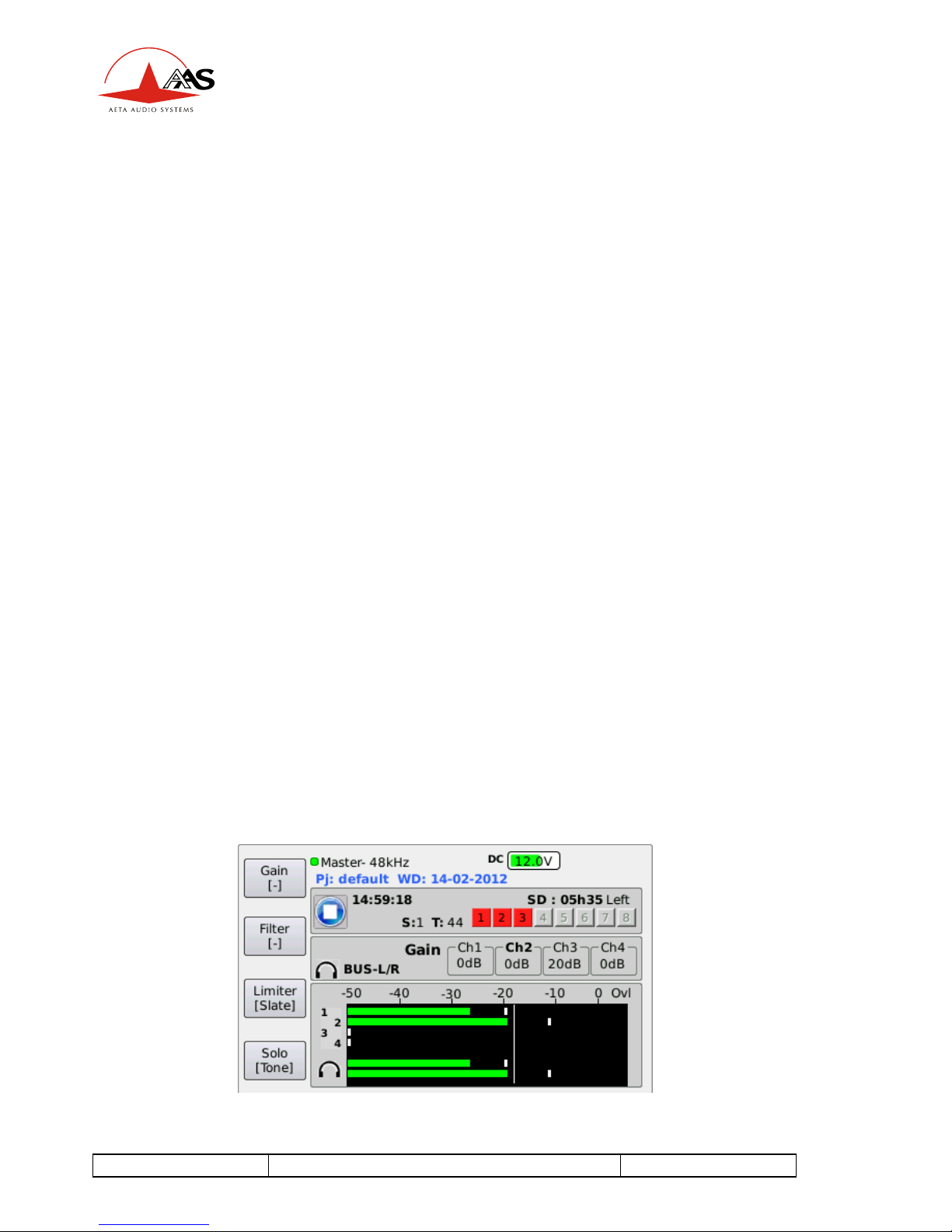
On the main screen:
-The monitoring audio level of left and right signals are showing at the
bottom of the display
-Just over them the level of the four mixer channels is shown.
55 000 061 ±H
4MinX - User manual
9
-Levels are displayed on large scale bargraphs covering -50dBFS to
0dBFS.
-By menu you can set 4 metering level threshold (Minimum, nominal,
yellow, red)
-They are measured with fast PPM ballistics.
-In addition, peaks are held on for about 4 VHFRQG³SHDN-KROG´
function)
-$Q³29/´LFRQVKRZVXSZKHQHYHUWKHOHYHOUHDFKHV-3dBFS or more.
-Input number are display in red when you enable a coupling between
us (when 2 stereo or M/S coupling are selected, the second is show in
blue).
-,I\RXVHOHFWSUHIDGHUE\PHQXIRUWKHLQSXWDµP¶is display
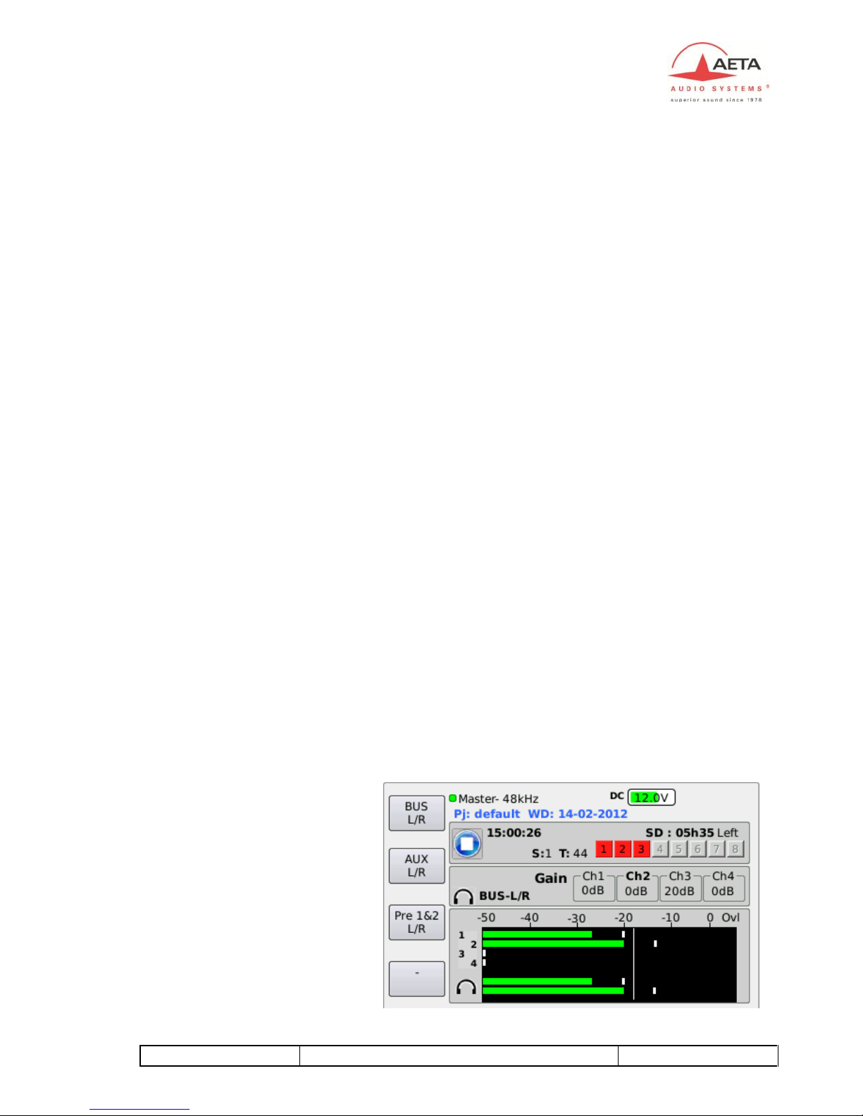
2.3.2. Configuration
The « Monitor » function allows the selection of signals inside 4MINX for
displaying their levels on the screen and monitoring them on headphones
Just by pressing monitor key and moving the rotary, you can select the
following signal sources for monitoring:
xInput 1 to 4, in post or in prefader
xChannel couple : AES 1&2, AES 3&4
xReturn/Line In couple of signals
xBus
x«
Note: The selection can
be affected on one of
function key ( F1 to F4)
by a presson it.
A second bank is
available by pressing the
Shift
You have a total of 8
monitoring presets
10
4MinX - User manual
55 000 061 - H
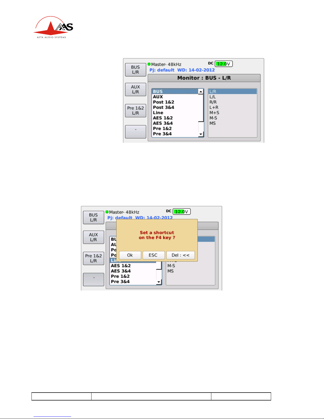
Note: When presets are
available, you should
presstwice the
monitoring key to access
to this menu.
Note: pressthe monitoring key to swap between sourcesand mode.
To set a shortcut key, you have just to pressit under thisdisplay. The current
selected source and mode will be saving on thisshortcut key.
Example: Set preset F 1

55 000 061 ±H
4MinX - User manual
11
2.3.3. Headphone monitoring
The headphone can be plugged into a stereo 6,35mm jack socket. By pressing
twice the monitoring key and vertically moving the cursor with the rotary, the
monitor mode can be selected among the following:
xL/R : Normal stereo listening ;
xL/L: left signal on both ears ;
xR/R: right signal on both ears ;
xL+R : mono sum (L+R) on both ears;
(useful for mono compatibility and phase coherence checking)
xM+S : M+S sum (normally left signal) on both ears ;
xM-S : M-S sum (normally right signal) on both ears ;
xM/S: listening of encoded signals (sum and difference)
The L/RlM/S matrixing is used for example to listen a conventional stereo
signal (L/R) when monitoring M/S microphones, or when monitoring outputs
that have been M/S encoded.
xAlternatively, when the mixer is operated in normal stereo mode,
encoding the signals for monitoring can be used to check the stereo
correlation, by comparing the relative amplitude of the M and S signals
2.4. Internal alignment signal generator
An integrated double oscillator can deliver a sinusoidal 1 kHz on the left and a
400Hz on the right to outputs. This can be used to align analog equipment
connected to these outputs. This signal is activated on all outputs (analog and
digital).
The peak level of the generator is -18dBFS (EBU digital reference level) by
default but can be adjusted by menu from (-20dBFs to 0dBFS).
A function key can be set to have a direct access to the

12
4MinX - User manual
55 000 061 - H
2.5. Intercom / Slate microphone
$PLFURSKRQHLVLQWHJUDWHGLQ0,1;¶VIURQWSDQHOLWVDPSOLILHGVLJQDOFDQEH
inserted into the analog/digital outputs (replacing the normal audio signals). See
audio routing, Slate.
A function key can be set to have a direct access to the feature.

55 000 061 ±H
4MinX - User manual
13
3. Powering
3.1. Specifications
4MINX operates from Li-Ion DV battery type NPF-9x0. The integrated charger
can recharge it from an external DC supply in less than 7 hours (depending of
the battery capability).
The DC/Bat LED becomes red to show the proper operation of the internal
charger. This LED becomes green at the end of the charge. If you don't want to
charge the battery, you should use a dedicated power cable without connection
on the Charger dc input pin (See connectors paragraphs), which may be
desirable e.g. if the external source is itself derived from a battery pack.
4MINX can operate from an external source of 8 V to18 V DC voltage.
4MINX draws constant power from the external source when the voltage
changes. 10V minimum is need for charging.
The same LED becomes green to indicate the presence of the external
power source. 4MINX switches automatically between its internal battery and
the external source, without any noise (priority is given to the external source
when it is available!)
The low battery level can be adjusted by menu from 6,9v to 7,3v. When this
threshold isreached, a warning message isdisplay on the screen and the
battery icon isset in red.
Whenever the battery voltage goesdown to 6.9 V, 4M INX isautomatically
shut of f . This prevents damaging the battery by discharging it too deeply.
0,1;¶VSRZHUFRQVXPStion and hence its battery range depend much on the
operating conditions, such as the number and powering mode of the
microphones, headphone impedance and listening level, etc.
However, as an example, starting with a full charged battery, 4MINX will
operate for at least 7 hours (Sony NP-F970) with dynamic microphones
(including ribbon microphones) and a 600 :headphone. In such condition,
4MINX draws less than 500mA from a 14.4V external source.
4MINX draws a near-constant power (not a constant current) from the external
source when the voltage varies

14
4MinX - User manual
55 000 061 - H
3.1. Switching on and off
+ROGGRZQWKH³(VF´EXWWRQIRUPRUHWKDQVHFRQGVWKHVFUHHQZLOOOLJKWXS
and display the AAS logo after few seconds and after the application start.
To switch off the unit, you can go in the menu tools and select power
down2U\RXFDQSUHVV³(VF´GXULQJVDQGSUHVV)WRFRQILUPLike that, you
will preserve the integrity of the systems and limits the risks to have defective
audio files.
Note: It is possible to switch off the unit E\KROGLQJGRZQWKH³(VF´EXWWRQIRU
more than 10 seconds. This should be use only for emergy used.
Table of contents
Other AETA Music Mixer manuals


