Afterglow FW-CTGSQFP User manual

Cottage 34 in Square Gas Fire Pit
ITM./ART.#: 25XY92001
MODEL#: FW-CTGSQFP
S
E
D
G
N
R
E
C
T
I
F
I
I
E
D
R
ANSI Z21.97/CSA 2.41-2014
Outdoor Decorative Gas Appliances
Installer: Leave these instructions with consumer.
Consumer: Keep these instructions for further reference. WARNING: For Outdoor Use Only.
DANGER
If you smell gas:
Shut off gas to the appliance.
Extinguish any open flame.
If odor continues, keep away from the
appliance and immediately call your
gas supplier or fire department.
WARNING
Do not store or use gasoline, or other
flammable vapors and liquids,in the
vicinity of this or any other appliance.
An LP-cylinder not connected for use
shall not be stored in the vicinity of
this or any other appliance.
DANGER CARBON MONOXIDE HAZARD
This appliance can produce carbon monoxide which has
no odor.
Never use this appliance in an enclosed space such as a
camper, tent, car or home.
Using it in an enclosed space can kill you.
Questions, Problems, Missing Parts?
Before returning to your retailer, email us at
Improper installation, adjustment, alteration, service
or maintenance can cause injury or property damage.
WARNING:
Read the installation, operating, and maintenance
instructions thoroughly before installing or servicing
this equipment.
01

02
DANGER FLAMMABLE GAS UNDER PRESSURE.
LEAKING LP-GAS MAY CAUSE A FIRE OR EXPLOSION IF IGNITED
CAUSING SERIOUS BODILY INJURY OR DEATH.
CONTACT LP GAS SUPPLIER FOR REPAIRS, OR DISPOSAL OF THIS
CYLINDER OR UNUSED LP-GAS.
WARNING FOR OUTDOOR USE ONLY.*
DO NOT USE OR STORE CYLINDER IN A BUILDING,
GARAGE OR ENCLOSED AREA.
Know the odor of LP-gas. If you hear,
see or smell leaking LP-gas, immediately
get everyone away from the cylinder and
call the Fire Department. Do not attempt
repairs.
Caution your LP-gas supplier to:
Be certain cylinder is purged of trapped
air prior to first filling.
Be certain not to over fill the cylinder,
Be certain cylinder requalification date is
checked.
LP-gas is heavier than air and may settle in
low places while dissipating.
Contact with the liquid contents of cylinder
will cause freeze burns to the skin.
Do not allow children to tamper or play with
cylinder.
When not connected for use, keep cylinder
valve turned off. Self contained appliances
shall be limited to a cylinder of 30 lb capacity
or less.
Do not use, store or transport cylinder where it
would be exposed to high temperatures. Relief
valve may open allowing a large amount of
flammable gas to escape.
When transporting, keep cylinder secured in an
upright position with cylinder valve turned off.
WARNING:
DANGER: Do not store a spare LP cylinder under or near barbecue grill, or other heat sources.
NEVER fill an LP cylinder beyond 80% full: a fire causing death or serious injury may occur.
Use only in compliance with applicable codes.
Read and follow manufacturer’s instructions.
Consult manufacturer’s instructions concerning the
cylinder connection provided with your appliance.
Be sure regulator vent is not pointing up.
Turn off all valves no the appliance.
Do not check for gas leaks with a match or open
flame. Apply soapy water at areas marked “x”.
Open cylinder valve. If bubble appears, close
valve and have LP-gas service person make
needed repairs. Also, check appliance valves and
connections to make sure they do not leak before
lighting appliance.
Light appliance(s) following manufacturer’s
instructions.
When appliance is not in use, keep the cylinder
valve closed.
WHEN CONNECTING FOR USE:
Cylinder valve hand wheel
DO NOT REMOVE, DEFACE, OR OBLITERATE THIS LABEL
*EXCEPT AS AUTHORIZED BY ANSI/NFPA 58.
x
x
x
x
Point of connection
Liquid level indicator
(optional)
Pressure relief valve
Cylinder

03
IMPORTANT SAFETY INFORMATION
The installation must conform with local codes or, in the absence of local codes, with the National Fuel Gas
Code, ANSI Z223.1●NFPA 54; National Fuel Gas Code; Natural Gas and Propane Installation Code, CSA B149.1;
or Propane Storage and Handling Code, CSA B149.2, as applicable.
The appliance must be isolated from the gas supply piping system by closing its individual manual shutoff valve
during any pressure testing of the gas supply piping system at test pressures equal to or less than 1/2 psi (3.5
kPa).
The maximum inlet gas supply pressure is 250 psi.
The appliance area must be kept clear and free from combustible materials, gasoline, and other flammable vapors
and liquids.
Do not use this appliance if any part has been under water. Immediately call a qualified service technician to
inspect the appliance and to replace any part of the control system and any gas control that has been under water.
Children and adults should be alerted to the hazards of high surface temperatures and should stay away
to avoid burns or clothing ignition.
Young children should be carefully supervised when they are in the area of the appliance.
Clothing or other flammable materials should not be hung from the appliance or placed on or near the
appliance.
Any guard or other protective device removed for servicing the appliance shall be replaced prior to
operating the appliance.
Installation and repair should be done by a qualified service person. The appliance should be inspected
before use and at least annually by a qualified service person. More frequent cleaning may be required as
necessary. It is imperative that the control compartment, burners, and circulating air passageways of the
appliance are kept clean.
CAUTION: The propane gas pressure regulator provided with this appliance must be used. This regulator is set
for an outlet pressure of 11 inches water column.
DO NOT burn solid fuels in this appliance.
This outdoor gas appliance is for Outdoor Use ONLY.
This outdoor gas appliance is not intended to be installed in or on recreational vehicles and/or boats.
This outdoor appliance is not for use on wood decks or other flammable surface.
Before each use of this gas appliance, open the door and/or the LP (Liquid Propane) Tank Drawer and inspect the
hose. If there is evidence of excessive abrasion or wear or if the hose is damaged, the hose assembly must be
replaced prior to the appliance being put into operation. Use only the replacement hose assembly specified in this
manual. Make sure to leak test.
Before each use of this gas appliance, inspect the burner. The burner must be replaced prior to the appliance
being put into operation if it is evident that the burner is damaged. Use only the replacement burner specified in
this manual.
Make sure to properly locate the gas hose including locating the hose out of pathways where people may trip over
it or in areas where the hose may be subject to accidental damage.
Keep the fuel supply hose away from any heated surface.
Never use this appliance closer than 10 feet from anything flammable, including houses or overhead tree
branches.
Never use gasoline, kerosene, or any other liquid fuel to start a fire.
Always maintain a safe distance from the fire.
Always supervise children around the fire.
Never leave a fire unattended.
The appliance is hot during and after use, always allow ample cooling time before touching or moving.
1.
2.
3.
4.
5.
6.
7.
8.
9.
10.
11.
12.
13.
14.
15.
16.
17.
18.
19.
20.
21.
22.
23.
24.
25.
04
IMPORTANT SAFETY INFORMATION ABOUT
PROPANE (LP) GAS
The LP-gas supply cylinder to be used must be constructed and marked in accordance with the U.S.
Deparment of Transportation (D.O.T.) Specifications for LP-Gas Cylinders, or the Standard for Cylinders,
Spheres and Tubes for Transportation of Dangerous Goods and Commission, CAN/CSA-B339, as applicable.
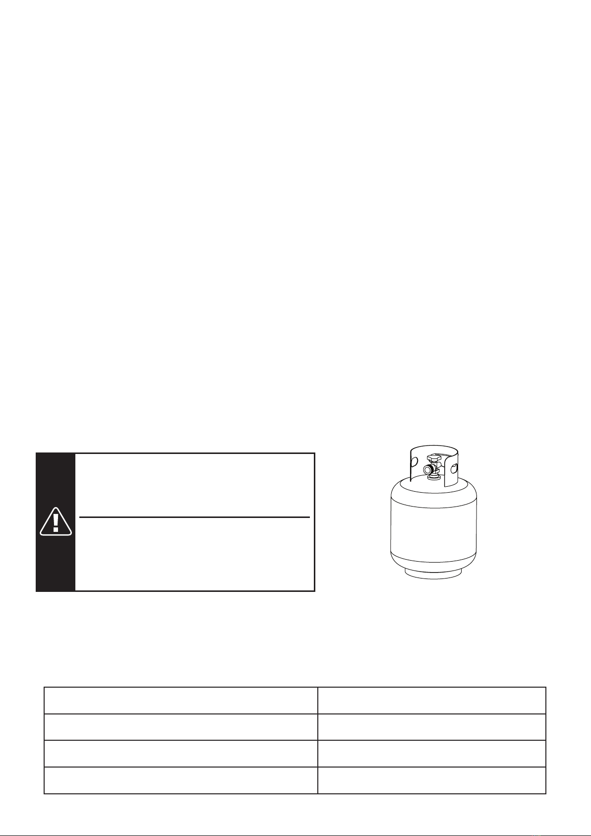
The LP-gas supply cylinder to be used must have a listed overfilling prevention device (See Figure 1).
The LP-gas supply cylinder to be used must have a cylinder connection device compatible with the
connection for the appliance.
A self-contained LP-gas cylinder for use with this appliance must have a capacity of 20 Ibs cylinder (Height
approximately 18 in., Tank Body approximately 12 in. diameter, Base approximately 8 in. diameter).
The cylinder supply system must be arranged for vapor withdrawl.
The cylinder used must include a collar to protect the cylinder valve.
This appliance shall be used only outdoors in a well-ventilated space and shall not be used in a building,
garage or any other enclosed space.
When this appliance is not in use, the gas must be turned off at the supply cylinder.
Storage of this appliance indoors is permissible only if the cylinder is disconnected and removed from the
appliance.
Cylinders must be stored outdoors in a well-ventilated area out of the reach of children.Disconnected
cylinders must have threaded valve plugs tightly installed and must not be stored in a building, garage or
anyother enclosed areas.
This appliance is certified by CSA (Canadian Standards Association) to ANSI Z21.97/CSA 2.41-2014,
Outdoor Decorative Gas Appliances.
1.
2.
3.
4.
5.
6.
7.
8.
9.
10.
11.
Standard 20 Ib.tank
Figure 1
SPECIFICATIONS
Rated Heat Input (Liquid Propane & Natural Gas)
Propane Regulator Pressure
Natural Gas Inlet Pressure
Clearance to combustible surfaces
50,000 BTU/hr
11 inches water column
7 inches water column
Sides: 24in. (610mm), Top: 72in. (1829mm)
WARNING:
FUELS USED IN LIQUEFIED PROPANE GAS
APPLIANCES, AND THE PRODUCTS OF COMBUSTION OF SUCH
FUELS, CAN EXPOSE YOU TO CHEMICALS INCLUDING BENZENE,
WHICH IS KNOWN TO THE STATE OF CALIFORNIA TO CAUSE
CANCER AND CAUSE BIRTH DEFECTS OR OTHER REPRODUCTIVE
HARM.
For more information go to: www.P65Warnings.ca.gov.
ADVERTENCIA:
LOS COMBUSTIBLES USADOS EN EQUIPOS
PARA LICUAR GASPROPANO, ASÍ COMO LOSPRODUCTOS DE SU
COMBUSTIÓN, PUEDEN EXPONERTE A SUSTANCIAS QUÍMICAS,
ENTRE ELLAS EL BENCENO, QUE EL ESTADO DE CALIFORNIA
RECONOCE COMO CAUSA DE CÁNCER Y DE MALFORMACIONES
CONGÉNITAS Y OTROS DAÑOS AL SISTEMA REPRODUCTOR.
Para más información, visite www.P65Warnings.ca.gov
05
PACKAGE CONTENTS
PART QUANTITYDESCRIPTION
A 1Tabel top assembly
B 1Right panel
C 1Left panel
D 1Door
E 1Back panel
F 1Front-right leg
G 1Back-right leg
H 1Front-left leg
I 1Back-left leg
J 1Upper beam
PART QUANTITYDESCRIPTION
K 1Bottom beam
L 1Gas cylinder support
M 4Foot glider
N 1Weather cover
O 1Handle assembly
P2 pkgLava rock (13.2 lbs)
Q 1Natural gas orifice
AA 30Bolt (M6 x 15)
BB 30Washer (M6)
CC 1Hex screw driver

06
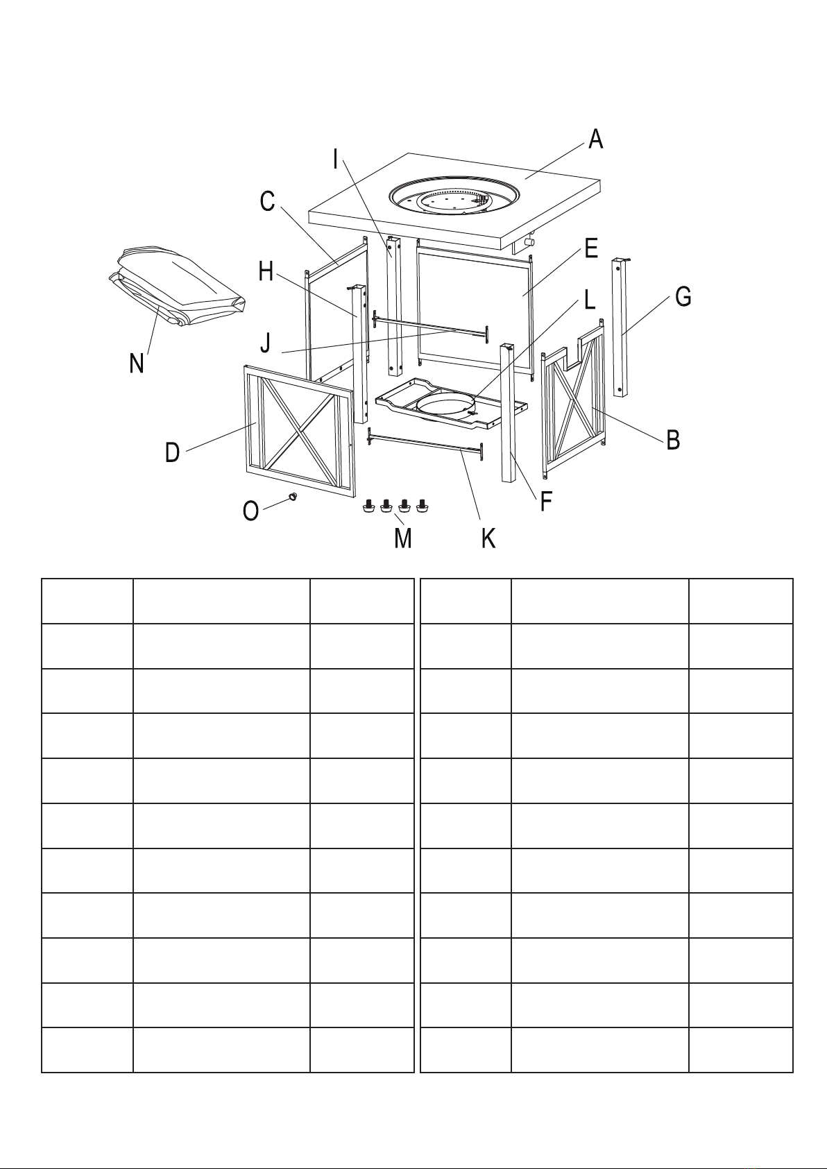
ILLUSTRATED PARTS LIST
ATable top assembly BRight panel CLeft panel
DDoor EBack panel FFront-right leg
GBack-right leg HFront-left leg IBack-left leg
JUpper beam KBottom beam LGas cylinder support
MFoot glider NWeather cover OHandle assembly
PLava rock QNatural gas orifice AA Bolt (M6 x 15)
BB Washer CC Hex screw driver
07
ASSEMBLY INSTRUCTIONS
NOTE: Tool Required for Assembly: phillips screw driver ( NOT included)
NOTE: DO NOT tighten the screws completely.
1. Carefully unpack all parts from the box, compare parts with package content listed above, make sure all
parts are present before beginning assembly of product. If any part is missing or damaged, do not attempt
to assemble the product. Contact customer service for replacement parts.
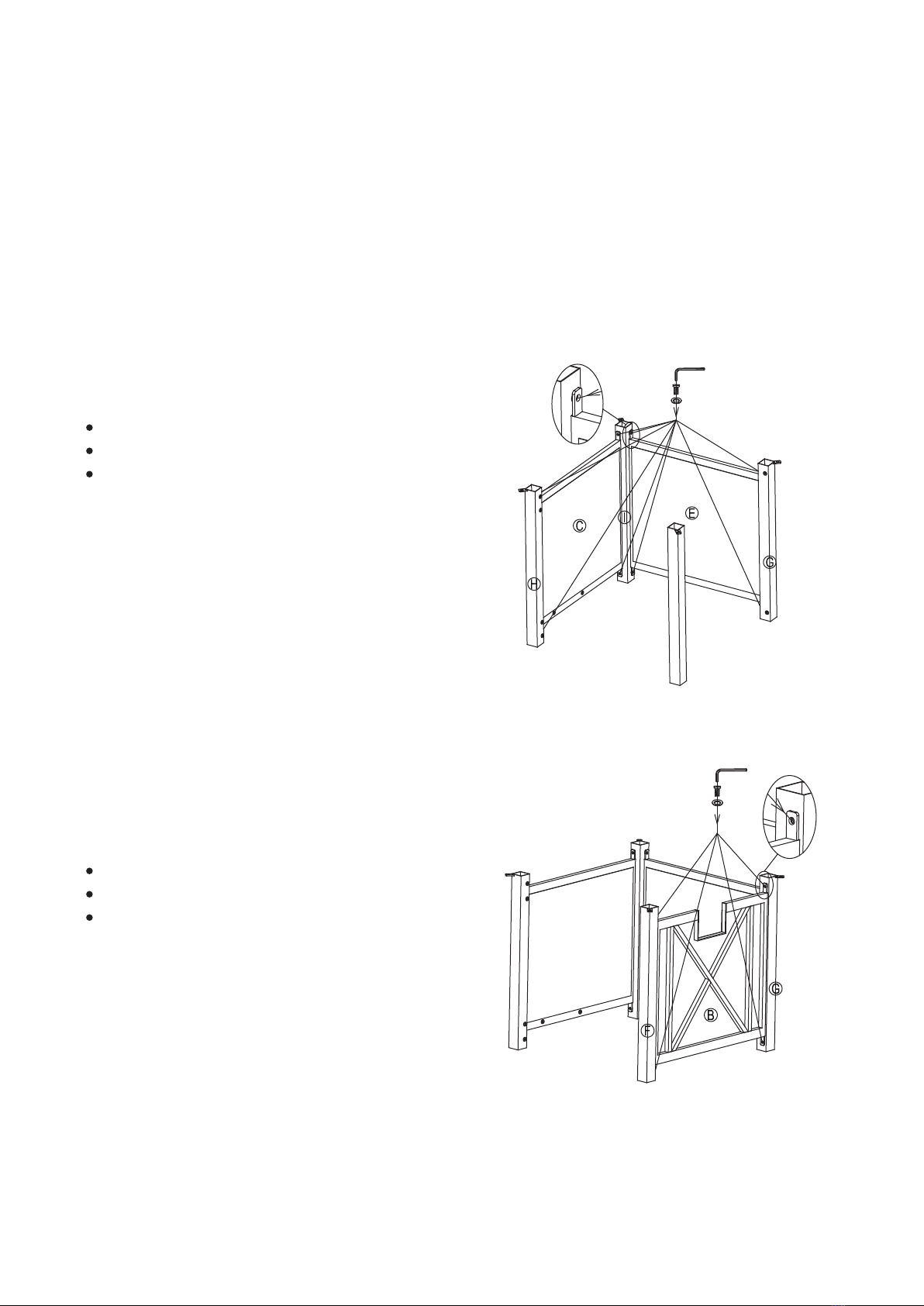
2. Attach the Left Panel (C) to Front-Left Leg (H) and Back-Left leg (I) with Bolt (AA) and Washer (BB) by using
the Hex Screw Driver (CC). Attach the Back Panel (E) to Back-Right Leg (G) and Back-Left leg (I) with Bolt
(AA) and Washer (BB) using the Hex Screw Driver (CC), (see Figure 2).
3. Attach the Right Panel (B) to Front-Right Leg (F) and Back-Right leg (G) with Bolt (AA) and Washer (BB) using
the Hex Screw Driver (CC), (see Figure 3).
4. Attach the Upper Beam (J) to the Front-Left Leg (H) and the Front-Right leg (F) with Bolt (AA) and Washer
(BB) using the Hex Screw Driver (CC). Attach the Bottom Beam (K) to the Front-Left Leg (H) and the
Front-Right leg (F) with Bolt (AA) and Washer (BB) using the Hex Screw Driver (CC), (see Figure 4).
NOTE: DO NOT tighten the screws completely.
NOTE: DO NOT tighten the screws completely.
Hardware Used:
AA Bolt (M6 x 15) x 4
BB Washer (M6) x 4
CC Hex screw driver x 1
Hardware Used:
AA Bolt (M6 x 15) x 8
BB Washer (M6) x 8
CC Hex screw driver x 1
CC
AA
BB
CC
AA
BB
Figure 2
Figure 3

08
5. Attach the Gas Cylinder Support (L) to the Right Panel (B) and the Left Panel (C) with Bolt (AA) and Washer
(BB) using the Hex Screw Driver (CC), (see Figure 5).
NOTE: DO NOT tighten the screws completely.
Hardware Used:
AA Bolt (M6 x 15) x 4
BB Washer (M6) x 4
CC Hex screw driver x 1
6. Attach the Door (D) to the Upper Beam (J) and the Bottom Beam (K) with Bolt (AA) and Washer (BB) using the
Hex Screw Driver (CC), (see Figure 6).
NOTE: DO NOT tighten the screws completely.
Hardware Used:
AA Bolt (M6 x 15) x 2
BB Washer (M6) x 2
CC Hex screw driver x 1
Hardware Used:
AA Bolt (M6 x 15) x 8
BB Washer (M6) x 8
CC Hex screw driver x 1 CC
AA
BB
CC
AA
BB
CC
AA
BB
Figure 4
Figure 5
Figure 6

09
8. Attach the assembled base to the Table Top Assembly (A) with Bolt (AA) and Washer (BB) using the Hex Screw
Driver (CC). Make sure the control panel just covers up the notch on the Right Panel (B), (see Figure8). Then
tighten all the screws completely.
9.Put the Lava Rock (P) around the burner, then remove the label from the pilot box (see Figure 9). A gas fire pit
requires 13.2 lbs lava rock. NOTE: DO NOT completely cover the burner element or block the pilot box
with the lava rocks. When the first use, preheat the lava rocks for 15 minutes to burn out the impurities
and air in the natural lava rocks.
NOTE: DO NOT tighten the screws completely.
WARNING: keep children away during assembly, as this item contains lava rock, which are small pieces and
can be swallowed by children.
Hardware Used:
AA Bolt (M6 x 15) x 4
BB Washer (M6) x 4
CC Hex screw driver x 1
7. Un-screw the Handle Assembly (O), attach the Handle to the Door (D) using the phillips screw driver, then
screw it tightly (see Figure 7).
NOTE: DO NOT tighten the screws completely.
CC
AA
BB
Figure 7
Figure 8
Figure 9
Ppilot box
FOR YOUR SAFETY: Surfaces of fire pit can remain extremely hot for
a period after use. Allow 45 minutes to cool down before touching or
moving the fire pit.
10
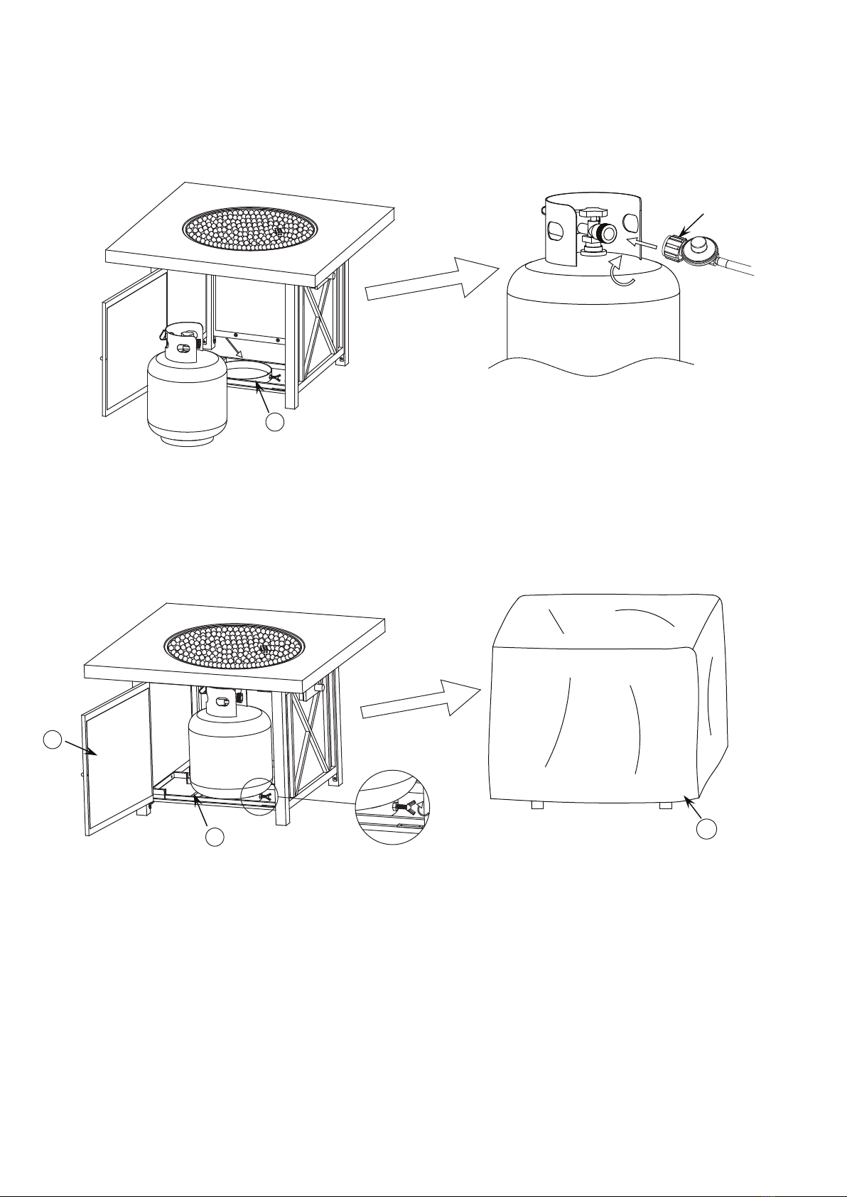
Figure 10
Figure 11
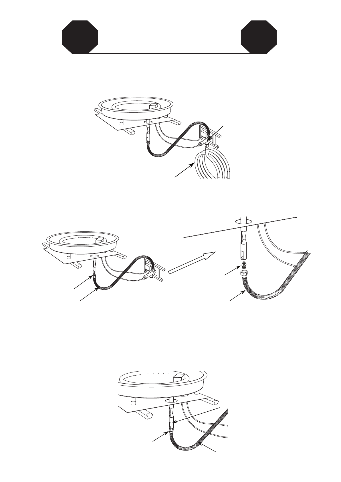
10. Open the door, place the gas cylinder into the Gas Cylinder Support (L), connect the regulator, screw the black
handle clockwise to tighten, turn the black handle counterclockwise to remove. The hose must point down. The
knob on the control panel is turned all the way to the “OFF” position when the fire pit is NOT in use(see Figure
10).
11. Secure the gas cylinder by tightening clockwise the butterfly screw found on the Gas Cylinder Support (L), so
that the gas cylinder cannot move from side to side or fall down. Close the Door (D), cover the fire pit with the
Weather Cover (N) when not in use to protect it from the elements or when fire pit is cool COMPLETELY after
the use (see Figure 11).
black handle
N
L
L
D
11
Figure 12
Figure 13
Figure 14
STOP STOP
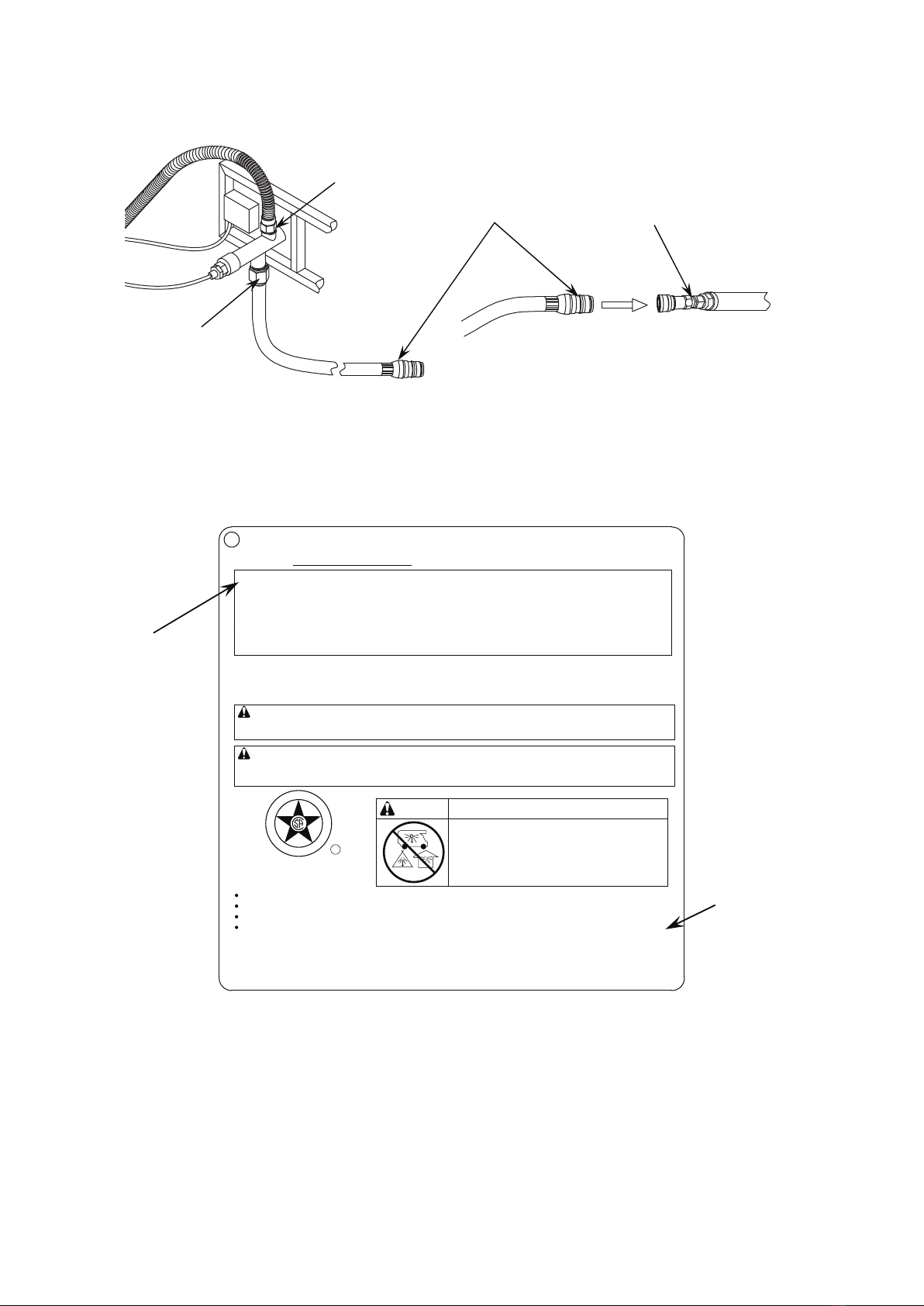
NATURAL GAS CONVERSION
Natural gas conversion must be performed only by natural gas provider or service company.
1. Disconnect the propane hose from the gas valve (see Figure 12).
2. Unscrew and disconnect the propane orifice from the bellows (see Figure 13). Propane orifice
(2.21 mm diameter size) is painted with red mark.
3. Replace the propane orifice with the natural gas orifice, screw the natural gas orifice with the bellows
tightly,then connect and tighten the natural gas orifice with inlet tube (see Figure 14). Natural gas orifice
(4.18 mm diameter size) is painted with black mark.
propane orifice
bellows
propane orifice
bellows
inlet tube
bellows
natural gas orifice
propane hose
gas valve
12
Figure 15 Figure 16
Figure 17
4. Connect the natural gas hose with the gas valve by screwing clockwise tightly (see Figure 15). Plug the
natural gas fixture into the natrual gas supply piping system (see Figure 16).
5. Stick and cover the conversion label onto the propane rating plate (see Figure 17).
gas valve
natural gas hose
conversion label
propane rating plate
natrual gas fixture
natrual gas supply
piping system
Model Number:
FW-CTGSQFP
Serial Number:
Rated Heat Input : 50,000 BTU/h
Type of Gas : Propane
DANGER
Minimum clearance from combustible constructions: Sides:24in. 610mm. Top:72in. 1829mm.
FOR OUTDOOR USE ONLY.
If stored indoors, detach and leave cylinder outdoors. Do not connect to a remote
gas supply. It is shipped with LP gas orifice. You can find the orifices on the package with LP manual. Please
follow the instructions package with the orifices for gas conversion.
CARBON MONOXIDE HAZARD
This appliance can produce carbon
monoxide which has no odor.
Using it in an enclosed space can kill you.
Never use this appliance in an enclosed
space such as a camper, tent, car or home.
Design Certified by CSA Group
ANS Z21.97/CSA 2.41-2014
Outdoor Decorative Gas Appliances
WARNING: Improper installation, adjustment alteration, service or maintenance can cause injury
before installing or servicing this equipment.
WARNING: Do not store or use gasoline, or other flammable vapors and liquids, in the vicinity of
this or any other appliance.An LP-cylinder not connected foruse shall not be stored in the vicinity of
this or any other appliance.
Gas Supply : 20-lb. LP gas cylinder
Gas Supply Pressure : Max 250 psi
Manifold Pressure : 11 inches
The instruction manual contains important information necessary for the proper assembly and safe use of the appliance.
Read and follow all warnings and instructions before assembling and using the appliance.
Follow all warnings and instructions when using the appliance.
water column
S
E
D
G
N
R
E
C
T
I
F
I
I
E
D
R
CAUTION: This appliance has been converted to use natural gas.
Propane orifice dia2.21mm, natural gas orifice dia4.18mm.
Rated Heat Input : 50,000 BTU/hr
Type of Gas : Natural gas
Max Gas Supply Pressure : 7 inches water column (1.74kPa)
Min. Gas Supply Pressure : 5 inches water column (1.24kPa)
or property damage. Read the installation, operating, and maintenance instructions thoroughly
FW-CTGSQFP

13
Figure 18
BATTERY
BATTERY
WARNING:
Make sure the control knob is in the “OFF” position. Unscrew the push button cap on the ignitor module located
on the control panel to access the battery compartment. The ignitor module requires one AAA size battery (See
Figure 18),
BATTERY IS NOT INCLUDED.
1. Please observe proper polarity and use the correct battery type when placing or replacing the battery.
Improper installation could result in ignition failure.
2. Please remove the battery if consumed or if product is to be left unused for a long period of time.
1. Always perform the leak test as described below before lighting this appliance or each time the
cylinder is connected for use.
2. Do not smoke or allow other sources of ignition in the area while conducting a leak test.
3. Conduct the leak test outdoors in a well-ventilated area.
4. Do not use matches, lighters or a flame to check for leaks.
5. Do not use this appliance until any and all leaks are corrected. If you are unable to stop a leak,
disconnect the propane supply. Call a gas appliance service shop or your local propane gas supplier.
To prevent fire or explosion hazard when testing for a leak:
cylinder-regulator connection (Figure 19) gas valve-bellows connection (Figure 20)
LIGHTING INSTRUCTIONS
1. Push in gas control knob slightly and
2. Turn gas control knob to “ON/MIN”.
3. Push in gas control knob all the way
4. If the burner does not light in 15
1. Push in gas control knob slightly and turn to “OFF”.
TO TURN OFF GAS
INSTRUCCIONES DE ENCENDIDO
PARA CERRAR EL GAS
1. Presione ligeramente la perilla de control del gas y gírela a la
2. Gire la perilla de control del gas a “ENC/MÍN” (encendido/mínimo).
3. Presione la perilla de control del gas hasta el fondo y mantenga presionada.
4. Si el quemador no se enciende en 15 segundos, suelte la perilla y esta
encender el quemador nuevamente, repita los pasos 1 al 3.
1. Presion ligeramente la perilla de control del gas y gírela a la
turn to “OFF”.
and hold. Continue to press the
ignition button for 15 seconds.
seconds, release the knob and it will
pop back out. Wait 5 minutes before attempting
to light the burner again, repeat step 1 to 3.
posición “APG” (apagado).
Siga presionando el botón de encendido durante 15 segundos.
volverá a su posición hacia afuera. Espere 5 minutos antes de intentar
posición “APG” (apagado)
OFF (APG.)
MAX
(MÁX.)
1 AAA
1.5V
IGNITOR
( Encendedor )
ON/MIN
(ENC./MÍN.)
14
LIGHTING INSTRUCTIONS
Make 2~3 oz. of leak solution by mixing one part liquid dishwashing detergent and three parts water. Noted:
make sure control knob is “OFF”.
Apply several drops of solution where the cylinder attaches to regulator (see Figure 19), inspect the solution
at the connection looking for bubbles. If NO bubbles appear, the connection is secure. If bubbles appear, the
connection has the leak, disconnect the regulator, reconnect, perform another leak check. If you continue to
see bubbles after several attempts, cylinder valve is defective and should be returned to cylinder’s supplier.
Apply several drops of solution where gas valve attaches to bellows (see Figure 20), where gas valve
attaches to hose (see Figure 21), and where inlet tube attaches to bellows (see Figure 22). If NO bubbles
appear, the connections are secure. If bubbles appear, the connection has the leak, disconnect,
reconnect,perform another leak check. If you continue to see bubbles after several attempts, the part is
defective and should replace the part.
1. Push in gas control knob slightly and turn to “OFF”.
2. Turn gas control knob the “ON/MIN”.
3. Push in gas control knob all the way and hold. Continue to press the ignition button for 15 seconds.
4. If the burner does not light in 15 seconds, release the knob and it will pop back out. Wait 5 minutes before
attempting to light the burner again, repeat step 1 to 3.
WARNING: For your safety, read and follow the Lighting Instructions in this manual and in the Rating Plate on
the appliance. IMPROPER LIGHTING PROCEDURES COULD RESULT IN A FIRE HAZARD OR
EXPLOSION HAZARD OR PROPERTY DAMAGE, INJURY OR LOSS OF LIFE.
TO TURN OFF GAS
1. Push in gas control knob slightly and turn to “OFF”.
To perform a leak test:
gas valve-hose connection (Figure 21) inlet tube-bellows connection (Figure 22)
gas control knob
ignition button
Figure 23
1.
2.
3.
15
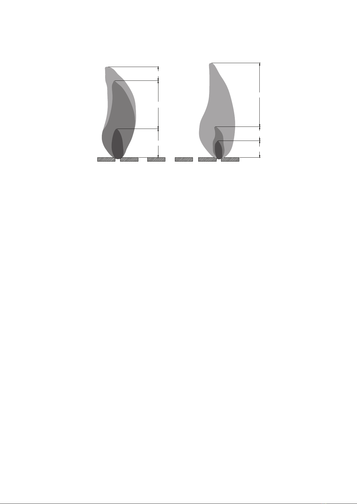
Observe Flame Height When Lit: Flame should be a blue / yellow color between 1~2 in. height (see Figure 24).
Figure 24
CARE AND MAINTENANCE
Yellow
Yellow
Light Blue
Light Blue
Blue Blue
Good Bad
To enjoy the outstanding performance from your fire pit, make sure you perform the following activities on a
regular basis:
1. Use warm soapy water for cleaning. Never use flammable or corrosive cleaning agents.
2. While cleaning the fire pit, make sure to keep the area around the burner dry at all times. DO NOT
submerge the control valve assembly. If the gas control is submerge in water, DO NOT use it. It must
be replaced.
3. Air flow must be unobstructed. Keep controls, burner, and circulating air passageways clean. Signs of
possible blockage include:
(1). Gas odor with extreme yellow tipping of flame.
(2). Fire pit does NOT reach the desired temperature.
(3). Fire pit flame is excessively uneven.
(4). Fire pit makes popping noises.
(5). Spiders and insects can nest in burner or orifice. This dangerous condition can damage fire pit and
render it unsafe for use. Clean burner holes by using a heavy-duty pipe clearer. Compressed air
may help clear away small particles.
4. Carbon deposits may create a fire hazard. Clean burner with warm soapy water if any carbon deposits
develop.
5. Cover your fire pit with an outdoor weather cover when not in use to protect it from the elements.
NOTE: Always allow fire pit to cool COMPLETELY before you cover the fire pit with an outdoor weather
cover or you attempt the service or maintenance.
16
REPLACEMENT PARTS LIST
NO PART# DESCRIPTION
01 EFP-RDTTA Table top assembly
02 EFP-RP Right panel
03 EFP-LP Left panel
04 EFP-DR Door
05 EFP-BP Back panel
06 EFP-FRLG Front-right leg
07 EFP-BRLG Back-right leg
08 EFP-FLLG Front-left leg
09 EFP-BLLG Back-left leg
10 EFP-UPBM Upper beam
11 EFP-BTBM Bottom beam
12 EFP-GCSPT Gas cylinder support
13 EFP-FOOTGD Foot glider
14 EFP-HDL Handle assembly
15 EFP-THRMCPL Thermocouple
16 EFP-PLSELT Pulse Ignition
17 EFP-CNNB Knob
18 EFP-HRDPK Hardware pack
This manual suits for next models
1
Table of contents
Popular Outdoor Fireplace manuals by other brands

Home Decorators Collection
Home Decorators Collection ST. CHARLES FHTM80273 Use and care guide

RUSTA
RUSTA EMBER manual

UKIAH
UKIAH VOYAGER manual

Aurora
Aurora ZENTAI Installation and user manual

Masport
Masport MAWSON CAMPFIRE Assembly & Usage Instructions

Backyard Creations
Backyard Creations DC13-12522 owner's manual


