AG RIAREX BT-FG01 User manual
BT-FG01
Security Smoke Generator User Manual

Introduction
Thank you for choosing BT-FG01 security smoke system. It is the most effective
and reliable security system to protect your property and premises. Please read
this instruction to ensure you have the maximum performance of your security
smoke system. If you have any question or uncertainty, please contact with your
dealer. Once again, thank you for your choice. We hope it is an equipment which
never needs to be tested in real life.
Every effort has been made to ensure the contents in this manual are correct. The factory
does not accept any liability for loss or damage caused or alleged to be caused directly
or indirectly by this manual. The factory reserves the right to change the contents in
this manual without any further notice.
Reminder: Before installation, please ensure that you have all the following items in the box:
Security Smoke Generator x 1
Mounting Wall Bracket x 1
Smoke Fluid Bag x 1
Placing or changing Fluid Bag
When placing or changing fluid bag, please ensure the fluid needle is inserted into fluid
bag completely. Locate the bag neck in the holder and ensure the fluid micro switch is
activated properly and screw the bag clamp tightly. Every time when placing a new fluid
bag, please make sure mains power is applied to smoke generator. This can allow fluid
timer be reset correctly.
Fluid Consumption Calculation and Reset
The fluid consumption is calculated and monitored by an on-board fluid timer. In order to avoid
incorrect fluid consumption calculation, every time when the bag clamp is unscrewed and the
fluid bag is removed and the fluid micro switch is released, ensure a new (full fluid bag is
replaced to reset the on-board timer.
Important: Every time when placing a new fluid bag, please make sure mains power is applied
to smoke generator. This can allow fluid timer be reset correctly!
Fluid Micro Switch
Bag Clamp
Insert Fluid Needle
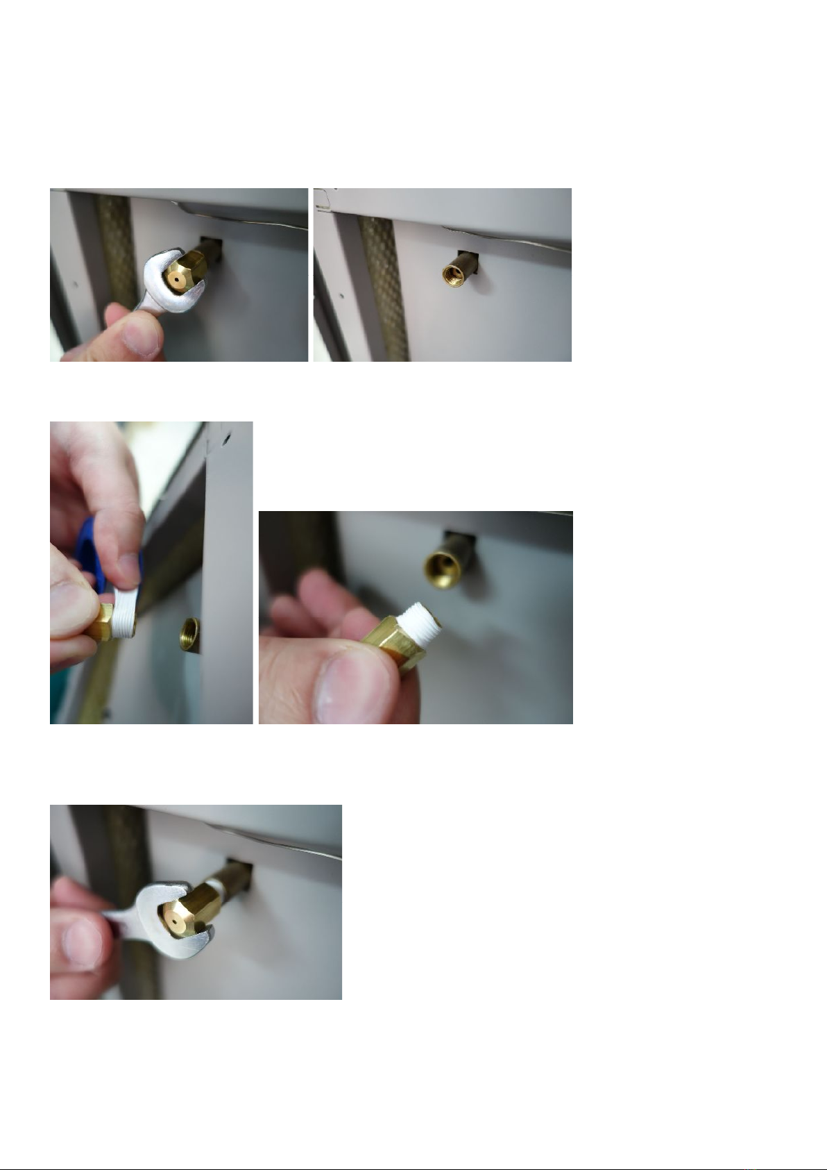
Changing Nozzles
There are interchangeable nozzles available. When a different or a new nozzle is needed,
please follow below steps to change nozzles:
Step 1. Remove the original nozzle and clean the residue inside.
Step 2. Put on the new nozzle. (Make sure the new nozzle is with Teflon tape on it.
Without Teflon tape on nozzle might cause fog leak during operation)
Step 3. Fix the new nozzle to proper tightness (around 70% tight is good enough) Please note
that tighten the nozzle too hard or completely can cause permanent damage to the heater
block.

Input & Output Connections (Terminals on PCB
The Connections (Terminals) layout of PCB is as followings diagram. We can use the 3 sets
of Input Connections on the smoke generator to make and control fog output.
There are 3 sets of Input Connections on the smoke generator (They are Alarm set, Trigger
and Hold OFF). In order to make smoke output, all 3 sets of Input Connections must
be “open circuit” at the same time. (This can be switched to “closed circuit” by selecting the
DIP Switch # 1 to “Off” position. Please see the “DIP Switch” section instruction). The
smoke generator is unable to make smoke output, if any one of these 3 sets
of Input Connections is “closed circuit”. Therefore, the production of smoke
output can be controlled by using one or a combination of the following:
*Alarm set – a normally closed relay connected across the Alarm Panel ‘Set’ connections,
which open when the alarm panel is ‘Set’ and close when the panel is ‘Unset’.
*Trigger – a normally closed relay connected across the Alarm Panel ‘Trigger’ or ‘Intruder’
connections, which open when the alarm panel is in ‘alarm’.
*Hold OFF – usually a PIR or movement sensor connected to the ‘Hold-off PIR’
connections (N/C), which open when the sensor sees movement.
Tamper
Tamper
0 V
+12 V (100 mA)
Hold OFF
Hold OFF
Verification NO
Verification NC
Verification COM
UPS status NO
UPS status NC
UPS status COM
Fluid status NO
Fluid status NC
Fluid status COM
Not ready NO
Not ready NC
Not ready COM
Trigger (intruder)
Trigger (intruder)
Alarm set
Alarm set

* Additional Hold OFF – any form of N/C relay or micro switch can be connected to
the ‘Hold-off’ connections. Where fitted in addition to the Hold-off PIR both sets of relays
must be ‘open’ to produce ‘smoke’.
There are 4 sets of Output Connections on smoke generator. They are “Status
Output”, “Liquid Status”, “Battery Output”, “Tamper Status” and “Verification Output”.
These outputs are provided for connection to the Alarm Panel.
*Fluid output
: “Fluid Output” changes state (from N/C to N/O or reverse) if fluid level is
low or empty.
*UPS output
: “UPS Output” changes state (from N/C to N/O or reverse) if UPS fails to
work correctly. (Only when an external UPS (Uninterrupted Power Supply) system is
applied. The function of UPS can be switched On/Off by DIP Switch #2.
Please see the
“DIP Switch” section instruction
*Not ready output:
“Not Ready Output” changes state (from N/C to N/O or reverse) if
“Tamper opened” or “Mains Power failed” or “Fluid empty”.
*Verification output
: “Verification Output” changes state (from N/C to N/O or reverse)
when smoke generator starts to produce smoke output.
There 1 set of DC 12V 100mA power output available for additional device (e.g. PIR,
movement detector).
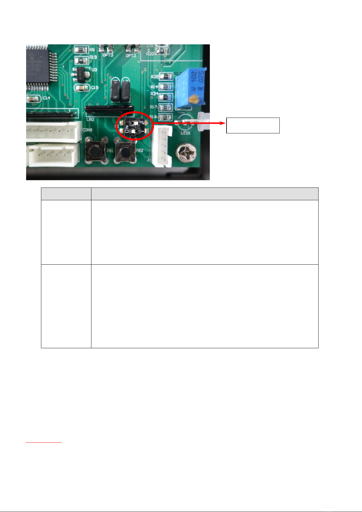
Dip Switches on PCB
Dip Switch Function
1
※Switch to “On”, machine will produce smoke output, when
“Alarm Set”, “Trigger”, and “Hold-off” these 3 sets input
connections are all “open circuit” at the same time.
※Switch to “Off”, machine will produce smoke output, when
“Alarm Set”, “Trigger”, and “Hold-off” these 3 sets input
connections are all “closed circuit” at the same time.
2
Follow below steps to switch On/Off the functions of an external
UPS (Uninterrupted Power Supply) system.
Step 1: Switch DIP Switch # 2 to “On” position. At this time, the
LED light will “Red” & “Green” flash alternately.
Step 2: Press “PB2” button for 10 seconds. At this time, the buzzer
will beep. It means the “change” (On/Off) of UPS function is done.
Step 3: Switch DIP Switch # 2 to “Off” position to complete the
setting.
Setting Smoke Time:
Step 1: Switch DIP Switch # 2 to “On” position. At this time, the LED light will “Red” &
“Green” flash alternately.
Step 2: Press “PB2” button for 5 seconds. At this time, the buzzer will beep twice.
Step 3: After the twice beep sound, each press of “PB1” button will add 15 seconds of
smoke time.
Note: The default setting is 15 seconds and the longest smoke time can be set is 6 minutes.
Important: When the smoke time is set at 6 minutes (longest), press “PB1” button once, the
smoke time will become 15 seconds (shortest).
Step 4: Switch DIP Switch # 2 to “Off” position to complete the setting.
DIP Switch

Testing Smoke Generator
Full alarm test
A full alarm test should be conducted to check that all inputs, outputs and wiring connections
to the smoke generator are correct. If a PIR or other detector is fitted, the smoke generator will
run according to the smoke time setting, once the ‘Alarm Set’, "‘Trigger’ and ‘Hold Off’ (if
applied) contacts are open. It will stop producing smoke if the ‘Alarm’ or ‘Trigger’ contacts are
closed.
Stand-alone test
When the smoke generator is ready (The green LED is permanent on), pressing the “PB1” button
can test its smoke output. The smoke generator will produce smoke output, only when the
“PB1” button is pressed. Important: This is just a “stand-alone test”, which does not check
whether the inputs and connections to the smoke generator are correct.
PB1 Test Button

LED and Buzzer indications
LED signal Machine status Buzzer signal
2 flashes every 2 seconds
It is overheating 1 short beep every 5 seconds
Cover is open
UPS power failure or UPS not connected
AC mains power fail (UPS fitted)
Heater fault
It is "Not ready"
It has in programming mode
DIP switch 2 is set to ON position
It is "Ready"
It is receiving set and trigger signals, but awaiting
hold off to activate
It has activated and smoke has been produced.
LED will continue to flash until both set and trigger
signals are reset
"LOW FLUID" - First warning
It will continue to produce smoke until "Empty".
"LOW FLUID" - Empty
It will not be able to produce smoke in this state
Flashing
On
Flashing
Flashing
On
Alternating
On
Flashing
1 flash every 2 seconds
2 flashes every 5 seconds
1 flash every 5 seconds
1 long beep every 60 seconds
3 short beeps every 30 seconds
2 short beeps every 30 seconds
1 beep every 10 seconds
Continuous beeping for 30 seconds
followed by 3 short beeps every 5
minutes
None signal
None signal
None signal
1 beep every 2 seconds
1 short beep every 5 minutes
1 long and 1 short beep every 5 minutes


C08SF0100-RIA
Table of contents
Popular Portable Generator manuals by other brands


SIGLENT
SIGLENT SSG3032X user manual

Hobart
Hobart 283782 instruction manual

Peak Scientific
Peak Scientific Infinity 1032 installation guide

Westerbeke
Westerbeke 22.0 EDE 60Hz Operator's manual

Smart Generators
Smart Generators Motorhead Plus SG13001 operating instructions

Powermate
Powermate PC0496503.17 manual