4
2.2. PROHIBITED USE
Using the machine with the following products is strictly forbidden:
Paints of any kind and type
Solvents or thinners for paints of any kind and type
Combustibles or lubricants of any kind and type
LPG or gas of any kind and type
Flammable liquids of any kind and type
Liquid foodstuffs, whether for animals or humans
Liquids containing granules or consistent solids
Mixtures of various incompatible chemical products
Liquid fertilizer or manure in suspension with lumps and/or that is particularly dense
Liquids with a temperature of over 40°C
Any products that aren’t suitable for the specific use of the machine.
2.3. USING CHEMICAL PRODUCTS
All pesticides or herbicides can be dangerous to humans and the environment if used erroneously or
inadvertently.
Therefore we recommend that only suitably trained persons should use these products (license) and in any
case only after having carefully read the instructions on the container.
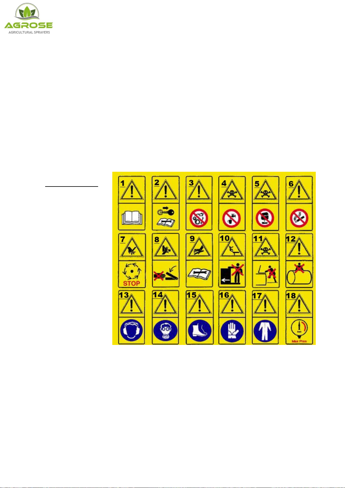
2.3.1. REGULATIONS FOR THE USE OF CHEMICAL PRODUCTS
Some recommendations for avoiding
damage and accidents:
Keep the machine in a suitable,
protected place with no access
for children or strangers
Handle the products with care,
wearing rubber acid-proof
gloves, goggles face masks or
filtering helmets, overalls made of water-repellent fabrics and boots made of rubber or similar
materials.
If chemical products or mixtures of product come into contact with the eyes or are swallowed consult
a doctor immediately, taking the label of the product with you.
Wash all clothes that come into contact with the chemical, whether diluted or undiluted, thoroughly
before using them again.
Don’t smoke, drink or eat when preparing or spraying the mix or near or in the fields treated.
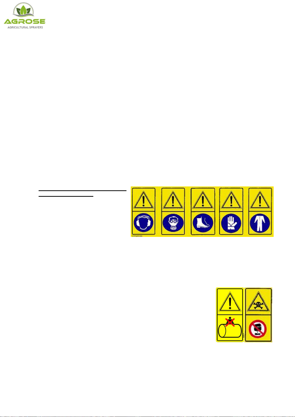
DON’T ENTER THE TANK: The residues of a chemical product can
cause poisoning and suffocation.
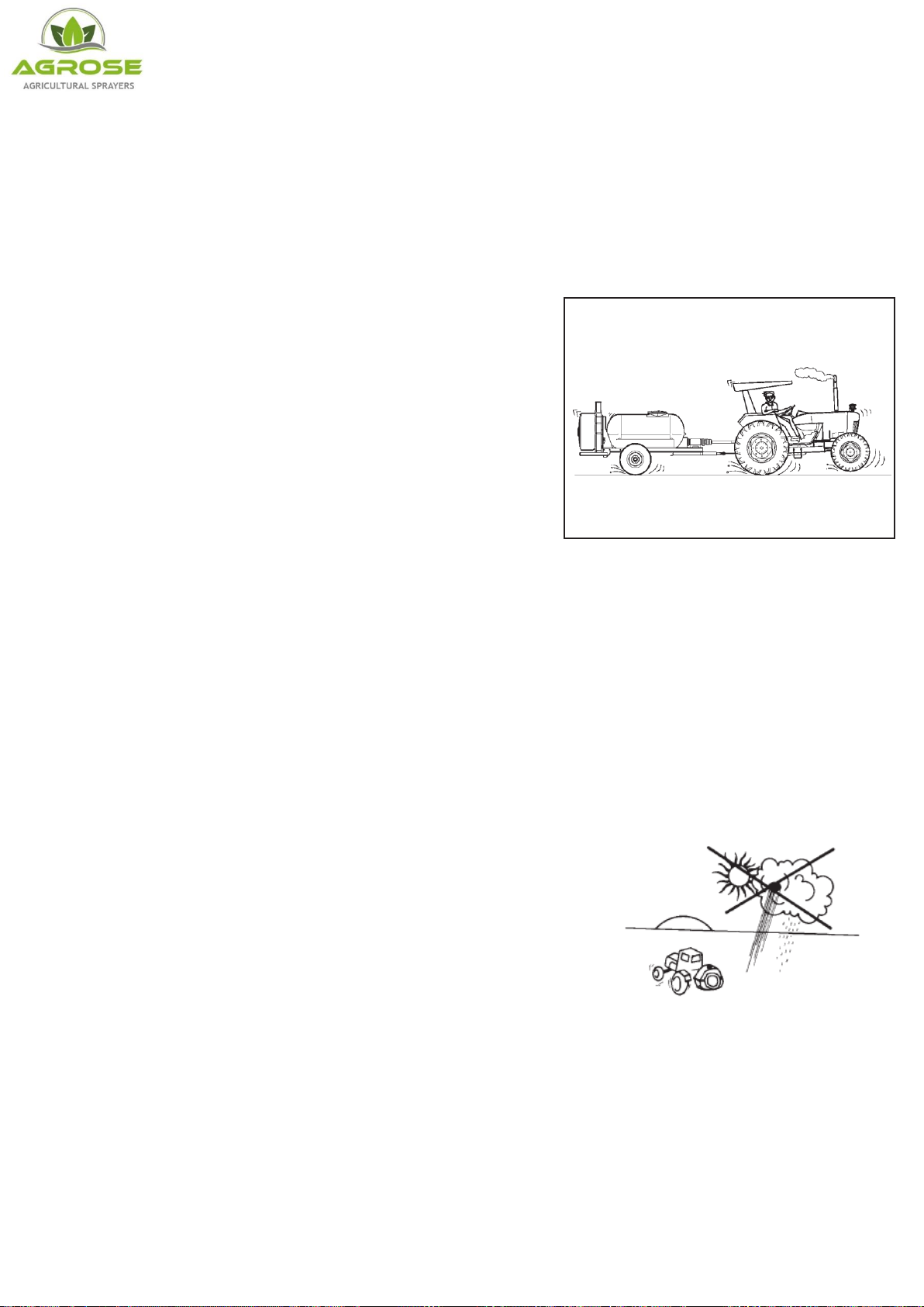
When spraying, respect safe distances from residential areas,
watercourses, roads, sports centers and public parks or paths.
Thoroughly wash the containers of plant protection products using the
relevant accessories, rinsing several times with clean water. The liquids
used for washing can be used for treatment.
Collect the washed containers and send them to the relevant collection
centers. Never dispose of them in the environment and don’t use them again for any other purpose.
It is good practice to knock a hole in the bottom of the tins so they can’t be used again.
When you have finished spraying, wash the sprayer thoroughly, diluting the residues with a quantity
of water at least 10 times that of the residues, spraying the resulting mix over the treated field.