10
LXA-7600
• Setup & Operations…
Tips for Safe Operation
+ Do not operate the amplifier with continuously glowing
CLIP LED. The respective volume control of the
channels must be adjusted so that the output level
does not clip and distort.
+ Ensure proper impedance matching. For continuous
safe operation, resultant impedance of the speakers
is recommended as 8 ohm in bridge mode and 4 or 8
ohms in mono/stereo modes.
+All connections must only be carried out or changed
with the amplifier switched OFF & the AC mains supply
disconnected.
+The amplifier must be connected to an AC earthed
mains outlet that can deliver the maximum power
required. The use of extension cables or adaptors
should be avoided as this can jeopardize correct
current delivery to the amplifier.
+ For 4 ohm applications, it is recommended to use
speakon connectors only.
+ The level of input signal should not exceed the
specified input sensitivities. Excessive input signal
levels result in over driving of input circuit which leads
to saturated / distorted output at speaker terminals.
+ Use of cable 40 / 36 or thicker is recommended to
prevent power losses in speaker cables.
+ Do not obstruct the front or rear of the amplifier for
necessary intake of air. This is a fan cooled amplifier.
LXA-7600
• Typical Applications
Stereo Mix Plus Subwoofers (LXA-3200 with LXA-7600)
11
+Connect the Left and Right High frequency output
of the active crossover to the respective input
channels A & B of amplifier 1 (LXA-3200). Inputs
can be wired as per fig. 1 & 2 (Input Connections
for Balanced and Unbalanced Mode).
+One number of full range loudspeaker system
SPX-1200 can be connected to each of the output
channels of amplifier 1. The output speakon
connectors should be wired as per fig. 3 (Output
Connections for Stereo / Mono Mode).
+One no. each of high power subwoofer system
SWX-2600 can be connected to the channel
A & B outputs of amplifiers 2 respectively. Output
speakon connectors to be wired as per fig. 4
(Output Connections for Stereo Mode).
+Amplifier 2 will be used in stereo mode. Keep the
slide switch of amplifier 2 STEREO position to
activate stereo mode.
+ Connect the Left and Right outputs of the Audio
mixing console to the respective inputs of the
Active Crossover.
+Amplifier 1 will be used in stereo mode. Keep the
slide switch of amplifier 1 in stereo position.
+Finally adjust the volume control of channel A & B
in amplifier 1 (LXA-3200) to control the level of
their respective SPX-1200.
+Also, adjust the volume control of channel A & B in
amplifier 2 (LXA-7600) to control the levels of their
respective SWX-2600.
+Operate the amplifier in such a way the clip LED
should not blink continuously.
+Continuously clip LED glow may bring amplifier
into protect mode.
+The speakon is the preferred choice for
connections, but if the output connections are to
be made on binding posts for stereo mode
applications, then (+) of the speaker should be
wired on (+) (Red) terminal of channel A output
and (-) of the speaker should be wired on (-)
(Black) terminal of the channel A output.
+Feed the left Low frequency output signal of the
crossover to the channel A input of amplifier 2
(LXA-7600). Similarly feed the Right Low
frequency output signal of the crossover to the
channel B input of amplifier 2 (LXA-7600). Inputs
can be wired as per fig. 1 & 2 (Input Connections
for Balanced and Unbalanced Mode).
Amplfiier 1 LXA-3200 (Stereo Mode)
CH. B Input CH. A Input
CH. B Output CH. A Output
Amplfiier 2 LXA-7600 (Stereo Mode)
CH. B Input
AMX-1412
PA Mixer
Microphones
R
Line Output
L
Wireless Microphone
L
L
R
R
Input
Lo Output
STEREO
ACTIVE CROSSOVER
Hi Output
Stereo Keyboard
Headphone
SPX-1200
(4W)
SPX-1200
(4W)
CH. A Output
CH. A Input
CH. B Output
SWX-2600
(4W)
SWX-2600
(4W)
L
R
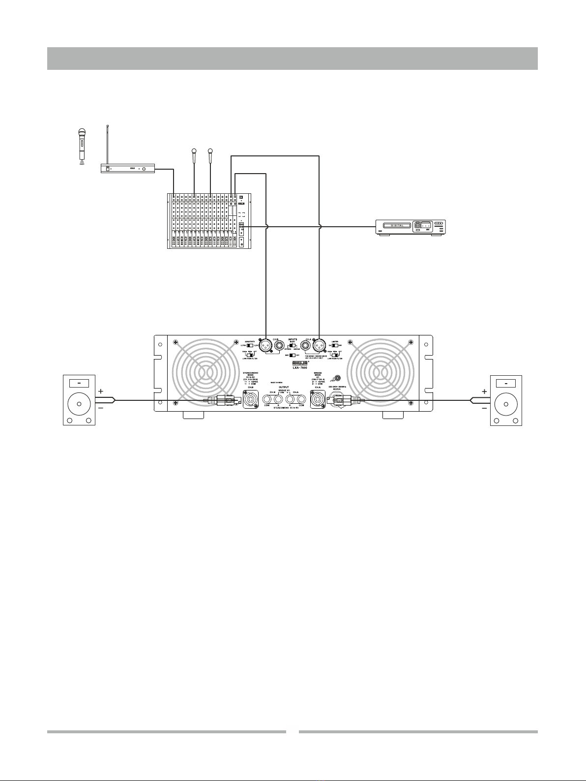
Bridge Mode Configuration
+Operate the amplifier below the clip LED glow.
+ The signal indicator LEDs glow to indicate the
presence of signal at the output terminals.
+To select bridge mode, keep the slide switch,
provided at rear, in BRIDGE position.
+The desired output levels of both the channels are
adjustable by volume control of channel A only.
+ Connect a speaker system (not below 4 ohm) on
the speakon output of channel A only. It is
recommended to use the speakon connectors and
wire these as per fig. 4 (Output Connections for
Bridge Mode).
+If however binding posts are to be used for bridge
mode then connect the positive (+) of the
loudspeaker to the positive (+) (Red) terminal of
binding posts for channel A and the negative (-) of
the loudspeaker to the positive (+) Red terminal of
Binding Post of channel B.
+ Connect the line output of a mixer to channel A
input of the amplifier. Input can be wired as per fig.
1 & 2 (Input Connections for Balanced and
Unbalanced Mode).
For BRIDGE mode operation, the signal source should be connected to the balanced / unbalanced input of
channel A only. This mode provides the combined power output of both channels for connecting a single
loudspeaker load. The recommended combined loudspeaker load should be 8 ohm.
CD Player
PA Mixer
Microphones
Play Input
Line Output
LXA-7600 CH. A Input
Multiple
Speaker System
(imp.8 ohm)
Wireless Microphone
CH. A Output