SECTION 5
Câblage
ATTENTION : VOUS ASSURER QUE L’ALIMENTATION EST
COUPÉE AU PANNEAU DE SERVICE AVANT DE COMMENCER L’INSTALLATION.
ATTENTION : TOUTES LES
CONNEXIONS DOIVENT ÊTRE FAITES EN
CONFORMITÉ AVEC LES CODES ÉLECTRIQUES LOCAUX
OU NATIONAUX. SI VOUS N’ÊTES PAS FAMILIER AVEC LES
MÉTHODES D’INSTALLATION DE CÂBLAGE ÉLECTRIQUE,
RECOURREZ AUX SERVICES D’UN ÉLECTRICIEN QUALIFIÉ.
REMARQUE : cette unité peut comporter possède un panneau
d’accès latéral pour le câblage qui ne requiert pas l’enlèvement
de l’assemblage de la soufflante du ventilateur. Si vous choisissez
de raccorder l’unité par l’intérieur, vous aurez besoin d’enlever
l’assemblage de la soufflante et le compartiment de câblage
intérieur. Les deux méthodes sont également efficaces.
1a. Compartiment de Câblage Extérieur : enlever la vis du
couvercle du compartiment à câblage et mettre ce couvercle
dans un endroit fiable (Figure 6).
1b. Compartiment de Câblage Intérieur: Enlever les trois vis
retenant en place l’assemblage de la soufflante et soulever pour
sortir l’assemblage hors du châssis (Figure 7). Enlever la vis (ou
les vis) du couvercle du compartiment à câblage et mettre ce
couvercle dans un endroit fiable (Figure 8).
REMARQUE : Si le raccord du moteur de ventilateur est raccordé au
réceptacle du châssis, le débrancher afin que l’ensemble venturi du
ventilateur soit complètement enlevé.
Modèles standards
2a. Courir le câblage d’un commutateur mural approuvé et de capacité
appropriée. Un neutre (blanc), un de mise à la terre (vert ou cuivre nu), et un
vivant (fil noir raccordé à l’interrupteur mural). Fixer les câbles électriques au châssis
avec un connecteur électrique approuvé. Vous assurer de laisser suffisamment de câble
dans la boîte pour faire le raccordement au réceptacle du ventilateur.
2b. Par là où vous avez choisi d’accéder à la boîte de jonction
du ventilateur, connecter le fil Blanc provenant de la résidence
au fil Blanc du réceptacle du ventilateur. Connecter le fil Noir
de l’interrupteur mural au fil Noir du réceptacle du ventilateur.
Connecter le fil de mise à la terre provenant de la résidence au fil
Vert du réceptacle du ventilateur (Figure 9). Utiliser des méthodes
approuvées pour toutes les connexions.
Modèles avec détection d’humidité
3a. l’emplacement du commutateur. Assurez-vous de laisser suffisamment de câblage dans
chaque boîte pour faire les connexions. À la boîte de commutation, connectez le fil noir de la
maison à la borne commune du commutateur. Connectez le fil noir du ventilateur à l’une des
bornes commutées sur le commutateur. Cette position activera le mode automatique et le
ventilateur s’activera après une élévation d’humidité. Connectez le fil jaune du ventilateur à
l’autre borne commutée sur le commutateur. Cette position activera le mode manuel et activera
le ventilateur. Connectez correctement le fil de terre et neutre (le cas échéant), installez le
commutateur et le couvercle.
3b. À partir de l’endroit où vous avez choisi d’accéder à la
boîte de jonction du ventilateur, connectez le fil blanc de la
maison au fil blanc du ventilateur. Connectez le fil de la position
automatique sur l’interrupteur mural au fil noir du ventilateur,
connectez le fil de la position manuelle sur l’interrupteur au fil
rouge du ventilateur. Connectez le fil de terre de la maison au fil
vert du boîtier du ventilateur (Figure 10). Utiliser des méthodes
approuvées pour toutes les connexions.
REMARQUE : les fils du réceptacle du ventilateur pourraient
nécessiter d’être tirés à l’extérieur du compartiment pour le
raccordement. Tirer uniquement les trois fils lâches à l’extérieur du compartiment. Des fils
additionnels y sont présents.
4. Regrouper soigneusement les fils à l’intérieur du compartiment pour le raccordement et
replacer le couvercle du compartiment en le fixant avec la vis qui fut enlevée précédemment.
SECTION 6
Complétion de l’installation
1. Il est recommandé d’utiliser un scellant approprié pour le contact avec les matériaux de
construction actuels et pour les besoins de la température de l’installation, afin d’empêcher les
fuites d’air à partir des espaces non conditionnés. S’il y a des grands écarts entre le boîtier de
l’appareil et le plafond, du matériel supplémentaire (tige de support, matériel de plafond) peut
être nécessaire.
REMARQUE : Ce ventilateur est conçu pour le contact d’isolation directe (type IC). Il est aussi
recommandé que ce ventilateur soit complètement recouvert par l’isolation afin de réduire la
perte de chaleur ou de gagner de l’espace inconditionné.
SECTION 5
Wiring
CAUTION: MAKE SURE POWER IS SWITCHED OFF AT SERVICE
PANEL BEFORE STARTING INSTALLATION.
CAUTION: ALL ELECTRICAL
CONNECTIONS MUST BE MADE IN ACCORDANCE
WITH LOCAL CODES, ORDINANCES, OR NATIONAL ELECTRICAL
CODE. IF YOU ARE UNFAMILIAR WITH METHODS OF INSTALLING
ELECTRICAL WIRING, SECURE THE SERVICES OF A QUALIFIED
ELECTRICIAN.
NOTE: This unit may include a side access panel for wiring that
does not require the removal of the fan’s blower assembly. If you
choose to wire the unit from the inside, you will need to remove
the blower assembly and internal wiring compartment. Both
methods are equally effective.
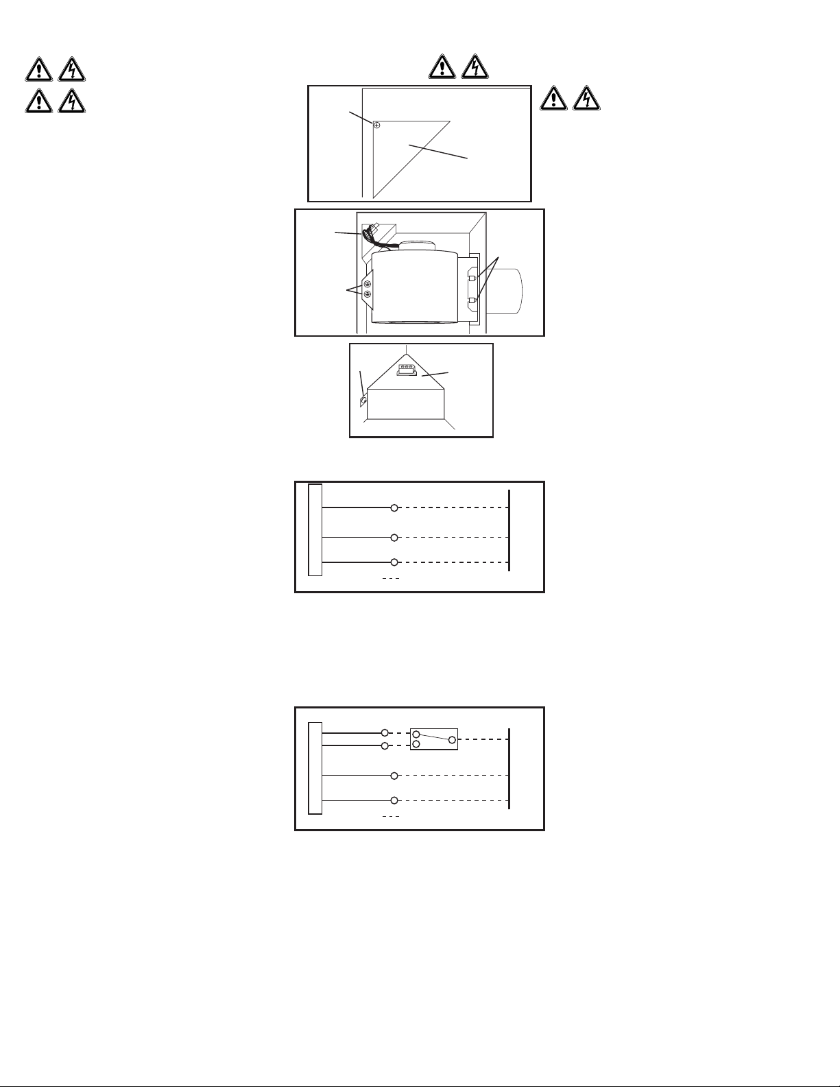
1a. External Wire Compartment: Remove the wire compartment
cover screw and place cover in a secure place (Figure 6).
1b. Internal Wire Compartment: If the motor is already installed
in the housing, remove the two screws holding the blower
assembly in place. Lift up on the assembly and slide it out
of the tabs on the housing (Figure 7). Remove the wire
compartment cover screw and place the cover in a secure
place (Figure 8).
NOTE: If the fan motor plug is connected to the fan housing receptacle, unplug
so the blower assembly can be completely removed.
Standard Models
2a. Run wiring from an approved wall switch carrying the appropriate rating.
One neutral (white), one ground (green or bare copper), and one hot (black
lead connected to the switch). Secure the electrical wires to the housing with an approved
electrical connector. Make sure you leave enough wiring in the box to make the connection
to the fan’s receptacle.
2b. From where you have chosen to access the fan’s junction
box, connect the White wire from the house to the White
wire from the fan’s receptacle. Connect the Black wire from
the wall switch to the Black wire from the fan’s receptacle.
Connect the ground wire from the house to the Green wire
from the fan’s receptacle (Figure 9). Use approved methods
for all connections.
Humidity Sensing Models
3a. For proper operation the humidity sensing fan will require a 3 way switch (not included).
Run wiring between the fan and the switch location. Make sure you leave enough wiring
in each box to make the connections. At the switch box connect the Black wire from the
house to the common terminal of the switch. Connect the black wire from the fan to one of
the switched terminals on the switch. This position will energize the automatic mode and
the fan will energize upon a rise in humidity. Connect the Yellow wire from the fan to the
other switched terminal on the switch. This position will activate the Manual On feature and
energize the fan. Properly connect the ground and neutral (if applicable) mount the switch
and the cover.
3b. From where you have chosen to access the fan’s junction
box, connect the white wire from the house to the white wire
from the fan. Connect the wire from the automatic position
on the wall switch to the black wire from the fan, connect the
wire from the manual On position on the switch to the red
wire from the fan. Connect the ground wire from the house
to the green wire from the fan housing (Figure 10). Use
approved methods for all connections.
NOTE: The fan’s receptacle wires might need to be pulled outside compartment for connection.
Only pull the three loose wires outside of compartment. Additional wires will be present.
4. Carefully tuck wire back inside wire compartment and replace wire compartment cover
securing with the screw that was removed earlier.
SECTION 6
Completing the Installation
1. Use a sealant appropriate for contact with the building materials present and for the
temperature requirements of the installation to prevent air leakage from unconditioned
spaces is recommended. If gaps between unit housing and ceiling are great, additional
material (backing rod, ceiling material) may be required.
NOTE: This fan is rated for direct insulation contact (Type IC) and it is recommended that this fan
be completely covered by insulation in order to reduce heat loss or gain to unconditioned space.
www.airkinglimited.com
6728081 Rev. J 9-20 3 of 8
Figure 6
Screw
Vis
Wire Compartment Cover
Couvercle du Compartiment
de Câblage
Figure 8
Screw
Vis
Wire Compartment
Cover
Couvercle
du Compartiment
de Câblage
Figure 9
Supply from house
Alimentation provenant
de la résidence
Neutral (White)
Neutre (Blanc)
Ground (Green or Bare)
Mise à la terre (vert ou nu)
Fan / Ventilateur
Green / Vert
Black / Noir
By others / Par d’autres
Neutral (White)
Neutre (Blanc)
Plug
Raccord
Figure 7
Screws
Vis
Tabs
Onglets
Switch / Commutateur
(by others) / (par d’autres)
Yellow / Jaune
Figure 10
Supply from house
Alimentation provenant
de la résidence
Neutral (White)
Neutre (Blanc)
Ground (Green or Bare)
Mise à la terre (vert ou nu)
Fan / Ventilateur
Green / Vert
By others / Par d’autres
Neutral (White)
Neutre (Blanc)
Black / Noir
Black / Noir