Air Lift LoadController 25850 User manual

O
Failure to read these instructions can result in an
incorrect installation.
LoadCONTROLLEY
Kits
25850
011uag
and
25854
b
y
AIR LIFT,
Single Gauge Analog
Compressor Systems
Kit #25850 with standard duty compressor
Kit #25854 with heavy duty compressor
INSTALLATION GUIDE
For maximum effectiveness and safety,
please read these instructions completely
0
before proceeding with installation.
WM-Loadcontroller Air Lift Compressor System
Rev.0
WM-Loadcontroller Air Lift Compressor System
Printed on 12/6/13
Page 1 of 20

WM-Loadcontroller Air Lift Compressor System
Rev.0
WM-Loadcontroller Air Lift Compressor System
Printed on 12/6/13
Page 2 of 20

Introduction
2
Important Safety Notice
2
Notation Explanation
2
Installation Diagram
3
Hardware List
4
Single Analog Gauge Electrical Schematic
5
Single Analog Gauge Mounting Options
6
Installing the Load Controller / Single System
7
Getting Started
7
Recommended Compressor Locations
7
Step by Step Installation
8
Standard Duty Compressor Mounting
8
Heavy Duty Compressor Mounting
8
Air Line and Power Wires Routing for the Standard Duty Compressor
9
Air Line and Power Wires Routing for the Heavy Duty Compressor
10
Product Use Information
12
Frequently Asked Questions
12
Tuning the Air Pressure
12
Guidelines for Adding Air
13
Warranty and Returns Policy
14
Replacement Information
15
Contact Information
15
WM-Loadcontroller Air Lift Compressor System
Rev.0
WM-Loadcontroller Air Lift Compressor System
Printed on 12/6/13
Page 3 of 20

A
DANGER
A
WARNING
A
CAUTION
Load Controller / Single
Introduction
The purpose of this publication is to assist with the installation of the LoadController / Single
onboard air management system.
It is important to read and understand the entire installation guide before beginning installation
or performing any maintenance, service or repair. The information here includes a hardware
list and step-by-step installation information.
Air Lift Company reserves the right to make changes and improvements to its products and
publications at any time. Contact Air Lift Company at (800) 248-0892 or visiti us online at
www.airliftcompany.com
for the latest version of this manual.
IMPORTANT SAFETY NOTICE
The installation of this kit does not alter the Gross Vehicle Weight Rating (GVWR) or payload
of the vehicle. Check your vehicle's owner's manual and do not exceed the maximum load
listed for your vehicle.
Gross Vehicle Weight Rating:
The maximum allowable weight of the fully loaded vehicle
(including passengers and cargo). This number — along with other weight limits, as well
as tire, rim size and inflation pressure data — is shown on the vehicle's Safety Compliance
Certification Label.
Payload:
The combined, maximum allowable weight of cargo and passengers that the truck
is designed to carry. Payload is GVWR minus the Base Curb Weight.
NOTATION EXPLANATION
Hazard notations appear in various locations in this publication. Information which is
highlighted by one of these notations must be observed to help minimize risk of personal injury
or possible improper installation which may render the vehicle unsafe. Notes are used to help
emphasize areas of procedural importance and provide helpful suggestions. The following
definitions explain the use of these notations as they appear throughout this guide.
INDICATES IMMEDIATE HAZARDS WHICH WILL RESULT IN SEVERE PERSONAL
INJURY OR DEATH
.
INDICATES HAZARDS OR UNSAFE PRACTICES WHICH COULD RESULT IN SEVERE
PERSONAL INJURY OR DEATH.
INDICATES HAZARDS OR UNSAFE PRACTICES WHICH COULD RESULT IN DAMAGE
TO THE MACHINE OR MINOR PERSONAL INJURY.
NOTE
Indicates a procedure, practice or hint which is important to highlight.
2
MN-750
WM-Loadcontroller Air Lift Compressor System
Rev.0
WM-Loadcontroller Air Lift Compressor System
Printed on 12/6/13
Page 4 of 20

Load Controller I
Installation Diagram
Analog Single Gauge
Adapter
Power Wire
Fuse Adapter
— Fuse Box
Fuse
* Uses 3/16 (smaller) Female Push On Connector
NOTE: THIS IS NOT AN
ELECTRICAL SCHEMATIC
BUT A LAYOUT OF THE
CONTROL SYSTEM. SEE
PAGE 5 FOR ELECTRICAL
DIAGRAMS.
In Line
15 amp Fuse
Grommet
Harness —
Relay
fis
Air Springs
(previously installed)
Ground
(A1) Standard Duty Compressor
Low Pressure
Sensor
Firewall
.1
■
11
■
111.
rommilr•
Adapter #3 *
Adapter #1
or
Adapter #2
Inflation Valve
Filter
Leader Hose Compression Fitting Power wire
Grounc
(A2) Heavy Duty Compressor
MN-750
WM-Loadcontroller Air Lift Compressor System
Rev.0
WM-Loadcontroller Air Lift Compressor System
Printed on 12/6/13
Page 5 of 20

Load Controller / Single
Hardware List
Item
Part #
Description
Qty
Al
16060
Standard Duty Compressor
1
A2 16092
Heavy Duty Compressor
1
B
25194
Analog Single Gauge
1
C
26512
Harness, Single Analog Gauge
1
D
21952
Tee, 1/8 FNPT X 1/4 PTC
1
E
24558
Sensor, 5 PSI
1
F
20946
1/4" Air Line, "DOT"
25'
G
25196
Gauge Mounting Kit
1
H
10463
Grommet
1
I
24652
Spade Fuse, 15 Amp (ATC)
1
J
24539
Fuse Holder (ATC/ATO)
1
K
24752
Center Butt, 12-10 GA Shrink Tube
2
L
24524
3/16" Terminal. FSpd
1
M
24595
FSpd Terminal, 12 GA
1
N
24543
Fuse, AGC Tap In
1
O
24561
Mini Fuse Adapter
1
P
24542
ATC/ATO Fuse Tap In 1/4
1
Q
24594
1/4" Terminal, FSpd 16 GA
4
R
10466
8" Zip Tie
5
S
21838
Tee Union 1/4" X 1/4" PTC
3
T
17441
#8-18X1" Tek Screw
2
Missing or damaged parts? Call Air Lift customer
service at (800) 248-0802 for a replacement part.
4
Mr% -75C
WM-Loadcontroller Air Lift Compressor System
Rev.0
WM-Loadcontroller Air Lift Compressor System
Printed on 12/6/13
Page 6 of 20

OSCO1V
09001V
CINCIOND SISSVH3
LOO1V
4902 NNId
VDOI NNId
33NVd 3sn4 NI 63/11:1d NOLLINDI+
VSI V
170
01V
Ot001V
4902
NNId
NN3380
CI321
NOV1E{
3D1IV9
313IH3A 3H1 3QISNI 313IH3A 3H1 3aisino
83A0d 3DflVD
ONIIHDI1N3VEI Jonvo
1VNOIS
21OSS3e1d1103
NCIOND 3011V9
VDO
8
2
WM-Loadcontroller Air Lift Compressor System
Rev.0
WM-Loadcontroller Air Lift Compressor System
Printed on 12/6/13
Page 7 of 20

Power Wires
Airline
irrwm,,
x
„
it
1
,--
6
-
Optional Dashboard Mounting
-
1
‘-g
-
(Exploded View)
Load Controller / Single
Single Analog Gauge Mounting Options
Single analog gauge mounting
hardware on bottom of gauge Single analog gauge mounting
hardware on top of gauge
fig.
5
Back of analog gauge
6
MN-750
WM-Loadcontroller Air Lift Compressor System
Rev.0
WM-Loadcontroller Air Lift Compressor System
Printed on 12/6/13
Page 8 of 20

Load Controller / Single
Installing the Load Controller
ag
e System
GETTING STARTED
This part of the installation should be done after the air spring kit is installed. If you
have any questions, please call Air Lift customer service at (800) 248-0892.
If you are adding this control system to an Air Lift LoadLifter5000 application, then no
modifications to the low pressure sensor are necessary. If you are adding this control system
to an Air Lift 1000 or RideControl application, and if your specific application requires a
minimum of 10 p.s.i., then it will be necessary to adjust the low pressure sensor to 10 p.s.i.
To increase the pressure in
the low pressure sensor,
remove the rubber plug with pliers
(fig. 7). Using an alien wrench, turn the screw clockwise 4
1
/4 turns (fig. 8). Push the rubber
plug back into the top of the low pressure sensor. Proceed with the step by step installation
instructions.
Turn alien screw 4 'A
turns clockwise
RECOMMENDED COMPRESSOR LOCATIONS
Important
LOCATE COMPRESSOR IN DRY, PROTECTED AREA ON VEHICLE.
DIRECT SPLASH OR EXCESSIVE MOISTURE CAN DAMAGE
THE COMPRESSOR AND CAUSE SYSTEM FAILURE.
Disclaimer: If you choose to mount the compressor outside the vehicle please keep in
mind the compressor body must be shielded from direct splash and the intake should be
snorkeled inside the vehicle. If the compressor does not include a remote mount air filter or
if mounting the compressor outside the vehicle, make sure to orient the compressor intake
filter so that all moisture can easily drain.
Please also remember...
•
To avoid high heat environments
•
To avoid mounting the compressor under the hood.
•
To check to be sure the compressor harness #2 will reach the compressor and connect
to harness #1.
The compressor can be mounted in any position — vertical, upside down, sideways, etc.
(please refer to the instruction manual).
MN-750
7
Remove
rubber cap
WM-Loadcontroller Air Lift Compressor System
Rev.0
WM-Loadcontroller Air Lift Compressor System
Printed on 12/6/13
Page 9 of 20

ff
Load Controller / Single
STEP BY STEP INSTALLATION
We recommend that you install the air spring kit first per the instructions provided with the
air spring kit.
J
1111111
fig•
9
Black (ground)
Compressor side
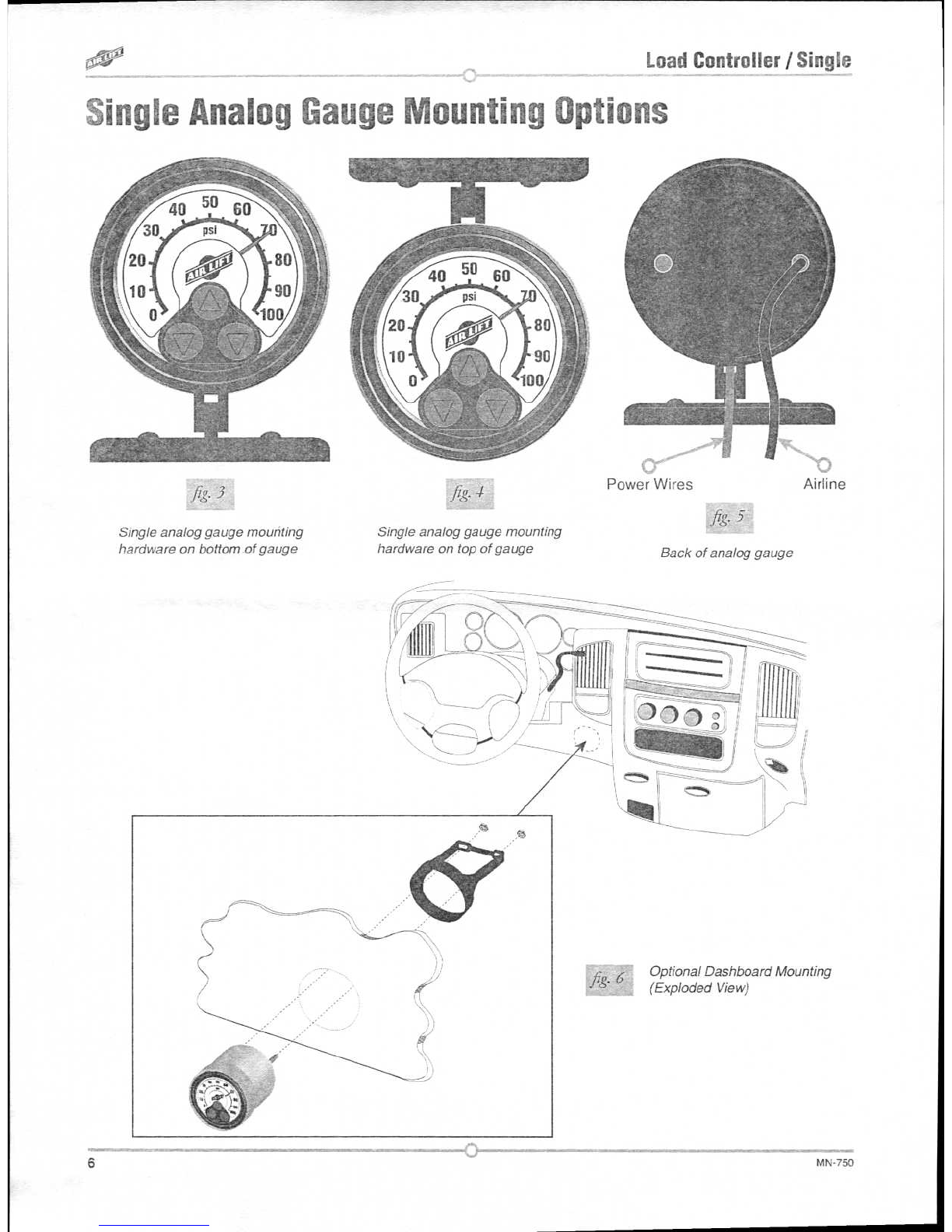
1. Install the gauge pod (figs. 3, 4 & 5). Select a convenient mounting location that has a
sturdy rigid surface. The bottom edge of the dash on either side of the steering wheel is
a good location. Attach the gauge pod to the selected location with the black self-tapping
screws.
NOTE
Optional dash mounting bracket and hardware also included (fig. 6).
2. Connect the harness to the gauge pod.
a.
Connect the color coded wires to the gauge harness as shown in the attached
schematic.
b.
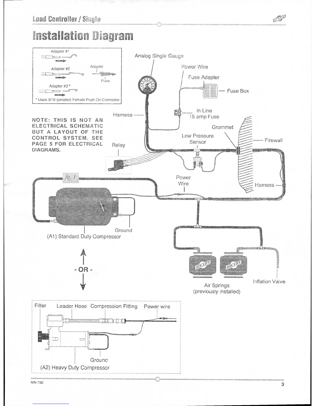
Connect the low pressure switch assemblies as shown in figures 2 and 9.
c.
Do not connect the power wire at this time.
d.
The wiring harnEss also connects the gauge pod to the low pressure sensor assembly.
The low pressure sensor protects the air springs from failure resulting from low
pressure in the unloaded condition. This sensor is preset to maintain a MINIMUM
pressure of 5 psi in the air springs unless the setting was changed in the "Getting
Started" section. The sensor measures the pressure in each spring and turns on the
compressor if the pressure falls below the set psi.
e.
Screw ground eyelet to firewall or other electrical ground in the cab.
NOTE
The sensor should be located under the dash inside the vehicle and secured with the
provided tie straps.
3. Install the compressor unit.
a.
Hold the compressor in the recommended location (fig. 10 or 11).
b.
For box frames: In some cases the frame section will not be wide enough to mount
the compressor legs flat to the rail. Refer to figs. 10 and 11 in this situation.
DO NOT DRILL ANY HOLES INTO THE FRAME OR THE FLOOR BOARD BEFORE
CHECKING FOR HYDRAULIC LINES, GAS LINES, AND/OR ELECTRICAL WIRES
THAT MAY NEED TO BE MOVED ASIDE. ALSO, WHEN ATTACHING TO THE FLOOR
BOARD, IT IS IMPORTANT TO CHECK WHERE THE SCREWS PROTRUDE THROUGH
THE FLOOR BOARD. IT MAY BE NECESSARY TO TRIM OR COVER THE TOP OF THE
SCREWS INSIDE THE VEHICLE. A SEALER SHOULD BE USED AROUND THE SCREW
TO PREVENT THE ELEMENTS FROM ENTERING THE CAB AREA.
A
CAUTION
STANDARD DUTY COMPRESSOR MOUNTING (FIG. 1 - A1, 10)
NOTE
In some cases the mounting area does not provide enough room to use a drill to drive in
the screws. It may be necessary to use the mounting brackets as a template to drill 13/64"
holes through the frame first and then use a 7/16" nut driver to install the self tapping screws.
8
MN-750
WM-Loadcontroller Air Lift Compressor System
Rev.0
WM-Loadcontroller Air Lift Compressor System
Printed on 12/6/13
Page 10 of 20

Floor plan
Load Controller / Single
Frame
Floor plan
pv
I g-
L-bracket
Supplied self
tapping screw
J/4" Bolt and nut will need to be provided if the L-bracket is
fabricated. The L bracket is shown as an optional mounting
method and is not supplied.
HEAVY DUTY COMPRESSOR MOUNTING (FIG. 1 - A2, 11)
NOTE
Using the compressor as a template, drill holes and mount the compressor using the black
mounting hardware that comes in the box containing the compressor.
Frame
NOTE
Attach the compressor ground wire to one of the mounting screws (fig. 1).
AIR LINE AND POWER WIRES ROUTING FOR
THE STANDARD DUTY COMPRESSOR:
1. Push the air line onto the barb fitting on the compressor. Make sure the air line covers
all barbs. A small amount of water or lubricant and pushing with a slight circular motion
will ease installation (fig. 12).
Air line
-
flu 12
Power (red) wires
Barbed fitting/
check valve
MN-750
9
WM-Loadcontroller Air Lift Compressor System
Rev.0
WM-Loadcontroller Air Lift Compressor System
Printed on 12/6/13
Page 11 of 20

After the hole is drilled and before
you route the harness to through the
firewall, insert the grommet and "walk"
the material around the inside edge of
the drilled hole. You may have to trim
the grommet to get an exact fit.
(The flexible grommet is in the sealed
parts package.)
Load Controller / Single
AIR
LINE AND
POWER WIRE ROUTING FOR
THE HEAVY DUTY COMPRESSOR:
Filter
Leader Hose Compression Fitting Power wire
fig-
13
Ground
(A2) Heavy Duty Compressor
1. Remove the nut from the leader hose and install over air line from check valve assembly.
2. Push the air line from the check valve assembly into the barbed fitting on the compressor
leader hose
.
3. Slide the nut over the fitting and tighten securely (fig. 13).
4. Route the harness to the compressor.
a. Use existing grommets in the floorboard or firewall to route the harness from the cab
to the frame mounted compressor.
b.
In some cases, a hole may have to be drilled to allow access for the harness. Drill
a 1" diameter hole and install the provided grommet (fig. 14). It will be necessary to
seal any grommets or holes that have been cut, drilled or removed so as not to allow
elements to enter the cab area of the vehicle.
c.
When routing the wiring harness, it should not be routed so as to lay on, or near,
the exhaust pipe/muffler/catalytic convertor of the vehicle. Routing along the top of
a crossmember or over a heat shield is recommended.
5. The next connection is between each air spring and the air line "T' fitting.
a.
With the air springs deflated, use a hose cutter to cut the air line already installed
between the air springs and the inflation valves.
b.
Install the provided "T" fittings (fig. 1) by pushing the air line into each leg of the '7"
until you feel a definite "click". Each line should go in 9/16".
c.
Connect a single length of air line to the open leg of the "T". Connect as shown in
the pneumatic schematic.
d.
Route the air line across the chassis from the far side over the exhaust system heat
shields and along the frame up to the compressor. Avoid heat sources, sharp edges,
and tight bends.
10
MN-750
WM-Loadcontroller Air Lift Compressor System
Rev.0
WM-Loadcontroller Air Lift Compressor System
Printed on 12/6/13
Page 12 of 20

Load Controller / Single
e.
Route air lines into cab from "T" fitting and attach to pressure switch assembly as
shown in the pneumatic schematic.
f.
Route air lines from low pressure switch to gauge barb.
g.
Press air line over gauge barb. Water or lube may assist in securing air lines over
the barb. A circular motion will assist in installation.
6. Connect the power wire to fused ignition.
a.
Route it to the vehicle fuse box.
b.
Determine which open terminal (accessory, etc.) works only when the key is in the
"on" or accessory position (or refer to the owners manual for an available accessory
fuse). The terminal should have an amperage rating higher than the 15 amp in-line
fuse.
c.
Connection to the fuse terminal will depend on what type of fuse your vehicle uses.
If your vehicle uses the barrel type fuse, use adapter #1. If you have the standard
spade type fuses, use adapter #2. Many late model vehicles use a smaller spade
type fuse which requires adapter #3 (fig. 15). If adapter #1 or #2 are used, it will be
necessary to cut off the 1/4" female connector attached to the power wire and crimp
the smaller 3/16" female connector supplied with this kit.
Adapter #1
Adapter #2
Adapter
••••
►
Fuse
Adapter #3 *
* Uses 3/16 (smaller) Female Push On Connector
NOTE
Connect adapter to "HOT" side of the fuse. With the ignition on, the compressor will turn on
and fill the system to 10 p.s.i. before shutting off.
7. Press the off/on button to inflate both air springs and use the small deflate button to
adjust the pressure. Inflate to 30 p.s.i. (20 p.s.i. for Air Lift 1000 kits). Check all fittings
and inflation valve cores with a solution of 1/5 dish soap to 4/5 water in a spray bottle
for leaks.
IMPORTANT:
If the compressor runs continually or often, then there is a leak. Disconnect
the compressor at the fuse box and test for leaks with a soapy water solution.
NEVER RUN THE COMPRESSOR LONGER THAN FOUR MINUTES CONTINUOUSLY.
ALLOW AT LEAST FIVE MINUTES FOR COOL DOWN BEFORE STARTING THE
COMPRESSOR AGAIN.
A
CAUTION
MN-750
11
WM-Loadcontroller Air Lift Compressor System
Rev.0
WM-Loadcontroller Air Lift Compressor System
Printed on 12/6/13
Page 13 of 20

fr
s.
16 Bad headlight aim
Rough ride
-
Sway and body roll
fig
17
fig.
18
MN-750
12
Load Controller /
Single
Product Use Information
Frequently asked question
Q. Will installing air springs increase the weight ratings of a vehicle?
No. Adding air springs will not change the weight ratings (GAWR, GCWR and/or GVWR)
of a vehicle. Exceeding the GVWR is dangerous and voids the Air Lift warranty.
Q. Is it necessary to keep air in the air springs at all time and how much pressure
will they need?
The minimum air pressure should be maintained
at all times.
The minimum air pressure
keeps the air spring in shape, ensuring that it will move throughout its travel without
rubbing or wearing on itself.
Q. Is it necessary to add a compressor system to the air springs?
No. Air pressure can be adjusted with any type of compressor as long as it can produce
sufficient pressure to service the springs. Even a bicycle tire pump can be used, but
it's a lot of work.
Q. How long should air springs last?
If the air springs are properly installed and maintained they can last indefinitely.
Q. Will raising the vehicle on a hoist for service work damage the air springs?
No. The vehicle can be lifted on a hoist for short-term service work such as tire rotation
or oil changes. However, if the vehicle will be on the hoist for a prolonged period of time,
support the axle with jack stands in order to take the tension off of the air springs.
Tuning the air pressure
Pressure determination comes down to three things — level vehicle, ride comfort, and
stability.
1.
Level vehicle
If the vehicle's headlights are shining into the trees or the vehicle is leaning to one side,
then it is not level (fig. 16). Raise the air pressure to correct either of these problems
and level the vehicle.
2.
Ride comfort
If the vehicle has a rough and harsh ride it may be due to either too much pressure or
not enough (fig. 17). Try different pressures to determine the best ride comfort.
3.
Stability
Stability translates into safety and should be the priority, meaning the driver may need
to sacrifice a perfectly level and comfortable ride. Stability issues include roll control,
bounce, dive during braking and sponginess (fig. 18). Tuning out these problems
usually requires an increase in pressure.
WM-Loadcontroller Air Lift Compressor System
Rev.0
WM-Loadcontroller Air Lift Compressor System
Printed on 12/6/13
Page 14 of 20

Unlevel
Level
fig.
20
Bottoming out
Load Controller I Single
Guidelines for adding air:
1.
Start with the vehicle level or slightly above.
2.
When in doubt, always add air.
3.
For motorhomes, start with 50-100 p.s.i. in the rear because it can be safely assumed
that it is heavily loaded.
4.
If the front of the vehicle dives while braking, increase the pressure in the front air
bags, if equipped.
5.
If it
is ever suspected that the air bags have bottomed out, increase the pressure (fig.
19).
6.
Adjust the pressure up and down to find the best ride.
7.
If the vehicle rocks and rolls, adjust the air pressure to reduce movement.
8.
It may be necessary to maintain different pressures on each side of the vehicle. Loads
such as water, fuel, and appliances will cause the vehicle to be heavier on one side
(fig. 20). As much as a 50 p.s.i. difference is not uncommon.
13
WM-Loadcontroller Air Lift Compressor System
Rev.0
WM-Loadcontroller Air Lift Compressor System
Printed on 12/6/13
Page 15 of 20

Load Controller / Single
Warranty and Returns Policy
Air Lift Company warrants its products, for the time periods listed below, to the original
retail purchaser against manufacturing defects when used on catalog-listed applications on
cars, vans, light trucks and motorhomes under normal operating conditions for as long as
Air Lift manufactures the product. The warranty does not apply to products that have been
improperly applied, improperly installed, used in racing or off-road applications, used for
commercial purposes, or which have not been maintained in accordance with installation
instructions furnished with all products. The consumer will be responsible for removing
(labor charges) the defective product from the vehicle and returning it, transportation costs
prepaid, to the dealer from which it was purchased or to Air Lift Company for verification.
Air Lift will repair or replace, at its option, defective products or components. A minimum
$10.00 shipping and handling charge will apply to all warranty claims. Before returning
any defective product, you must call Air Lift at (800) 248-0892 in the U.S. and Canada
(elsewhere, (517) 322-2144) for a Returned Materials Authorization (RMA) number.
Returns to Air Lift can be sent to: Air Lift Company • 2727 Snow Road • Lansing, MI •
48917.
Product failures resulting from abnormal use or misuse are excluded from this warranty. The
loss of use of the product, loss of time, inconvenience, commercial loss or consequential
damages is not covered. The consumer is responsible for installation/reinstallation (labor
charges) of the product. Air Lift Company reserves the right to change the design of any
product without assuming any obligation to modify any product previously manufactured.
This warranty gives you specific legal rights and you may also have other rights that vary
from state-to-state. Some states do not allow limitations on how long an implied warranty
lasts or allow the exclusion or limitation of incidental or consequential damages. The above
limitation or exclusion may not apply to you. There are no warranties, expressed or implied
including any implied warranties of merchantability and fitness, which extend beyond this
warranty period. There are no warranties that extend beyond the description on the face
hereof. Seller disclaims the implied warranty of merchantability. (Dated proof of purchase
required.)
Air Lift 1000
Lifetime Limited
LoadController/Dual
2 Year Limited
RideControl
Lifetime Limited
Load Controller (I)
2 Year Limited
LoadLifter 5000*
Lifetime Limited
Load Controller (II)
2
Year Limited
SlamAir
Lifetime Limited SmartAir
2 Year Limited
AirCel I
Lifetime Limited
Wireless AIR
2 Year Limited
Air Lift Performance**
1 Year Limited
WirelessONE
2 Year Limited
LoadController/Single
2 Year Limited
Other Accessories
2 Year Limited
*formerly SuperDuty
*`formerly LifeStyle & Performance and EasyStreet
14
MN-750
WM-Loadcontroller Air Lift Compressor System
Rev.0
WM-Loadcontroller Air Lift Compressor System
Printed on 12/6/13
Page 16 of 20

Load Controller I Single
Replacement Information
If you need replacement parts, contact the local dealer or call Air Lift customer service at
(800) 248-0892. Most parts are immediately available and can be shipped the same day.
Contact Air Lift Company customer service at (800) 248-0892 first if:
•
Parts are missing from the kit.
•
Need technical assistance on installation or operation.
•
Broken or defective parts in the kit.
•
Wrong parts in the kit.
•
Have a warranty claim or question.
Contact the retailer where the kit was purchased:
•
If it is necessary to return or exchange the kit for any reason.
•
If there is a problem with shipping if shipped from the retailer.
•
If there is a problem with the price.
Contact Information
If you have any questions, comments or need technical assistance contact our customer
service department by calling (800) 248-0892, Monday through Friday. For calls from outside
the USA or Canada, our local number is (517) 322-2144.
For inquiries by mail, our address is
PO Box 80167, Lansing, MI 48908-0167. Our shipping
address for returns is 2727 Snow Road, Lansing, MI 48917.
www.airliftcompany.com
.
MN-750
15
WM-Loadcontroller Air Lift Compressor System
Rev.0
WM-Loadcontroller Air Lift Compressor System
Printed on 12/6/13
Page 17 of 20

WM-Loadcontroller Air Lift Compressor System
Rev.0
WM-Loadcontroller Air Lift Compressor System
Printed on 12/6/13
Page 18 of 20

C
0
.
0
Ca
0
WM-Loadcontroller Air Lift Compressor System
Rev.0
WM-Loadcontroller Air Lift Compressor System
Printed on 12/6/13
Page 19 of 20

Jeed Help?
Contact our customer service department by calling
(800) 248-0892. Monday through Friday. For calls
from outside the USA or Canada, our local number
is (517) 322-2144.
Register your warranty online at
www.airliftcompany.com/warranty
Thank you for
purchasing Air Lift products — the professional installer's choice!
Air Lift
•
2727 Snow Road • Lansing, MI 48917 or PO Box 80167 • Lansing. MI 48908-0167
°
ir „ompany
Toll Free (800) 248-0892 • Local (517) 322-2144 • Fax (517) 322-0240 • www.airliftcompany.com
(.
.1.
) Printed in
the USA
WM-Loadcontroller Air Lift Compressor System
Rev.0
WM-Loadcontroller Air Lift Compressor System
Printed on 12/6/13
Page 20 of 20
Other manuals for LoadController 25850
1
This manual suits for next models
1
Table of contents
Other Air Lift Car Spares manuals