AIREDALE Barkell Therm X HR95 User manual

MECHANICAL VENTILATION AND HEAT
RECOVERY UNITS
HR95 FREE STANDING UNITS
TECHNICAL MANUAL
Version 2.4, 25/09/2020

CONTENTS
INTRODUCTION 3
PRODUCT OVERVIEW 4
OPERATIONAL DIAGRAM 12
AIRFLOW PERFORMANCE 13
HEAT RECOVERY PERFORMANCE 18
ACOUSTIC PERFORMANCE 20
TECHNICAL DATA 25
OPTIONAL COIL PERFORMANCE 27
DIMENSIONS 30
WEIGHTS 34
PACKAGED DIMENSIONS AND WEIGHTS 35
GENERIC WIRING DIAGRAM 36
CODING KEY 38
ACCESSORIES 39
SPECIFICATION 52

Therm-X MVHRU HR95
Technical Manual
Page 3 of 59
Version 2.4, 25/09/2020
1. INTRODUCTION
The Therm-X HR95 MVHR units are a compact and
packaged heat recovery solution for mechanical
supply and extract ventilation equipped with high
efficiency plate heat exchanger.
With a wide and flexible range of sizes and
configuration options the Therm-X HR95 MVHR
units are the ideal solution for indoor or outdoor
installations in commercial applications such as
shops, offices, coffee bars, restaurants, sport
facilities and schools.
Also equipped with state-of-the-art plug and play
integral controls the Therm-X units offer the all-in-
one heat recovery solution for local mechanical
ventilation.
The units are fully compliant with the requirements
for the UK Building Regulations and the European
Eco-design directive.
The Therm-X HR95 is designed to handle air that is
free of heavy dust, grease, hazardous chemicals or
other abrasive pollutants with temperature ranging
from -15°C up to +60°C and a maximum relative
humidity up to 90%.
4 horizontal models covering airflows from
0.06 m3.s-1 (216 m3.h-1) to 0.93 m3.s-1 (3348
m3.h-1) at an ESP of 200 Pa
6 vertical models covering airflows from 0.06
m3.s-1 (216 m3.h-1) to 1.23 m3.s-1 (4428 m3.h-1) at
an ESP of 200 Pa
Easy access for maintenance
Fully compliant with the requirements for Part L
of the UK Building Regulations and the Eco-
design directive
Quiet operation
Low leakage solid 50mm thick galvanized
frameless construction
Painted finish for corrosion protection
L1 (MB) casing leakage class according to BS
EN 1886
T3/TB4 (MB) casing thermal performance
according to BS EN 1886
Aluminium counter flow plate heat
exchanger with bypass facility and heat
recovery efficiency up to 93%, exceeding
ErP 2018
Energy-efficient EC fans with integral
electronic control and silent operation
Low energy consumption G4+F7 (ePMCoarse 60%
+ ePM10 50%) compact panel filters
Intelligent integral control system with touch
screen controller (CAV, VAV, DCV, time
scheduling, boost & trickle, free-cooling, supply
and room temperature control, anti-frost, cooling
and heating coil control, etc…)
Modbus & BacNet communication
Optional integral electric pre-heating coil
Optional integral electric or LPHW post
heating coil
Optional integral water changeover (WCO)
or direct expansion (DX) cooling coil
Extensive range of complimentary ancillaries for
installation and control
Detailed and accurate software selections with
the THERM-X CHOOSE&GO software
Service software for easy commissioning

Therm-X MVHRU HR95
Technical Manual
Page 4 of 59
Version 2.4, 25/09/2020
2. PRODUCT OVERVIEW
2.1. CONSTRUCTION
The Therm-X HR95 unit
casing is assembled from a
self-supporting frameless
construction,
manufactured with double
skinned, corrosion
resistant, 50mm deep hot
dip galvanized sandwich
panels (thick.: 0.8mm).
The outstanding mechanical strength, thermal and
acoustic performance of the casing is assured by
packing the panels with high density rockwool ((88
kg.m-3)with excellent thermal and acoustic
performance (0.041 W.(m.K)-1, fire resistance class
A1 to 13501-1 + A1: 2009 - non-combustible).
The panels are joined with internally enclosed self-
drilling fixings resulting in a smooth internal surface,
crevice free, which contributes to the cleanliness of
the unit and the quality of the air supplied through it.
The panels are finished with a RAL7040 powder
coated paint finish for optimum corrosion
protection.
To avoid external air leakage both fixed and access
panels are sealed with an high tightness, EPDM
closed cell gasket.
2.2. INSTALLATION
The unit is suitable for free standing internal or
external ducted installation as standard (un-
ducted connections must be louvered on site by
others).
The units can be configured as vertical (double-
deck) or horizontal (side-by-side) with the
exception of sizes 450 and 550 which are available
in vertical configuration only.
All sizes are supplied with rectangular connections
and factory fitted nut inserts to allow easy installation
of the ductwork or dampers.
All units are supplied as a single piece and mounted
on a steel base frame for transport and handling.
2.3. ACCESS AND MAINTENANCE
Access to all the units compartments is available
through the tool operated access panels as
standard.
Top access panels on the units
are supported by an hydraulic
support strut.
Removable access panels are
equipped with handles to facilitate
handling during maintenance
operations.
The control panel is installed in an
easily accessible enclosure inside
the unit (top on vertical units, side
on the horizontal units).
2.4. FANS
The unit fan section comprises of high performance
supply and extract, single inlet-backward curved
plug fan.
The fans are directly driven by low
energy consumption IE4
electronically commutated (EC)
motors.
The fan exceeds the 2015 efficiency
requirements of regulation 327/211
of the Eco-design directive for fans.
The assembly is statically and dynamically balanced
as per DIN/ ISO 1940 to balancing grade G 6.3.
The highly efficient aluminium impellers and
aerodynamic design of the casing ensures low noise
levels especially on the outlet from the fan.
The fan assembly is installed on a highly rigid
galvanized support structure mounted with an
aerodynamically designed galvanized inlet.
The EC motors offer intelligent integral control
electronics allowing soft start-up as well as over-
temperature and short circuit protection.
The motor insulation is Class ‘B’, rated IP 54 (acc. to
EN 60529) and meets all relevant EMC directives
and requirements.

Therm-X MVHRU HR95
Technical Manual
Page 5 of 59
Version 2.4, 25/09/2020
2.5. FILTERS
Filtration for protection of the
finned heat exchanger and
treatment of the supply air is
provided by compact,
cardboard mounted, synthetic
media filters.
Grade of filtration according to BS EN779:2012 /
ISO16890 is class G4 / ePMCoarse 60% plus F7 /
ePM10 50% on supply and G4 / ePMCoarse 60% on
extract.
The low pressure drop synthetic media makes for a
low energy consumption filter, to help reduce the
overall energy consumption of the unit.
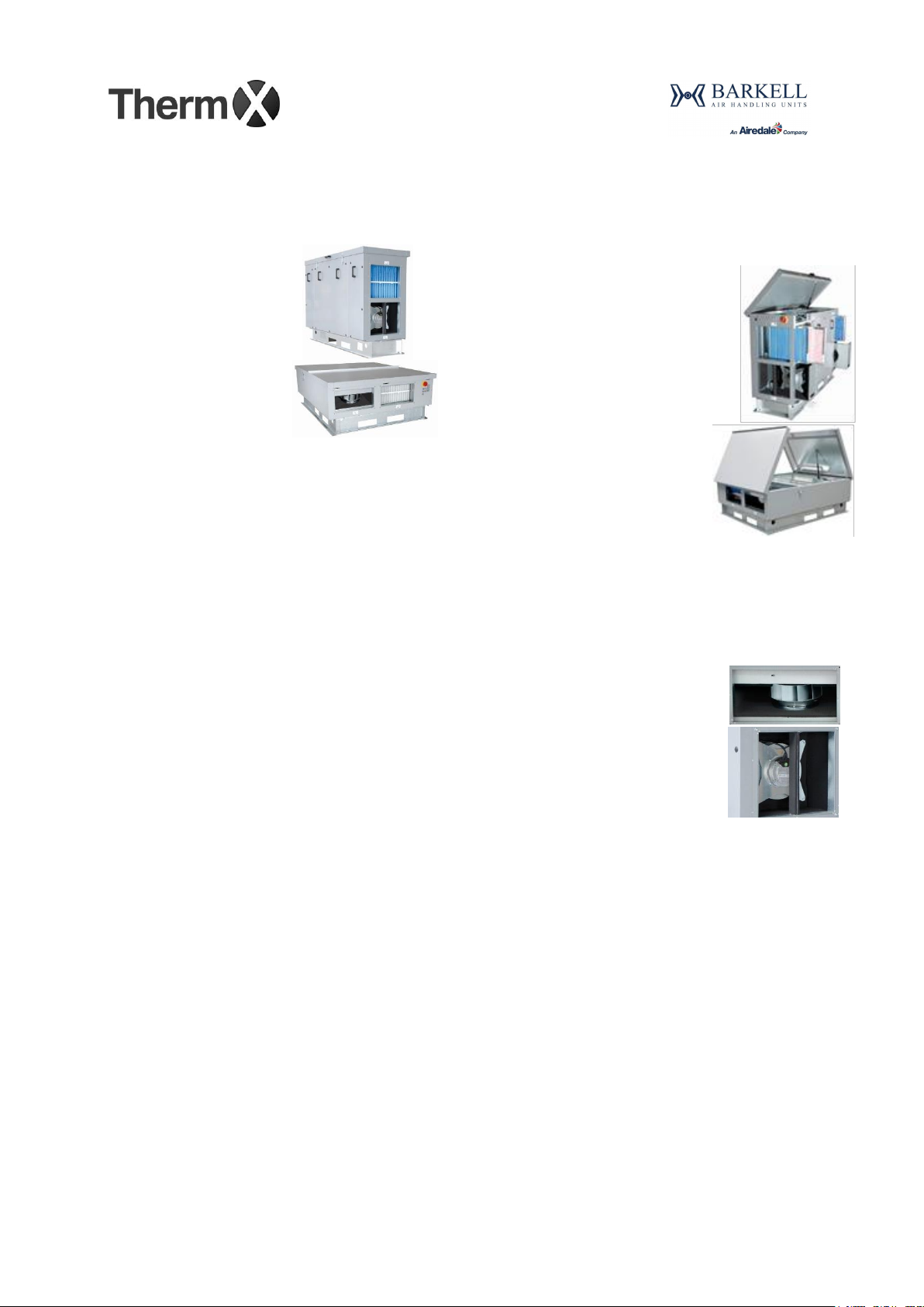
The filters are mounted on slides for easy removal
and tightly sealed against the slide rails to ensure
reduced filter bypass leakage.
2.6. COUNTER FLOW PLATE HEAT
EXCHANGER
The heat recovery section is equipped with a highly
efficient counter-flow air to air heat exchanger,
exceeding the 2018 requirements of regulation
1253/2014 of the Eco-design directive for ventilation
units, with operational efficiency up to 93%.
The heat exchanger finned block
and casing are manufactured
from high thermal
transmittance and corrosion
resistant aluminium.
The exchanger is Eurovent certified and fully
tested to EN308:1997.
The heat recovery section is also provided with fully
modulating face and by-pass damper to provide
close control of the supply air temperature and
enable free cooling operation when the conditions
are favourable (e.g. summer night ventilation).
In extreme conditions when the exhaust temperature
drops below the frost risk limit the unit controls
strategy provides frost protection for the heat
exchanger by bypassing some of the cold air.
Where it’s not desirable to impact the unit operation
during the frost protection strategy, an electric pre-
heating coil (frost coil) can be offered to provide
improved frost protection.
A fully removable, epoxy coated, galvanized steel
condensate tray fitted with an thermally insulated
condensate trap (located on the base frame of the
unit) and a 40mm OD drain
connection is provided for
condensate collection and
disposal.
The condensate tray is
equipped with a water level sensor to avoid
overflow of the tray by stopping operation.
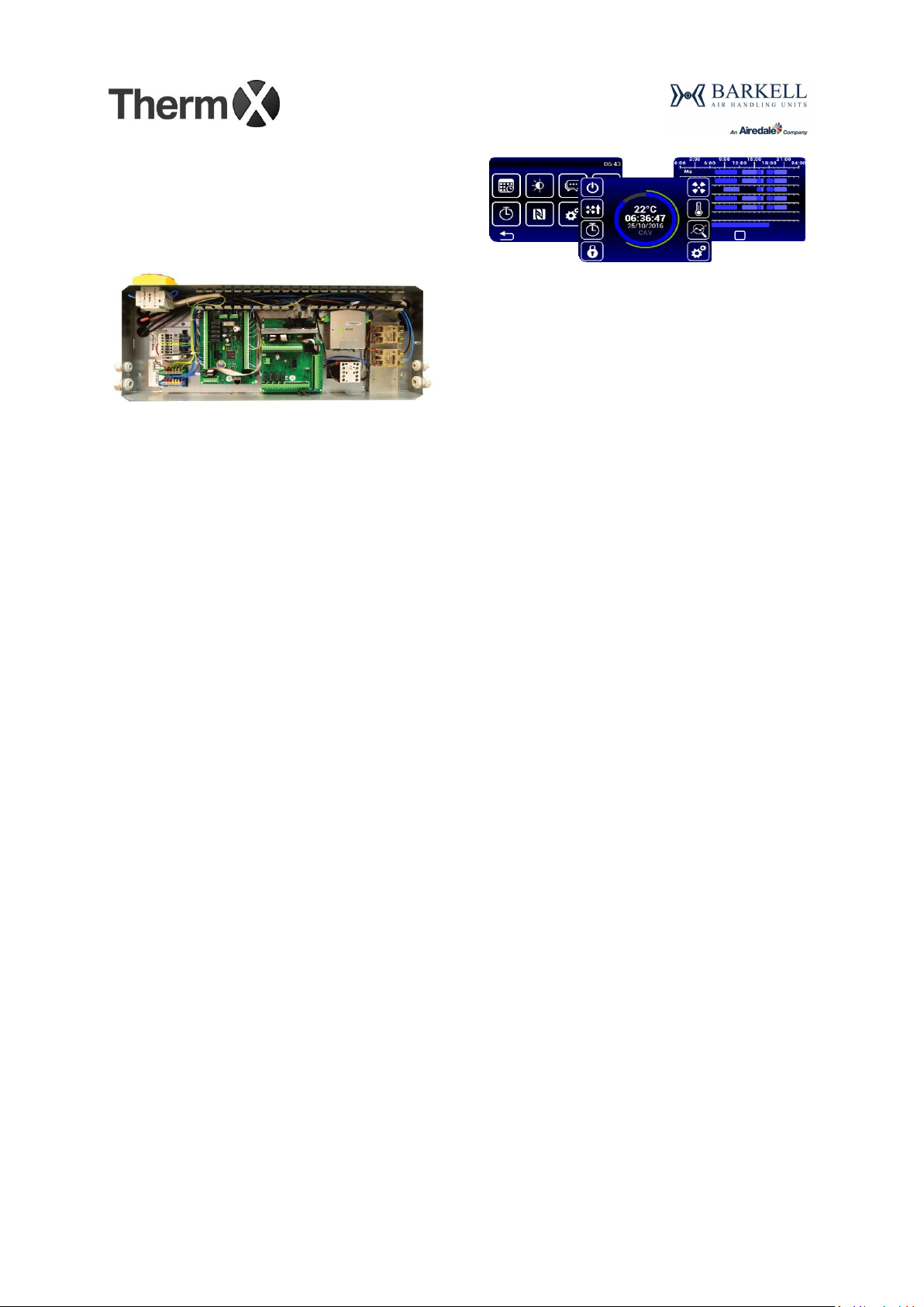
2.7. OPTIONAL FEATURES
2.7.1. INTEGRAL ELECTRICAL PRE/POST-
HEATING COIL
The unit can optionally be fitted with an electrical
pre-heater and/or post-heater manufactured with
open coil heating elements and galvanized casing.
The heater is complete with fully modulating SCR
(Silicon Controlled Rectifier) control (0-10V) and
2 stages of overheat protection (automatic and
manual reset) all integral to the unit’s control strategy.
The SCR control provides accurate, supply air
temperature modulation.
The heat output is precisely controlled from 0 to 100%
to a user defined setpoint by using the unit in-built
temperature sensors or a room temperature
sensor (supplied with every unit, installation and
wiring on site by others).
The electric pre-heating coil is recommended where
sub-zero temperatures are expected.
The electrical post-heating coil is recommended
where no hot water supply is available on site and
there is need for top-up heating of the supply air.

Therm-X MVHRU HR95
Technical Manual
Page 6 of 59
Version 2.4, 25/09/2020
2.7.2. INTEGRAL LPHW POST HEATING COIL
The unit can optionally be supplied with an
integral water heater operating with LPHW to
provide supply air top up heating.
The coils are manufactured with aluminium fins,
copper tubes and assembled on a corrosion
resistant galvanized casing.
The maximum operating pressure is 16bar at 110°C.
The heating output is automatically modulated by the
in-built temperature sensors and the integral unit
controls.
Valves and actuators are not included and must be
ordered separately
2.7.3. INTEGRAL DX (DIRECT EXPANSION)
OR WCO (WATER CHANGEOVER COIL)
Where cooling is also required an optional
changeover water coil can be provided operating
with either chilled and/or hot water (depending on the
seasonal requirements) on a common water circuit.
Alternatively a single circuit reverse cycle direct
expansion (DX) coil operating with R410A
refrigerant can be offered.
All DX coils are tested to 46bar.
Both DX and WCO coils are manufactured with
aluminium fins with hydrophilic coating, copper
tubes and assembled on a corrosion resistant
galvanized casing. The cooling coil section is also
equipped with a plastic droplet eliminator.
A fully removable, epoxy coated, galvanized
condensate tray fitted with a 22mm OD drain
connection is provided for condensate collection and
disposal.
The condensate tray is equipped with a water level
sensor to avoid overflow of the tray by stopping
operation.
2.7.4. ACCESSORIES
All Therm-X units have available a wide range of
mechanical and control accessories compatible with
the units to facilitate installation and enhance the
unit’s operation.
The accessories available for the HR95 range:
Motorized shut off dampers
Backdraft dampers
Square to round transitions
Spare filters
Duct mounted electrical heaters
Duct mounted LPHW heaters
Duct mounted circular attenuators
Matched rectangular attenuators (straight and
bend)
Condensate pump kit
Condensate trap
Duct and room mounted IAQ sensors (CO2,
humidity)
PIR motion sensor
Valve kits
Matched refrigeration systems

Therm-X MVHRU HR95
Technical Manual
Page 7 of 59
Version 2.4, 25/09/2020
2.8. TESTING
All unit models undergo a stringent set of tests to the
relevant European standards in an accredited
laboratory to ensure accurate catalogue data.
Performance is tested to ISO 5801:2007 Industrial
fans –performance testing using standardized
airways.
Casing radiated noise acoustically tested to BS
EN 3744:2010 –Acoustics - Determination of sound
power levels and sound energy levels of noise
sources using sound pressure - Engineering
methods for an essentially free field over a reflecting
plane.
Published figures are for a non-punctiform source
and spherical propagation as described in ISO
3744.
In duct noise acoustically tested to BS EN ISO
5136:2010 - Acoustics –Determination of sound
power radiated into a duct by fans and other air-
moving devices - In-duct method.
Heat recovery efficiency tested to EN 308:1997 -
Heat exchangers - Test procedures for establishing
performance of air to air and flue gases heat
recovery devices.
Model box casing performance tested to
EN1886:2007 - Ventilation for buildings - Air
handling units:
Thermal transmittance of the casing - T3 (MB)
Thermal bridging of the casing - TB4 (MB)
Casing air leakage - L1 (MB)
Casing strength –D2 (MB)
Testing tolerances in accordance with
COMMISSION REGULATION (EU) No 1253/2014
are as follows:
SFPint –Declared value x 1.07
Thermal Efficiency –Declared value x 0.93
Sound power level –Declared value + 5dB
2.9. BUILDING REGULATIONS AND ECO-
DESIGN DIRECTIVE
All models are performance tested and
measurements are made to obtain the power
consumption of the units at several operating points.
These tests were conducted to evaluate the
performance of the unit at standard configuration
(G4+F7/G4) and as per the ErP directive (F7/M5
filters).
The units are able to operate within the limits of both
of these regulations under most conditions. To
provide accurate performance data a detailed
software selection can be produced.

Therm-X MVHRU HR95
Technical Manual
Page 8 of 59
Version 2.4, 25/09/2020
2.10. CONTROLS
All Therm-X MVHR units are factory fitted with a
Plug&Play fully integral intelligent control
package.
The factory fitted controls include:
Sealed controls enclosure with unit PCB and all
electrics
Mains switch isolator
Face and bypass damper actuator
4 temperature sensors (fresh air, supply air (x2),
return air)
1 sensor for antifreeze protection (exhaust air)
2 digital pressure sensors for filters
3 digital pressure sensors for airflow
measurement and constant pressure operation
2 water temperature sensors (only versions with
water or direct expansion coils)
1 condensate level sensor (x2 for versions with
cooling coil option)
Automatic and manual thermal reset for electric
heaters (only versions with electric heaters)
All units are also provided with the following loose
items (installation and wiring by others):
1 room temperature sensor
1 handheld touchscreen controller (wiring on
site by others, cable not supplied, CAT5 UTP
cable recommended as minimum)
The in-built controls are pre-configured and offer
several alternatives to operate your Therm-X unit.
The controls are ready to go from the moment
the unit is turned ON, and can be easily configured
with the help of the handheld controller provided
(excludes externally mounted sensors which are
supplied loose and require installation and wiring by
others on site).
Some of the features offered by the controller are
listed below:
2.10.1.AIRFLOW CONTROL
The controls offer continuous modulation of the
airflow range of the unit in 10% steps.
The ratio of airflows for supply and exhaust can be
adjusted according to the requirements of the project
(+-50%).
The unit can be set to operate in distinct ventilation
modes to control the supply of outside air for
ventilation purposes.
CAV (Constant Air Volume) mode
The unit is programmed to supply a constant amount
of air to the ventilated space.
The unit will adjust the output of the fans according
to the internal or external pressure changes in order
to maintain the amount of air being supplied to the
rooms constant.
VAV (Variable Air Volume) mode
The unit is programmed to adjust the fans output to
maintain a constant pressure in the supply duct while
varying the air volume according to the demand of
the ventilated space.
The unit adjusts the supply flow rate according to the
overall opening of the supply VAV terminal units in
the ductwork system.

Therm-X MVHRU HR95
Technical Manual
Page 9 of 59
Version 2.4, 25/09/2020
DCV (Demand Controlled Ventilation) mode
The unit is programmed to adjust the supply airflow
according to the occupancy on the ventilated space
matching the outdoor air supply to the ventilation
demand.
The fan output is determined by a 0-10V input from
an air quality sensor (CO2, RH, VOC, etc.., can be
ordered from Barkell, installation and wiring on site
by others).
The flow rate is controlled according to the 0-10V
signal.
“Breathing”
The unit can be set to turn OFF when the IAQ
requirements on the ventilated space are satisfied in
order to save energy.
The unit then turns ON regularly to “breathe” and
check the concentration of pollutants, returning to
normal operation if required.
Trickle mode
If a PIR motion sensor is installed in the ventilated
space (can be ordered from Barkell, installation and
wiring by others), in the event of no occupancy the
unit provides only minimum background ventilation
to save energy.
Boost mode
When there is a high demand for ventilation or swift
heating or cooling of the space is necessary (e.g. unit
start up) the boost mode overrides the operation of
the unit and runs the fans at the maximum defined
airflow for the time period determined by the user.
The boost mode can be enabled with the supplied
handheld controller or an external switch (by others).
Time scheduling
The unit can be set to operate on a timed operation
on weekly and/or yearly schedules with individual
settings for up to six time blocks per day/year.
2.10.2.TEMPERATURE CONTROL
The unit is able to control the conditioned space
temperature based on the temperature of the supply
or return air.
Temperature control based on room temperature is
also possible given the room temperature sensor
(supplied with every unit) is installed (on site by
others).
The unit automatically and continuously controls the
output of the heat recovery device and the optional
integral and external heat exchangers (if installed) in
order to achieve the set-point temperature defined by
the user.
The supply air temperature is kept in between the
limits defined during commissioning to avoid very
cold or very hot air being supplied to the room.
Automatic free cooling
The unit automatically detects favourable conditions
for free-cooling and ventilates using the cold outside
air to achieve space cooling savings.

Therm-X MVHRU HR95
Technical Manual
Page 10 of 59
Version 2.4, 25/09/2020
2.10.3.OTHER CONTROL FEATURES
In addition to the basic ventilation and temperature
control the Therm-X controller offers a range of
features to extend the functionality, facilitate
commissioning operation and maintenance of the
equipment.
Safety
FIRE MODE interlock with BMS
Soft start up
Frost protection of the heat exchangers
Overheat protection of the electric heaters
Condensate tray overflow protection
Fault and emergency alarms on the handheld
controller
Memory of last operational state in event of
power outage
Commissioning
Automatic calibration of filters and fans during
commissioning
Component test mode
PID tuning
Maintenance
Continuous monitoring of the filter status
Dirty filter alarm
External control
External enable/disable, error and run
signalisation relay contacts
Control of external heat pump via ON/OFF or
proportional 0-10V enable, error and defrost
signal
Control of up to two external shut-off dampers
(can be ordered from Barkell, installation and
wiring by others on site)
Control of 2nd external pre-heating coil –water
or electric (can be ordered from Barkell,
installation and wiring by others on site)
Control of 2nd external post-heating coil –
water, electric or direct expansion (can be
ordered from Barkell, installation and wiring by
others on site)
For further information about the external control
functions of the Therm-X controls please contact our
offices.
2.10.4.COMMUNICATION
The unit can be set-up and controlled via the
handheld touchscreen controller supplied or via the
BMS.
Handheld Controller
The handheld control panel is
a powerful tool for setting up
and operating the Therm-X
units.
End user level functions:
Adjusting operational parameters –set point
temperature, airflow
Activate BOOST MODE
Set TIME SCHEDULING
Display alarms and faults in detail
Monitor the unit operation
Near Field Communication (NFC)
Commissioning level functions:
Full set-up and calibration of the unit
Select and set up ventilation modes
Set-up secondary ventilation modes –BOOST,
TRICKLE, FREECOOLING
Set airflow offset, temperature limits, etc..
Test individual components
Set end-user level access protection
The hand-held controller has a fully touchscreen
based interface with full RGB colour scheme and
supports NFC communication.
The controller must be wired to the unit with a
suitable communication cable (not supplied by
Barkell, UTP CAT5 cable as minimum, by others on
site) not exceeding a length of 50m.
BMS integration
BMS integration is provided by connecting the unit
control panel through a BacNet TCP/IP, MODBUS
RTU (RS485) and MODBUS TCP/IP protocol
allowing full control and monitoring of the unit.
Other protocols can be enabled with the use of an
gateway converter (not sold by Barkell, must be
programmed by a BMS or controls specialist).

Therm-X MVHRU HR95
Technical Manual
Page 11 of 59
Version 2.4, 25/09/2020
2.10.5.CONTROLS SET-UP
The set-up of the controls on the Therm-X unit can
be performed by one of our experienced
commissioning teams.
We offer the following options to perform the
commissioning of your Therm-X units:
Site attendance for demonstration of controls
set-up
With this option one of our experienced engineers
will attend to site for one day and demonstrate how
to calibrate and set the controls for one Therm-X unit.
Site attendance for controls set-up
With this option one of our experienced engineers
will attend to site to check the installation and wiring
of every unit as well as calibrate and set up the
controls to the required project design conditions.
For additional information about our commissioning
options please contact our offices.
Please note:
Any mechanical or electrical works must be
completed before our engineers attend to site to
set-up the controls
Barkell will not perform the integration of the
units to the BMS
Demonstration of specific controls functionality
and witnessing is not included and must be
requested separately
2.11. SERVICE SOFTWARE
The Therm-X service software allows full control of
the equipment and easy commissioning with a user-
friendly interface.
The software can also be used to easily transfer
settings between units making the commissioning of
large identical installations much swifter.
2.12. WARRANTY
All units are provided with 36 months warranty
starting from the date of delivery.
The warranty covers replacement parts only.

Therm-X MVHRU HR95
Technical Manual
Page 12 of 59
Version 2.4, 25/09/2020
3. OPERATIONAL DIAGRAM
Horizontal (side by side) Configuration
PLAN VIEW (TOP)
Vertical (double deck) Configuration
ELEVATION VIEW (ACCESS SIDE)
1
EC plenum fan
2
PHE with bypass damper
3
Panel filter - supply G4+F7, return G4
4
Control panel
5
Condensate collection and disposal (integral trap)
6
Optional post-heating coil –Electric, LPHW, WCO or DX
7
Bypass damper
8
Optional electric pre-heating coil
Key:
OTA - Outside air
SUP - Supply air
ETA - Extract air
EHA - Exhaust air

Therm-X MVHRU HR95
Technical Manual
Page 13 of 59
Version 2.4, 25/09/2020
4. AIRFLOW PERFORMANCE
Airflow performance as tested to ISO 5801:2007, Installation category D:
HR95-080-V (Vertical)
HR95-080-H (Horizontal)
PLEASE NOTE:
-Performance is shown for standard configuration with F7 supply and M5 extract filters, clean filters, SPI is for
both fans
-For accurate performance data please request a detailed software selection

Therm-X MVHRU HR95
Technical Manual
Page 14 of 59
Version 2.4, 25/09/2020
Airflow performance as tested to ISO 5801:2007, Installation category D:
HR95-150-V (Vertical)
HR95-150-H (Horizontal)
PLEASE NOTE:
-Performance is shown for standard configuration with F7 supply and M5 extract filters, clean filters, SPI is for
both fans
-For accurate performance data please request a detailed software selection

Therm-X MVHRU HR95
Technical Manual
Page 15 of 59
Version 2.4, 25/09/2020
Airflow performance as tested to ISO 5801:2007, Installation category D:
HR95-250-V (Vertical)
HR95-250-H (Horizontal)
PLEASE NOTE:
-Performance is shown for standard configuration with F7 supply and M5 extract filters, clean filters, SPI is for
both fans
-For accurate performance data please request a detailed software selection

Therm-X MVHRU HR95
Technical Manual
Page 16 of 59
Version 2.4, 25/09/2020
Airflow performance as tested to ISO 5801:2007, Installation category D:
HR95-350-V (Vertical)
HR95-350-H (Horizontal)
PLEASE NOTE:
-Performance is shown for standard configuration with F7 supply and M5 extract filters, clean filters, SPI is for
both fans
-For accurate performance data please request a detailed software selection

Therm-X MVHRU HR95
Technical Manual
Page 17 of 59
Version 2.4, 25/09/2020
Airflow performance as tested to ISO 5801:2007, Installation category D:
HR95-450-V (Vertical)
HR95-550-V (Vertical)
PLEASE NOTE:
-Performance is shown for standard configuration with F7 supply and M5 extract filters, clean filters, SPI is for
both fans
-For accurate performance data please request a detailed software selection

Therm-X MVHRU HR95
Technical Manual
Page 18 of 59
Version 2.4, 25/09/2020
5. HEAT RECOVERY PERFORMANCE
Heat recovery efficiency as tested to EN 308:1997:
HR95-V
PLEASE NOTE:
-Heat recovery efficiency is measured under the following conditions:
-Outdoor air conditions: -5°C / 90%
-Indoor air conditions: 20°C / 65%
-Efficiencies stated are for dry conditions
-For accurate heat recovery performance data please request a detailed software selection

Therm-X MVHRU HR95
Technical Manual
Page 19 of 59
Version 2.4, 25/09/2020
Heat recovery efficiency as tested to EN 308:1997:
HR95-H
PLEASE NOTE:
-Heat recovery efficiency is measured under the following conditions:
-Outdoor air conditions: -5°C / 90%
-Indoor air conditions: 20°C / 65%
-Efficiencies stated are for dry conditions
-For accurate heat recovery performance data please request a detailed software selection

Therm-X MVHRU HR95
Technical Manual
Page 20 of 59
Version 2.4, 25/09/2020
6. ACOUSTIC PERFORMANCE
HR95-080-H
Air Volume
[m3.h-1]
Air Volume
[m3.s-1]
ESP
[Pa]
SFP
[W.(l.s)-1]
Casing Breakout @ 3m
[dB(A)]
375
0.10
200
1.90
34
281
0.08
200
1.79
31
188
0.05
200
1.84
28
500
0.14
150
1.89
37
375
0.10
150
1.60
32
250
0.07
150
1.46
27
590
0.16
100
1.89
38
443
0.12
100
1.46
32
295
0.08
100
1.18
25
665
0.18
50
1.88
39
499
0.14
50
1.32
32
333
0.09
50
0.94
23
HR95-150-H
Air Volume
[m3.h-1]
Air Volume
[m3.s-1]
ESP
[Pa]
SFP
[W.(l.s)-1]
Casing Breakout @ 3m
[dB(A)]
1110
0.31
200
1.90
37
833
0.23
200
1.59
33
555
0.15
200
1.48
31
1240
0.34
150
1.90
39
930
0.26
150
1.46
33
620
0.17
150
1.23
31
1350
0.38
100
1.90
41
1013
0.28
100
1.34
33
675
0.19
100
1.02
29
1440
0.40
50
1.89
43
1080
0.30
50
1.24
33
720
0.20
50
0.82
28
PLEASE NOTE:
-Performance is shown for standard configuration with G4+F7 supply and G4 extract filters, midpoint filters
-Casing breakout at 3 meters calculated for a non-punctiform source and spherical propagation as described
in ISO 3744
-For accurate acoustic performance data please request a detailed software selection
This manual suits for next models
10
Table of contents
Other AIREDALE Fan manuals
Popular Fan manuals by other brands

Hunter
Hunter Alexander 51939 installation manual

Vortice
Vortice C ATEX Instruction booklet

Envirovent
Envirovent filterless extractor fan installation guide

Soleus Air
Soleus Air FC1-15-30 owner's manual

Gulf Coast Fans
Gulf Coast Fans Twin Star III owner's manual

GoWISE USA
GoWISE USA Ultra Air 42" GW21102 user guide