AIREDALE Barkell Therm X HRFL II User manual

MECHANICAL VENTILATION AND HEAT
RECOVERY UNITS
HRFL II | HR85 | HR95
INSTALLATION, OPERATION AND MAINTENANCE
MANUAL
Version 2.2, 18/06/2020

CONTENTS
INTRODUCTION 3
DELIVERY 4
UNPACKING THE GOODS 5
HANDLING THE GOODS 6
STORAGE 7
PRODUCT OVERVIEW 8
TECHNICAL DATA 15
DIMENSIONS AND WEIGHTS 22
CODING KEY 49
INSTALLATION 52
ELECTRICAL INSTALLATION 68
INSTALLATION OF ACCESSORIES 78
FIRST USE 90
MAINTENANCE 91
TROUBLESHOOTING 95
SPARES 104
DISPOSAL 107
CONCLUSION 107

THERM-X MVHRU IOM
Page 3 of 108
Version 2.2, 18/06/2020
1. INTRODUCTION
This manual contains important instructions for the safe installation of the ventilation unit. Before proceeding with
the installation of the unit please read the instructions in this manual attentively.
The manufacturer reserves the right to make changes to the technical documentation without prior notice. Please
store this manual for future use. This manual is a part of the product.
EC CONFORMITY DECLARATION
The product has been designed, manufactured and placed on the market in compliance with all the requirements
of the directives of the European Parliament and the Council, including amendments to the proposal under which
it was classified.
When handled/operated under normal conditions and in accordance with the IOM manual, the installation,
operation and maintenance of this product is safe. The harmonized European standards referred to in the relevant
EC declaration of conformity have been applied in the assessment.
For the current and full version of the EC Declaration of Conformity, please refer to the document package provided
at the time of order confirmation.

THERM-X MVHRU IOM
Page 4 of 108
Version 2.2, 18/06/2020
2. DELIVERY
2.1. CHECKING THE GOODS
All products are inspected prior to leaving the factory.
Immediately after receiving the goods make a visual inspection of the packages. In case of visible packaging
damage note the damage in the delivery note provided by the delivery driver and inform Barkell immediately.
Barkell will not accept claims for damage sustained during or after offloading and positioning the product on
site.
Check whether the delivered type and quantity of the products matches the order. Ensure that any ordered
ancillary items (sensors, dampers, duct heaters, etc..) are included with the delivery. In case of shortage inform
Barkell immediately.
All claims for damage or missing goods must be reported to Barkell immediately and confirmed in writing within
2 working days upon receipt of the goods otherwise the right to claim will be lost.
If the product is not unpacked immediately after delivery it must be stored in a dry internal location with an
ambient temperature between +5°C and +35°C.
PLEASE NOTE: Ancillaries are normally packaged together with the product or stored inside of the product
itself.
Large items such as attenuators, duct transitions or duct heat exchangers are supplied on a separate pallet.

THERM-X MVHRU IOM
Page 5 of 108
Version 2.2, 18/06/2020
2.2. UNPACKING THE GOODS
The method of packing is for products to be loaded onto crates or pallets and secured with bolts. A protective
film is added to minimize any potential water and dust ingress.
If the product is not delivered in a pallet the integral base frame of the equipment should be used for handling.
Ensure any safety bolts are unfastened before attempting to remove the equipment from the pallet otherwise
permanent damage might occur.
If the equipment was transported at temperatures below 0°C it is recommended to leave it in the operating
environment for at least 2 hours after unpacking for temperature compensation to take place.
After unpacking the equipment check whether the unit and other parts have been supplied in good condition.
All claims for damage or missing goods must be reported to Barkell immediately and confirmed in writing within
2 working days upon receipt of the goods otherwise the right to claim will be lost.
IMPORTANT: Never attempt to put a damaged ventilation unit into operation.
IMPORTANT: Small items such as controllers and sensors are packaged either together with the product
packaging or inside the product.
Do not dispose of the packaging before verifying all items have been removed from it.
Do not put the product into operation before verifying there are no loose items inside it.

THERM-X MVHRU IOM
Page 6 of 108
Version 2.2, 18/06/2020
Every Therm-X product is delivered with:
1 x Touchscreen Controller (CP-TC-XX-01-0)
1 x Room Temperature Sensor (CT-ROOM)
Additionally, all Therm-X HR85 products are also delivered with:
1 x Mains circuit breaker 1.5 m cable
(except for HR85-070 size that has a supply cable of CEE 7/16 “Europlug“ type)
HR85-070 products delivered with a duct LPHW, WCO or DX coil are also delivered with:
•3 x 10m long probe temperature sensor type NTC R25=10 kOhm,+-5%,B25/100=3950K+-1 (ND-
CT-NTC-10-UL)
PLEASE NOTE: Controller supplied loose for installation and wiring on site by others.
Cabling not included. CAT5 unshielded twisted pair cable is recommended as minimum. Cable length
should not exceed 50 meters (0.5 mm2) to avoid loss of communication.
The controller is not suitable for external installation.
PLEASE NOTE: Sensor supplied loose for installation and wiring on site by others.
Cabling not included. The sensor is not suitable for external installation.
IMPORTANT: In addition to the items listed above there might also be other small items such as fasteners,
gaskets or sealant provided to facilitate the installation of the product.
These loose items will either be packaged together with the product or inside the product.
Do not dispose of the packaging before ensuring all items have been removed.
Do not put the product into operation before ensuring all items have been removed from the inside.

THERM-X MVHRU IOM
Page 7 of 108
Version 2.2, 18/06/2020
2.3. HANDLING THE GOODS
Before off-loading the goods please ensure that a suitable means of transport/lifting to accommodate the
weight and size of the equipment is available.
The weight of the equipment is displayed on the manufacturing label fitted on the outside of the packaging, on
the equipment control panel door and on the documentation provided at the time of order confirmation. Please
check the weight of the unit before attempting to handle it.
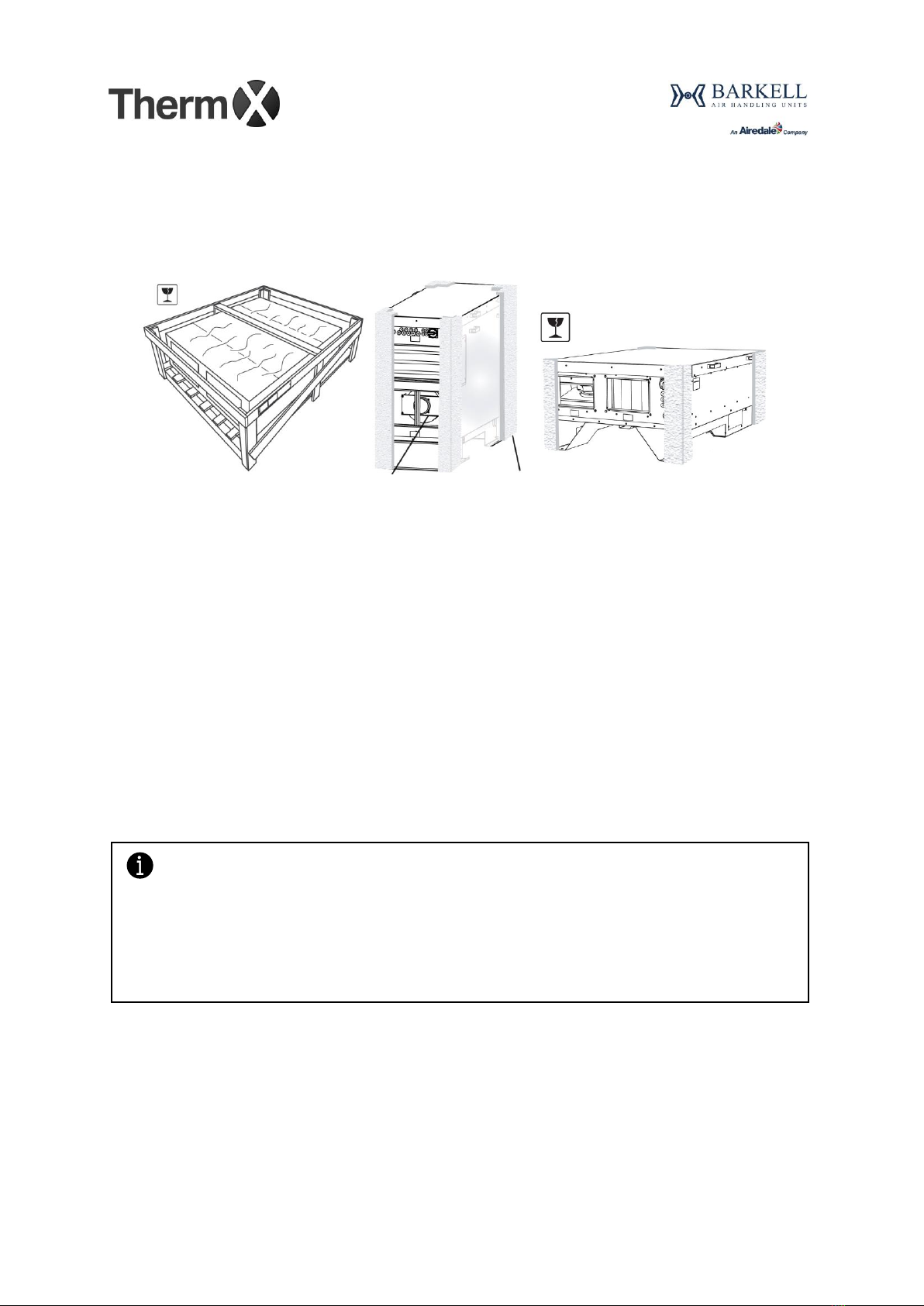
For products delivered in pallets or with integral base frame the use of a fork-lift or pallet truck is recommended.
If the equipment needs to be lifted with straps it is recommended to use spreaders to avoid damage to the
casing.
Manual lifting between floor and shoulder level is acceptable only up to a maximum weight of 20kg
(89/391/CEE).
Take care when handling the equipment to ensure that damage to coil pipe work connections, spigots, drain
trays, etc. is avoided.
3. STORAGE
Should it be required to store the products on site for any period of time prior to installation they should be
stored in a clean, dry and secure area with an ambient temperature between 5°C and 35°C.
Inlet and discharge openings, pipe connections and filters should be sealed to avoid moisture ingress.
The equipment should be inspected on a regular basis and its packaging repaired if damaged.
The equipment should not be stored in areas where there is excessive vibration as this could damage fan
motor bearings.
If access panels are removed for inspection purposes or to carry out work on site they should be refitted and
made secure.
Small items delivered with the equipment such as sensors, controllers, etc… shall be stored safely from
unauthorized access, damage and the weather.
Crated or palletized horizontal mounting ceiling products (HRFL2) can be stacked on top of each other for
transport up to a maximum of 2 units high. For long term storage the maximum allowable stacking will depend
on the size of the unit, please contact our offices for more information.
Free standing units (HR85, HR95) cannot be stacked.

THERM-X MVHRU IOM
Page 8 of 108
Version 2.2, 18/06/2020
4. PRODUCT OVERVIEW
HRFL2 (Ceiling Void MVHR with Plate Heat Exchanger)
PLEASE NOTE: All HRFL II ceiling mounted units are supplied with F7 and M5 filters as standard.
If a different filter grade is selected the filter is supplied loose for replacement on site by others (controls
system filter calibration is required).
PLEASE NOTE: All HRFL II units are supplied in a single piece.
Optional external modules with cooling coils are supplied loose for installation and wiring on site by others.
HRFLII unit modules with a cooling coil (either DX or WCO) have an additional condensate drain
connection that must be trapped and connected to a suitable wastewater discharge separately.

THERM-X MVHRU IOM
Page 9 of 108
Version 2.2, 18/06/2020
HRFL2 (Ceiling Void MVHR with Plate Heat Exchanger)
PLAN VIEW (BOTTOM)
Key:
OTA - Outside air
SUP - Supply air
ETA - Extract air
EHA - Exhaust air
*External cooling modules with DX and WCO coils are also available (supplied loose, installation and wiring on site by others)
**Optional F9 supply filter available
1
EC plenum fan
2
Panel filter - supply F7**, return M5
3
Optional electric pre-heating coil
4
Optional post-heating coil - Electric or LPHW*
5
Condensate collection and disposal
6
PHE with bypass damper

THERM-X MVHRU IOM
Page 10 of 108
Version 2.2, 18/06/2020
HR95-V (Free Standing Vertical MVHR with Plate Heat Exchanger)
INTEGRAL DRAIN TRAP (PHE CONDENSATE) COIL CONDENSATE CONNECTION
PLEASE NOTE: HR95 units with a cooling coil (either DX or WCO) have an additional condensate drain
connection that must be trapped and connected to a suitable wastewater discharge separately.
.
PLEASE NOTE: HR95 units are supplied in a single piece and are equipped with and integral base frame.
The base frame is not removable.

THERM-X MVHRU IOM
Page 11 of 108
Version 2.2, 18/06/2020
HR95-H (Free Standing Horizontal MVHR with Plate Heat Exchanger)
INTEGRAL DRAIN TRAP
PLEASE NOTE: HR95 units with a cooling coil (either DX or WCO) have an additional condensate drain
connection that must be trapped and connected to a suitable wastewater discharge separately.
.
PLEASE NOTE: HR95 units are supplied in a single piece and are equipped with and integral base frame. The
base frame is not removable.

THERM-X MVHRU IOM
Page 12 of 108
Version 2.2, 18/06/2020
HR95 (Free Standing MVHR with Plate Heat Exchanger)
Horizontal (side by side) Configuration
PLAN VIEW (TOP)
Vertical (double deck) Configuration
ELEVATION VIEW (ACCESS SIDE)
1
EC plenum fan
2
PHE with bypass damper
3
Panel filter - supply G4+F7, return G4
4
Control panel
5
Condensate collection and disposal (integral trap)
6
Optional post-heating coil –Electric, LPHW, WCO or DX
7
Bypass damper
8
Optional electric pre-heating coil
Key:
OTA - Outside air
SUP - Supply air
ETA- Extract air
EHA - Exhaust air

THERM-X MVHRU IOM
Page 13 of 108
Version 2.2, 18/06/2020
HR85 (Free Standing MVHR with Rotary Heat Exchanger)
PLEASE NOTE: HR85 units with a cooling coil (either DX or WCO) have an additional condensate drain
connection that must be trapped and connected to a suitable wastewater discharge separately.
.
PLEASE NOTE: All HR85 units are supplied with M5 filters as standard.
If a different filter grade is selected the filter is supplied loose for replacement on site by others (controls
system filter calibration is required).
PLEASE NOTE: For HR85-070 units with DX, WCO or LPHW coils the coil is supplied loose for duct
mounting and wiring by others.
HR85 units up to size 200 are supplied in a single piece with integral base frame. The base frame is not
removable.
Larger units (size 300 and larger) are supplied in a modular arrangement with each section individually
packed and provided with quick-fit electrical and mechanical connections (assembly and wiring on site by
others). Each section is provided with individual integral base frames. The base frame is not removable.

THERM-X MVHRU IOM
Page 14 of 108
Version 2.2, 18/06/2020
HR85 (Free Standing MVHR with Rotary Heat Exchanger)
Upper Configuration (top connections)
ELEVATION VIEW (ACCESS SIDE)
Vertical Configuration (Side Connections)
ELEVATION VIEW (ACCESS SIDE
Key:
OTA - Outside air
SUP - Supply air
ETA - Extract air
EHA - Exhaust air
(1) For unit size 070 the coil is supplied loose for fitting and wiring by others on site (including duct air temperature and coil
water temperature sensors). It is not required to order the coil separately.
(2) Optional supply F7 filter available on request
PLEASE NOTE:
−The internal configuration might vary depending on the size of the unit
1
EC plenum fan
2
Rotary heat exchanger (condensation)
3
Panel/Bag filter - M5 (2)
4
Optional post-heating coil –Electric, LPHW, WCO or DX (1)
5
Condensate collection and disposal (for cooling coils)

THERM-X MVHRU IOM
Page 15 of 108
Version 2.2, 18/06/2020
5. TECHNICAL DATA
5.1. ELECTRICAL CHARACTERISTICS
HRFL2 (Ceiling Void MVHR with Plate Heat Exchanger)
Models without electric pre-heating coil and… without coil / with water heating coil / with WCO coil / with
DX coil
Unit
Type
Phase
Voltage
[V]
Frequency
[Hz]
Power Input
[kW]
Full load current
per phase [A]
HRFL2-040
1
230 V
50 Hz
0.23
2.2
HRFL2 070
1
230 V
50 Hz
0.33
2.5
HRFL2-150
1
230 V
50 Hz
1.10
6.8
HRFL2-200
1
230 V
50 Hz
1.10
6.3
Models without electric pre-heating coil and… with electric post heating coil
Unit
Type
Phase
Voltage
[V]
Frequency
[Hz]
Power Input
[kW]
Full load current
per phase [A]
HRFL2-040
1
230 V
50 Hz
1.10
5.7
HRFL2-070
1
230 V
50 Hz
1.80
8.6
HRFL2-150
1
230 V
50 Hz
3.80
18.5
HRFL2-200
3
400 V
50 Hz
5.90
12.3
Model with electric pre-heating coil and… without coil / with water heating coil / with WCO coil / with DX
coil
Unit
Type
Phase
Voltage
[V]
Frequency
[Hz]
Power Input
[kW]
Full load current
per phase [A]
HRFL2-040
1
230 V
50 Hz
1.70
8.3
HRFL2-070
1
230 V
50 Hz
3.10
14.3
HRFL2-150
3
400 V
50 Hz
6.40
13.3
HRFL2-200
3
400 V
50 Hz
8.30
16.7
Model with electric pre-heating coil and with electric post heating coil
Unit
Type
Phase
Voltage
[V]
Frequency
[Hz]
Power Input
[kW]
Full load current
per phase [A]
HRFL2-040
1
230 V
50 Hz
2.50
11.8
HRFL2-070
3
400 V
50 Hz
4.50
11.8
HRFL2-150
3
400 V
50 Hz
9.10
18.5
HRFL2-200
3
400 V
50 Hz
13.10
22.5

THERM-X MVHRU IOM
Page 16 of 108
Version 2.2, 18/06/2020
HRFL2 (Ceiling Void MVHR with Plate Heat Exchanger)
Fan electric motor (per fan)
Electric post heating coil
Unit
Type
Phase
Voltage
[V]
Frequency
[Hz]
Power Input [kW]
HRFL2-040
1
230 V
50 Hz
0.80
HRFL2-070
1
230 V
50 Hz
1.40
HRFL2-150
1
230 V
50 Hz
2.70
HRFL2-200
3
400 V
50 Hz
4.80
Electric pre heating coil
Unit
Type
Phase
Voltage
[V]
Frequency
[Hz]
Power Input [kW]
HRFL2-040
1
230 V
50 Hz
1.40
HRFL2-070
1
230 V
50 Hz
2.70
HRFL2-150
3
400 V
50 Hz
5.30
HRFL2-200
3
400 V
50 Hz
7.20
Unit
Type
Phase
Voltage
[V]
Frequency
[Hz]
Power Input
[kW]
FLC
[A]
Speed
[rpm]
Protection IP
Insulation
class
HRFL2-040
1
230 V
50 Hz
0.12
1.10
3640
54
B
HRFL2-070
1
230 V
50 Hz
0.17
1.25
2530
44
B
HRFL2-150
1
230 V
50 Hz
0.46
2.80
2600
54
B
HRFL2-200
1
230 V
50 Hz
0.50
3.15
1890
54
B

THERM-X MVHRU IOM
Page 17 of 108
Version 2.2, 18/06/2020
HR95 (Free Standing Vertical MVHR with Plate Heat Exchanger)
Models without electric pre-heating coil and… without coil / with water heating coil / with WCO coil / with
DX coil
Unit
Type
Phase
Voltage
[V]
Frequency
[Hz]
Power Input
[kW]
Full load current
per phase [A]
HR95-080
1
230
50
0.40
2.8
HR95-150
1
230
50
1.00
6.5
HR95-250
1
230
50
1.00
6.5
HR95-350
3
400
50
1.85
3.7
HR95-450
3
400
50
1.85
3.7
HR95-550
3
400
50
3.60
5.5
Models without electric pre-heating coil and… with electric post heating coil
Unit
Type
Phase
Voltage
[V]
Frequency
[Hz]
Power Input
[kW]
Full load current
per phase [A]
HR95-080 V
1
230
50
1.80
8.8
HR95-150 V
1
230
50
3.70
18.0
HR95-250 V
3
400
50
5.80
13.5
HR95-350 V
3
400
50
8.30
13.0
HR95-450 V
3
400
50
10.00
15.0
HR95-550 V
3
400
50
14.50
21.0
HR95-080 H
1
230
50
1.80
8.8
HR95-150 H
1
230
50
3.70
18.0
HR95-250 H
3
400
50
5.80
13.5
HR95-350 H
3
400
50
8.30
13.0
Model with electric pre-heating coil and… without coil / with water heating coil / with WCO coil / with DX
coil
Unit
Type
Phase
Voltage
[V]
Frequency
[Hz]
Power Input
[kW]
Full load current
per phase [A]
HR95-080 V
1
230
50
3.10
14.5
HR95-150 V
3
400
50
6.30
13.3
HR95-250 V
3
400
50
9.40
18.6
HR95-350 V
3
400
50
13.55
20.6
HR95-450 V
3
400
50
16.85
25.4
HR95-550 V
3
400
50
21.90
32.0
HR95-080 H
1
230
50
3.10
14.5
HR95-150 H
3
400
50
6.30
13.3
HR95-250 H
3
400
50
9.40
18.6
HR95-350 H
3
400
50
13.60
20.6

THERM-X MVHRU IOM
Page 18 of 108
Version 2.2, 18/06/2020
HR95 (Free Standing Vertical MVHR with Plate Heat Exchanger)
Model with electric pre-heating coil and… with electric post heating coil
Unit
Type
Phase
Voltage
[V]
Frequency
[Hz]
Power Input
[kW]
Full load current
per phase [A]
HR95-080 V
3
400
50
4.50
11.9
HR95-150 V
3
400
50
9.00
18.0
HR95-250 V
3
400
50
14.20
25.3
HR95-350 V
3
400
50
20.00
29.4
HR95-450 V
3
400
50
25.00
36.7
HR95-550 V
3
400
50
32.80
47.3
HR95-080 H
3
400
50
4.50
11.9
HR95-150 H
3
400
50
9.00
18.0
HR95-250 H
3
400
50
14.20
25.3
HR95-350 H
3
400
50
20.00
29.4
Characteristics of the fan electric motor (per fan)
Unit
Type
Phase
Voltage
[V]
Frequency
[Hz]
Power Input
[kW]
Full Load
Current [A]
Speed
[rpm]
Protection
IP
Insulation
class
HR95-080
1
230
50
0.18
1.3
2800
44
B
HR95-150
1
230
50
0.46
3.1
2600
54
B
HR95-250
1
230
50
0.50
3.2
1970
54
B
HR95-350
3
400
50
1.00
1.8
2140
54
F
HR95-450
3
400
50
1.00
1.8
2140
54
F
HR95-550
3
400
50
1.62
2.5
1750
54
B
Electric post heating coil
Unit
Type
Phase
Voltage
[V]
Frequency
[Hz]
Power Input
[kW]
HR95-080 V
1
230
50
1.40
HR95-150 V
1
230
50
2.70
HR95-250 V
3
400
50
4.80
HR95-350 V
3
400
50
6.40
HR95-450 V
3
400
50
7.60
HR95-550 V
3
400
50
10.60
HR95-080 H
1
230
50
1.40
HR95-150 H
1
230
50
2.70
HR95-250 H
3
400
50
4.80
HR95-350 H
3
400
50
6.40

THERM-X MVHRU IOM
Page 19 of 108
Version 2.2, 18/06/2020
HR95 (Free Standing Vertical MVHR with Plate Heat Exchanger)
Electric pre heating coil
Unit
Type
Phase
Voltage
[V]
Frequency
[Hz]
Power Input
[kW]
HR95-080 V
1
230
50
2.70
HR95-150 V
1
230
50
5.30
HR95-250 V
3
400
50
8.40
HR95-350 V
3
400
50
11.70
HR95-450 V
3
400
50
15.00
HR95-550 V
3
400
50
18.30
HR95-080 H
3
400
50
2.70
HR95-150 H
3
400
50
5.30
HR95-250 H
3
400
50
8.40
HR95-350 H
3
400
50
11.70

THERM-X MVHRU IOM
Page 20 of 108
Version 2.2, 18/06/2020
HR85 (Free Standing MVHR with Rotary Heat Exchanger)
Models without electric pre-heating coil and… without coil / with water heating coil / with WCO coil / with
DX coil
Unit
Type
Phase
Voltage
[V]
Frequency
[Hz]
Power Input
[kW]
Full load current
per phase [A]
HR85-070
1
230
50
0.60
3.9
HR85-100
1
230
50
1.15
6.7
HR85-150
1
230
50
1.20
7.1
HR85-200
1
230
50
1.70
7.7
HR85-300
3
400
50
2.20
4.4
HR85-450
3
400
50
3.70
6.7
HR85-550
3
400
50
3.70
6.7
HR85-750
3
400
50
5.70
9.9
HR85-900
3
400
50
7.20
12.1
HR85-12k
3
400
50
11.70
19.5
Models with electric post heating coil
Unit
Type
Phase
Voltage
[V]
Frequency
[Hz]
Power Input
[kW]
Full load current
per phase [A]
HR85-070
1
230
50
2.60
12.6
HR85-100
3
400
50
4.15
11.1
HR85-150
3
400
50
5.65
13.2
HR85-200
3
400
50
9.20
18.2
HR85-300
3
400
50
11.20
17.4
HR85-450
3
400
50
18.70
28.0
HR85-550
3
400
50
27.80
41.6
HR85-750
3
400
50
35.70
52.9
HR85-900
3
400
50
36.00
53.7
HR85-12k
3
400
50
43.70
65.7
Fan electric motor (per fan)
Unit
Type
Phase
Voltage
[V]
Frequency
[Hz]
Power Input
[kW]
Full Load
Current [A]
Speed
[rpm]
Protection
IP
Insulation
class
HR85-070
1
230
50
0.20
1.2
2650
44
B
HR85-100
1
230
50
0.46
2.8
2600
54
B
HR85-150
1
230
50
0.46
2.8
2600
54
B
HR85-200
1
230
50
0.72
3.1
2800
54
B
HR85-300
3
400
50
1.00
1.6
2580
54
B
HR85-450
3
400
50
1.70
2.6
2600
54
B
HR85-550
3
400
50
1.85
2.9
2180
54
F
HR85-750
3
400
50
2.73
4.2
2040
54
F
HR85-900
3
400
50
3.45
5.3
1910
55
F
HR85-12k
3
400
50
5.70
9.0
2250
55
F
Other manuals for Barkell Therm X HRFL II
1
This manual suits for next models
2
Table of contents
Other AIREDALE Fan manuals
Popular Fan manuals by other brands

Hunter
Hunter Alexander 51939 installation manual

Vortice
Vortice C ATEX Instruction booklet

Envirovent
Envirovent filterless extractor fan installation guide

Soleus Air
Soleus Air FC1-15-30 owner's manual

Gulf Coast Fans
Gulf Coast Fans Twin Star III owner's manual

GoWISE USA
GoWISE USA Ultra Air 42" GW21102 user guide