Airetool ATP III User manual
For additional product information visit our website at http://www.apextoolgroup.com
Instruction Manual
PL19-6000EN
05/15/2015
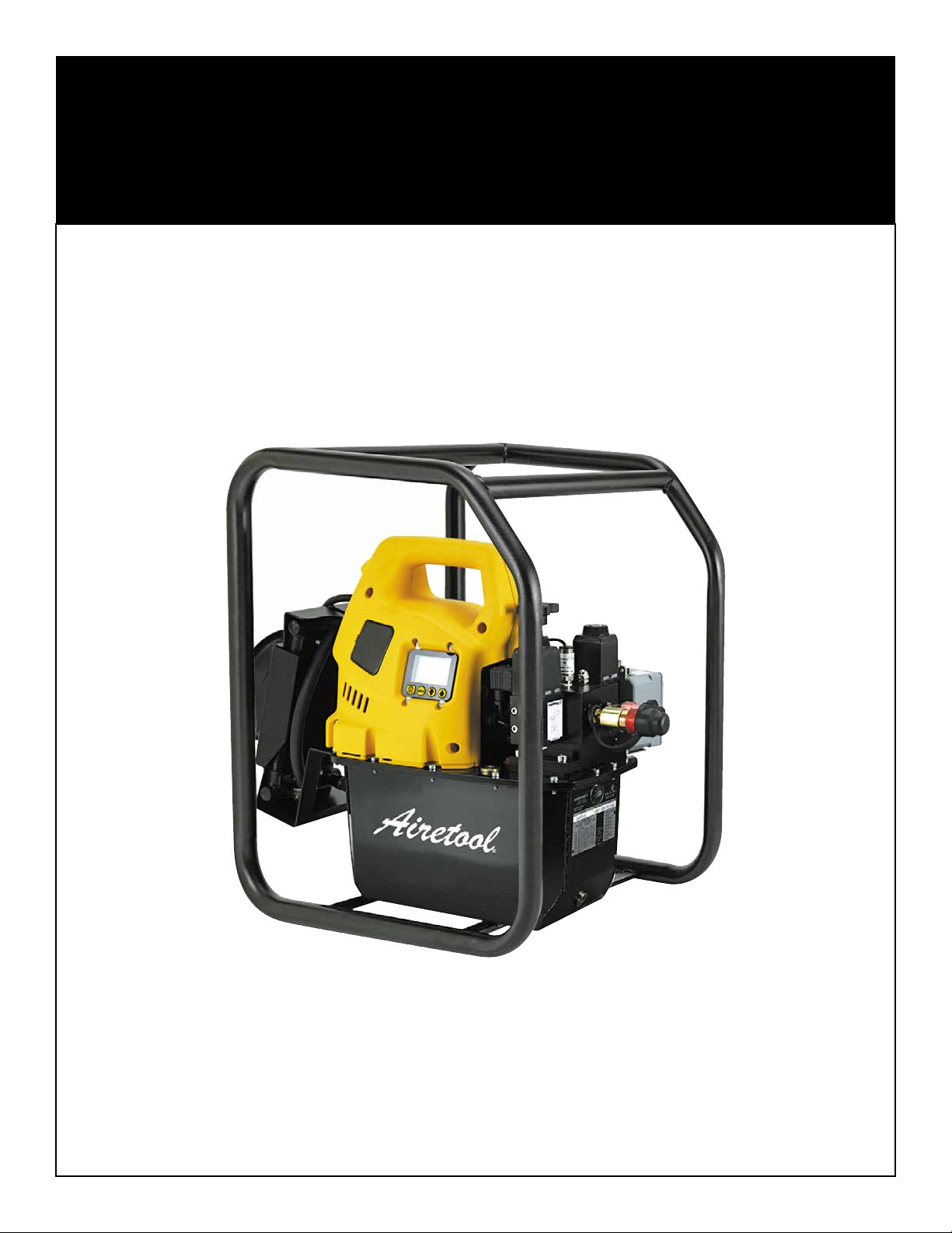
ATP III
Electric/Hydraulic Pump
Airetool®

Page 2
PL19-6000EN
05/15/2015
Airetool®
Specifications
Pump Model 5526244 (ATP III)
Motor 1.7 hp (1,25 kW) Electric Motor
Motor Voltage 115 VAC, Single Phase, 50/60 Hz
Motor RPM 1,750
Maximum Current Draw 20 Amps
100 psi (7 bar) = 700 in
3
/min (11,5 l/min)
700 psi (50 bar) = 535 in
3
/min (8,8 l/min)
5,000 psi (350 bar) = 76 in
3
/min (1,2 l/min)
10,000 psi (700 bar) = 60 in
3
/min (1,0 l/min)
Relief Valve Adjusment Range 1,400-10,000 psi (70-700 bar)
Sound Level 85-90 dBA
Reservoir Capacity 2 gallons (8 liters)
Weight (with oil) 70 lbs. (31.8 kg)
ATP III Electric/Hydraulic Pump Specifications
Output Flow Rate *
* Note: Output flow rate shown is at 60 Hz.
Flow rate will be approximately 5/6 of shown values at 50 Hz.
Figure 1
Page 3
PL19-6000EN
05/15/2015
Airetool®
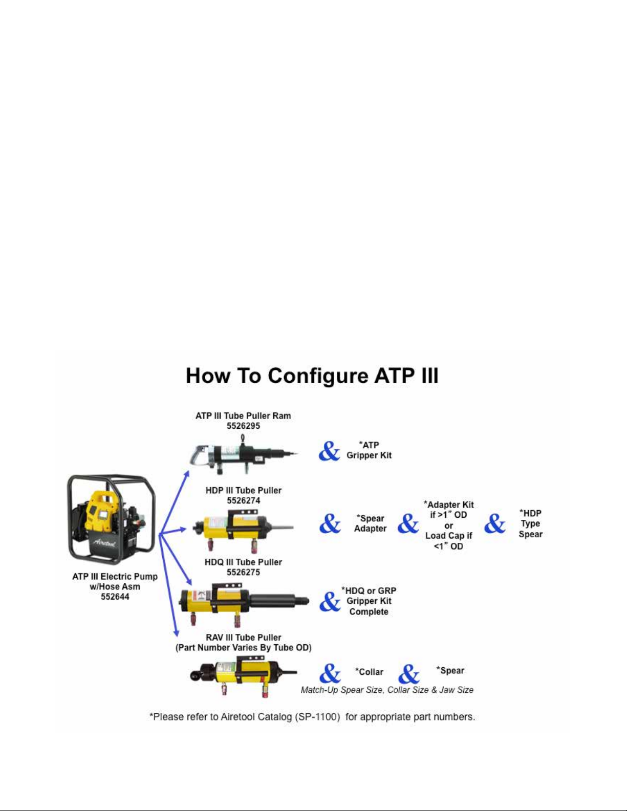
System Configuration
Carefully plan your system by selecting components designed to perform the intended operation
and which will adequately perform with existing equipment.
Always check the product limitations regarding pressure ranges, load capacities and set-up
requirements. The system operating pressure must not exceed the pressure rating of the lowest
rated component in the system.
Read all CAUTIONS, WARNINGS, and INSTRUCTIONS included with or attached to each
product. Follow all safety precautions to avoid personal injury or property damage during system
operation.
IMPORTANT RECEIVING INSTRUCTIONS:
Visually inspect all components for shipping damage. If any shipping damage is found, notify
the carrier at once. Shipping damage is NOT covered under the Apex Tool Group warranty. The
carrier is responsible for all repair or replacement cost resulting from damage during shipment.
Figure 2

Page 4
PL19-6000EN
05/15/2015
Language Version:
This Parts Manual is the “Original Instructions” intended
for all persons who will use or repair these tools.
Noise and Vibration:
The ATP III Pump operates at 85-90 dBA.
General Description:
An electric powered hydraulic pump mounted in a
wheeled roll cage, with an integrated handle, to facilitate
safely and easily moving the pump from one job location
to another.
Intended Use:
This pump is designed to work as an integrated tube
pulling system in conjunction with the Airetool ATP III
gripper type pullers. The Airetool HDQ III gripper type
pullers, RAV III and HDP III spear type tube pullers can
also be used with this pump.
Use only for the designated purpose. Do not use in any
improper manner that can cause equipment damage
and operator injury.
Copyright protection:
Apex Tool Group, LLC reserves the right to modify,
supplement or improve this document or the product
without prior notice. This document may not be
reproduced in any way, shape or form, in full or parts
thereof, or copied to another natural or machine readable
language or to a data carrier, whether electronic,
mechanical, optical or otherwise without the express
permission of Apex Tool Group, LLC.
Airetool®
Description
Page 5
PL19-6000EN
05/15/2015
Safety Precautions:
Read all instructions, warnings and
cautions carefully. Follow all safety
precautions to avoid personal injury or
property damage during system operation.
Apex Tool Group cannot be responsible
for damage or injury resulting from unsafe
product use, lack of maintenance or
incorrect product and/or system operation.
Contact Apex Tool Group when in doubt as
to the safety precautions and operations of
this equipment.
Failure to comply with the following cautions and
warnings could cause equipment damage and/or
personal injury.
A CAUTION is used to indicate correct operating or
maintenance procedures and practices to prevent
damage to, or destruction of, equipment or other
property.
A WARNING indicates a potential danger that requires
correct procedures or practices to avoid personal injury.
A DANGER is only used when your action, or lack of
action, may cause serious personal injury or
even death.
WARNING: Wear proper personal
protective gear when operating hydraulic
equipment.
WARNING: The system operating
pressure must not exceed the pressure
rating of the lowest rated component in
the system. Install pressure gauges in the
system to monitor operating pressure.
Avoid damaging the hydraulic hoses.
Avoid sharp bends and kinks when routing
the hydraulic hoses. Using a bent or kinked
hose will cause severe back-pressure.
Sharp bends or kinks will internally damage
the hose leading to premature failure.
DO NOT drop heavy objects on the
hoses. A sharp impact may cause internal
damage to the hose wire strands. Applying
pressure to a damaged hose may cause it
to rupture.
IMPORTANT: Do not lift hydraulic
equipment by the hoses or swivel couplers.
Use the integrated handle and wheeled
cage to safely move the pump.
Keep hydraulic equipment away from
ames and heat. Excessive heat will
soften packing and seals, resulting in uid
leaks. Heat also weakens hose materials
and packing. For optimum performance
do not expose equipment to temperatures
of 150° F (65° C) or higher. Protect hoses
and cylinders from weld spatter.
Do not handle pressurized hoses.
Escaping oil under pressure can penetrate
the skin, causing serious injury. If oil is
injected under the skin, see a doctor
immediately.
IMPORTANT: Hydraulic equipment must
only be serviced by a qualied hydraulic
technician. To protect your warranty, use
only manufactured recommended oil.
Immediately replace worn or damaged
parts with genuine manufacturer’s parts.
Standard grade parts will break causing
property damage and/or personal injury.
Manufacturer’s parts are designed to t
properly and withstand high loads.
Do not use electric pumps in an explosive
environment.Adhere to al local and national
electrical codes. A qualied electrician
must do installation and modication on
this equipment.
These pumps have internal factory
adjusted relief valves, which must not be
repaired or adjusted except by a factory
authorized service location.
To prevent damage to the pump’s electric
motor, check specications. An incorrect
power source will cause damage to the
motor.
Airetool®
Safety First

Page 6
PL19-6000EN
05/15/2015
Installation:
Position the pump to ensure that air ow around the
motor and pump is not obstructed. Keep the motor clean
to ensure maximum cooling during operation.
Fluid Level:
Check the oil level of the pump prior to start-up. If
necessary add oil by removing the SAE #10 plug from
the cover plate, Figure 3.
The reservoir is full when the oil level reaches the top of
the sight glass, Figure 4.
IMPORTANT: Add oil only when all system components
are fully retracted, or the system will contain more oil
than the reservoir can hold.
Operation:
Check the oil level of the pump and add oil if necessary,
as shown in Figures 3 and 4.
Connect power to the unit and wait until “OK” is displayed
on the LCD before pressing any button on the shroud or
pendent (if equipped).
NOTE: During the boot sequence, the micro processor
identies any button operation as a potential malfunction
and prevents the motor from starting. You can reset by
disconnecting the power for 10 seconds.
Start the motor and operate the tube puller by pressing
and releasing the ON/OFF button. The LCD will show
the pressure in the retract circuit (B-port bypass),
approximately 2500-2800 psi (173-193 bar).
As the motor starts, the valve shifts
automatically, retracting the tube puller.
Verify the tube puller is positioned to avoid
personal injury or equipment damage
before starting motor.
Shut off the motor by pressing the ON/OFF button. If
no buttons are pressed within a continuous 20 second
period, the pump’s built in timer will automatically shut
the motor off.
NOTE: When the motor is turned off, as the motor stops
turning, the valves will automatically cycle to release all
pressure in both the advance and retract hoses.
NOTE: Units equipped with heat exchangers allow the
timer to automatically shut off the pump. During any idle
period, the pump is circulating 90% of its oil ow through
the heat exchanger to reduce oil temperature.
Setting Pump Pressure:
This pump model provides the operator with two methods
of limiting the Advance (A port) pressure to the tube
puller: “User Adjustable Relief Valve” and “Auto Cycle”.
Airetool®
General Instructions
Figure 3: Oil Fill Plug
SAE #10
Plug
Figure 4: Oil Full Level
Reservoir
Full Level
Figure 5: Relief Valve
Control
Handle
Locking
Nut

Page 7
PL19-6000EN
05/15/2015
User Adjustable Relief Valve:
Limits the pressure by opening the relief valve to redirect
the pump’s oil ow to the reservoir at the desired
pressure value. Pressure will remain in the Advance
circuit (A port) while the Pendant “Up” button is pressed.
To adjust the pressure valve, Figure 5:
1. Verify “Auto Mode” is Off or “Set Pres” value is a
minimum 100 psi (7 bar) higher than the desired
relief valve setting.
2. Loosen the relief valve locking nut and turn the relief
valve control handle counter-clockwise until there
is a light drag when turning, this will decrease the
pressure value.
3. Start the pump to allow the oil to warm above 32°
F (0° C).
4. Press and hold the pendant Up button to build
pressure in the advance circuit. Turn relief valve
control handle clockwise to increase pressure to
desired value. NOTE: To get an accurate setting,
decrease the pressure to a point below the nal
setting and then slowly increase the pressure
until it reaches the nal setting.
5. Tighten the relief valve locking nut at the desired
pressure value.
6. Release the pendant Up button to allow the system
pressure to return to the B-port by-pass setting.
7. Recheck the nal pressure setting by shifting the
valve and pressurizing the system.
Auto Cycle:
Limits the pressure by automatically changing the tube
pulling operation from Advance to Retract at the desired
pressure value. When the Retract pressure reaches a
factory-preset value of approximately 2,000 psi (138
bar), the pump automatically changes tube pulling
operation from Retract back to Advance. The pump
microprocessor does this by shifting the electric control
valve to redirect the pump’s oil ow between ports. This
automatic cycling will continue while the pendant Up
button is pressed.
To activate Auto Cycle and adjust the pressure value:
1. Activate Auto Cycle by displaying the “Automode”
menu and toggling the setting to “On” using the
shroud arrow buttons. Save by pressing the Menu
button once.
2. Set the desired Advance pressure by displaying the
“Set Pres” menu and adjusting the value by using
the shroud arrow buttons. Save and return to the
“OK” display by pressing and holding the Menu
button for 2 seconds.
3. Turn on the pump by pressing the pendant On/Off
button.
4. Press and hold the pendant Up button to Auto Cycle
the tube puller.
5. If the tube puller does not Auto Cycle or does so
erratically, increase the User Adjustable Relief Valve
setting to a minimum value of 100 psi (7 bar) higher
than the desired Auto Cycle value.
NOTE: Maximum Retract pressure (B port),
also known as B port by-pass, is factory set at
approximately 2,500-2,800 psi (173-193 bar) and
cannot be adjusted.
LCD Function:
Besides the Pendant, which is used to switch the motor
on/off and operate the valves, the Control Board with its
four-button switches is the main interface between the
operator and the pump. With the use of these four-button
switches all functions and settings that are described in
the following can be activated.
Make sure that all the plastic overlay, that
protects the LCD screen and the button
switches, is not broken or otherwise
damaged. Never punch the button switches
with a sharp or pointed instrument, user
ngertips only. Clean the overlay regularly
with a damp cloth; never use an aggressive
or abrasive detergent.
Airetool®
General Instructions
Figure 6: LCD Screen
Number
Display
Text
Display
Page 8
PL19-6000EN
05/15/2015
A. Boot Sequence:
Firmware 5.5 and earlier: When the pump is
connected to electrical power the LCD screen will show:
“FIRMWARE x.x” for 2 seconds.
Firmware 5.6 and later: When the pump is connected to
electrical power the LCD screen will show: “FIRMWARE
x.x” for 1 second, then “Model xx” for 0.5 seconds, and
then “MOTOR UN/1P/3P” for 0.5 seconds.
This is setup information about your pump that may
be needed for service. The boot sequence is nished
successfully when the text display on the LCD screen
shows “OK” (sequence takes approximately 2 seconds).
The micro-controller will automatically recognize the
optional pressure transducer built into the pump. The
reading after the boot process is “OK” in the text display
and the current pump pressure on the numeric display.
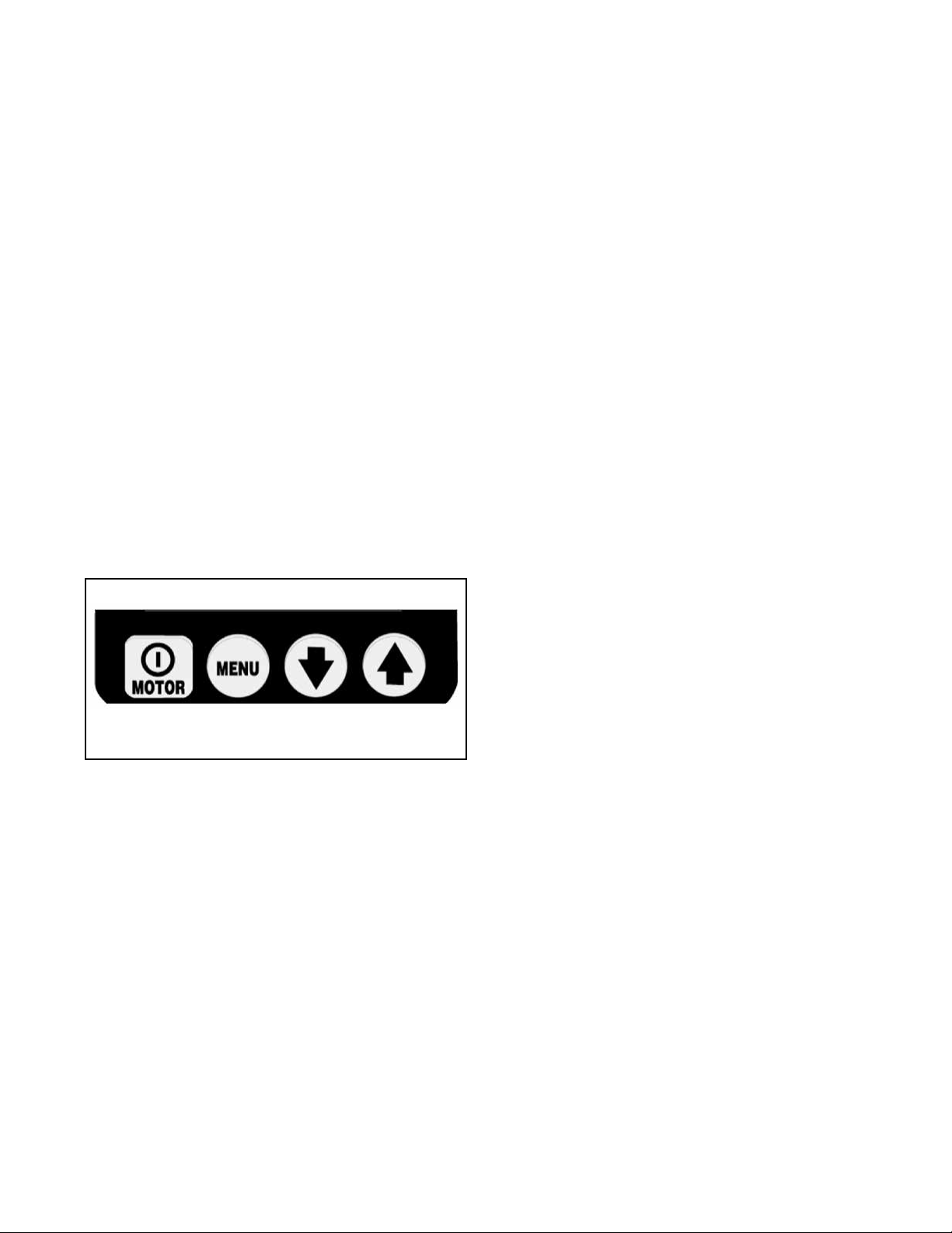
B. LCD Operational Buttons:
The control board is equipped with four button switches,
from left to right; On/Off, Menu, Down Arrow, Up Arrow,
see Figure 7.
• The On/Off button toggles the motor OFF. The
motor OFF function is available on this button even
if the pump is NOT in the local mode but is operated
by using the pendant control.
• The Menu button enables the operator to step from
normal operational mode into menus. With repeated
pressing the operator steps through the various
menus. Pressing the Menu button also saves any
changes made. To return to the normal operational
mode, press and hold the Menu button for two
seconds or don’t push any button for 60 seconds.
• The Down Arrow and Up Arrow buttons serve
two purposes. When the display shows one of the
menus, the Down Arrow and Up Arrow buttons are
used to step through the menu’s options. When the
pump is placed in Local Mode the UP Arrow button
switches the B and A electric solenoids (the pendant
is non-operational in local mode).
C. Menus Available:
The software provides the operator with the following
Menus:
• Automode: Set tube puller Auto Cycle mode ON
or OFF. With Automode OFF, the menu Set Pres
(Firmware 5.5 and earlier) or HI PRESS (Firmware
5.6 and later) will not be available and the Set Pres
or HI PRESS pressure value has no effect on the
pump.
• Set Pres or HI PRESS: (Only available with
Automode ON) Set the Advance port pressure
value the tub puller will Auto Cycle at. Changes in
increments of 50 psi (3.5 bar), maximum pressure
value is 10,000 psi (700 bar). NOTE: Firmware 5.5
and earlier - the hidden calibration menu for the
digital gauge is accessed from this menu.
• Units: Set the pressure units to PSI / BAR / MPa,
with psi being the default setting. NOTE: Firmware
5.6 and later - the hidden calibration menu for
the digital gauge is accessed from this menu.
• Motor: Display the motor hour meter and on/off
cycle counter (can not be reset).
• Low Volt: Display the low voltage hour-meter (can
not be reset).
• Advance: Display the Advance solenoid hour meter
and on/off cycle counter (can not be reset).
• Retract: Display the Retract solenoid hour meter
and on/off cycle counter (can not be reset).
• Local: Set the pump local mode on/off
• Language: Set the language of the display to
English / Spanish / French / Italian / German /
Portuguese, with English being the default setting.
• Diagnose: Display to show input signals from the
pendant control and other electrical accessories.
Fault Conditions:
Any fault will shut down and prevent the pump from
starting:
A. Clearing a Fault Condition from the LCD:
After the fault causing the problem has been corrected,
clear the fault message from the LCD by disconnecting
electrical power from the pump, wait until all characters
clear the LCD (approximately 10 seconds), then
reconnect the electrical power.
Airetool®
General Instructions
Figure 7: Operational Buttons
On/Off Menu Down
Arrow
Up
Arrow
Page 9
PL19-6000EN
05/15/2015
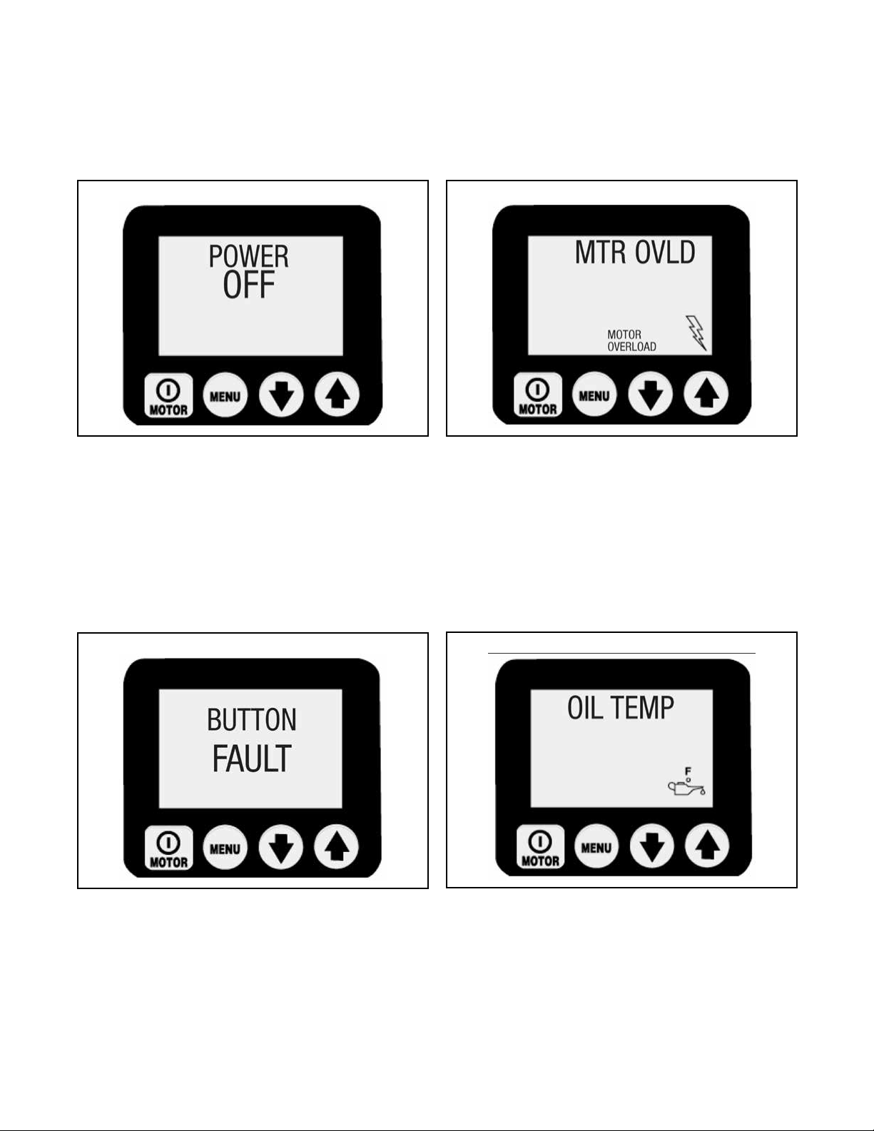
B. Power Failure:
Display: “POWER OFF”
The Power Off fault is displayed when the main power
supply drops to 65% or less of nominal voltage. The
pump will automatically shut off the valves and the
motor, and display “Power Off” on the LCD.
NOTE: “Power Off” is also displayed for several
seconds after the unit is disconnected from the
electrical supply.
C. Button Fault:
Display: “Button Fault”
The Button Fault is displayed when the micro processor
detects any button press during the boot sequence or
if the shroud on/off button is held in for more than 3
seconds.
D. Motor Overload:
Display: “MTR OVLD”
The Motor Overload fault is displayed when the electric
current drawn by the motor exceeds the pre-set limit of
the internal circuit breaker. The internal circuit breaker
will automatically reset once the condition has been
corrected; however, the operator must clear the fault and
then press the motor on/off button to restart the motor.
E. Oil Temperature (requires optional oat/temperature
switch)
Display: “OIL TEMP”
The Oil Temperature fault is displayed when the
temperature of the oil inside the reservoir exceeds 175°
F (80° C).
Airetool®
General Instructions
Figure 8: Power Off
Figure 9: Button Fault
Figure 10: Motor Overload
Figure 11: Oil Temperature
Page 10
PL19-6000EN
05/15/2015
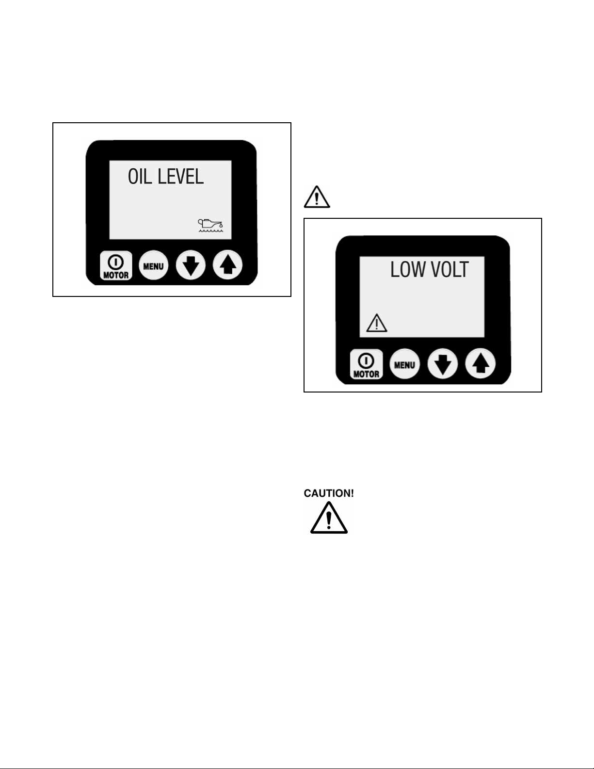
F. Oil Level (requires optional oat/temperature switch)
Display: “OIL LEVEL”
The Oil Level fault is displayed when the oil level inside
the reservoir drops below 1.3” (34mm) from bottom.
Warning Conditions:
All warnings notify the operator of an abnormal operating
condition, however, allow pump to continue operating.
Warnings will automatically clear once the issue has
been resolved.
A. Low Voltage:
Display: “LOW VOLT”
Low Voltage
A Low Voltage condition is dened as an operating
condition when the main power supply is at or below
80% of nominal voltage. While running the pump under
this condition, the “Low Voltage” signal will ash on the
LCD and the Low Voltage hours will be counted and
stored on the control board. Normal pump operation is
still provided.
For optimized pump performance it is
recommended NOT to run the pump at a
Low Voltage condition.
Airetool®
General Instructions
Figure 12: Oil Level
Figure 13: Low Voltage
Page 11
PL19-6000EN
05/15/2015
LCD Menus:
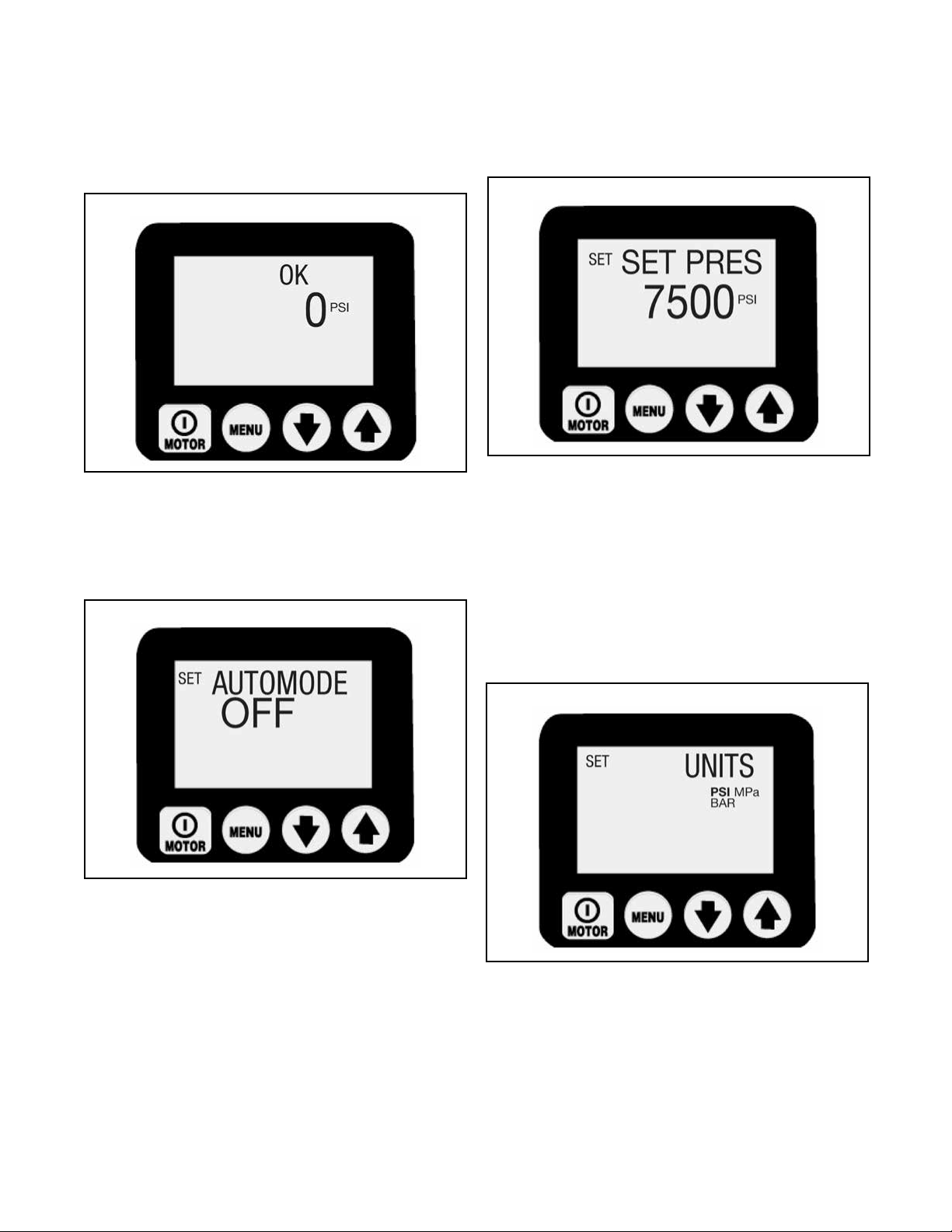
A. Normal Operation Menu:
The Normal Operation LCD screen indicates that
the control board has booted successfully (OK); the
pressure reading is 0 psi. The operator can now enter
into the menus by pressing the “Menu” button.
B. Auto Mode Menu:
This screen allows the operator to toggle the tube puller
Auto Cycle mode ON or OFF. With Automode OFF, the
menu Set Pres (Firmware 5.5 and earlier) or HI PRESS
(Firmware 5.6 and later) will not be available and the Set
Press / HI PRESS pressure value has no effect on the
pump. Switch it ON or OFF by pressing either the Down
or Up Arrow buttons.
NOTE: Firmware 5.6 and later - Setting the value to
ON also changes the Normal Operations menu text
message from “OK” to “AUTO”. Save the setting
and step forward by pressing the Menu button.
C. Set Press or High Press Menu (only available with
Automode ON):
This screen allows the operator to set the Advance
port pressure value the tube puller will Auto Cycle at.
Changes in increments of 50 psi (3.5 bar) by pressing
either the Down or Up Arrow button or keep either button
pressed for speed setting. Maximum pressure value is
10,000 psi (700 bar). Save the setting and step forward
by pressing the Menu button.
NOTE: Firmware 5.5 and earlier: The hidden
calibration menu for the digital gauge is accessed
from this menu.
D. Units Menu:
This screen allows the operator to set the unit of
pressure-measurement by pressing either the Down or
Up Arrow button. The options available are PSI, BAR,
Mpa with PSI being the default. Save the setting and
step forward by pressing the Menu button.
NOTE: Firmware 5.6 and later: The hidden calibration
menu for the digital gauge is accessed from this
menu.
Airetool®
General Instructions
Figure 14: Normal Operation Menu
Figure 15: Auto Mode Menu
Figure 16: Set Press or HI PRESS Menu
Figure 17: Units Menu

Page 12
PL19-6000EN
05/15/2015
E. Motor Menu:
This screen allows the operator to read the number of
hours (ON / OFF cycles) the motor has been operated.
Toggle between hours and cycles by pushing either the
Down or Up Arrow buttons. Step forward by pressing the
Menu button.
General note for all hour and cycle displays:
Hours Displayed
• up to 9999.9 the display will show decimal hours
• between 10,000 - 99,999 whole hours will be
displayed (decimal “.” is not displayed)
• over 99,999 hours the meter starts over at 0.0
reading decimal hours.
Cycles Displayed
• over 99,999 cycles the meter starts over at 0
F. Low Volt Menu:
This screen allows the operator to read the number
of hours the pump has been operated in low-voltage
condition. Step forward by pressing the Menu button.
G. Advance Menu:
This screen allows the operator to read the number of
hours (On / Off cycles) the Advance solenoid has been
operated. Toggle between hours and cycles by pushing
either the Down or Up Arrow buttons. Step forward by
pressing the Menu button.
H. Retract Menu:
This screen allows the operator to read the number of
hours (On / Off cycles) the Retract solenoid has been
operated. Toggle between hours and cycles by pushing
either the Down or Up Arrow buttons. Step forward by
pressing the Menu button.
Airetool®
General Instructions
Figure 18: Motor Menu
Figure 19: Low Volt Menu
Figure 20: Advance Menu
Figure 21: Retract Menu

Page 13
PL19-6000EN
05/15/2015
I. Local Menu:
This screen allows the operator to toggle the LOCAL
mode ON or OFF, default is OFF. With LOCAL mode
ON, the shroud buttons replace the pendant control
buttons as the method to operate the pump.
NOTE: The word LOCAL replaces OK on the Normal
Operations display and the pendant control buttons
become deactivated.
LOCAL mode will provide operation of the pump if the
pendant control or pendant control cable is damaged.
Toggle LOCAL mode ON or OFF by pressing the Down
or Up Arrow buttons. Save the setting and step forward
by pressing the Menu button.
J. Language Menu:
With a language shown on the text display the operator
can change the display language by pressing the Down
or Up Arrow buttons. Save the setting and step forward
by pressing the Menu button.
K. Diagnose Menu:
This screen allows the operator to trouble shoot several
pendant problems by displaying if the microprocessor
has received a signal from the pendant control button.
No signal indicates the problem is most likely with the
pendant keypad or pendant cord. Use LOCAL mode to
operate the pump until the problem can be corrected.
Airetool®
General Instructions
Figure 22: Local Menu
Figure 23: Language Menu
Figure 24: Diagnose Menu
not used
Fan
Pendant Down Arrow button
Pendant Up Arrow button
Pendant ON / OFF button
Figure 25: Diagnose Menu
ON / OFF (Motor)
button pushed
Up Arrow (Advance)
button pushed

Page 14
PL19-6000EN
05/15/2015
LCD Hidden Menus:
(available when the pressure transducer is installed)
A. Calibration Menu:
This screen allows the operator to adjust the pressure
value shown on the LCD to match a master gauge. To
access this menu:
Firmware 5.5 and earlier: Set AUTOMODE to ON and
go to the “Set Pres” menu.
Firmware 5.6 and later: Go to the UNITS menu
Then press and hold the ON / OFF button for 7 seconds,
ENTRY CODE will appear. Then press and hold both the
Down Arrow and Up Arrow buttons for 7 seconds.
Refer to Table A for Pump Calibration sequence.
Airetool®
General Instructions
Figure 26: Calibration Menu

Page 15
PL19-6000EN
05/15/2015
Step Operator Action Comments
1
Connect master gauge to port A (Advance port) - Also
connect hand pump if applicable, see comments
Note: There are two methods of producing the
needed pressure in steps 11 and 15, using the pumps
"motor" or separate "hand pump". Connect a hand
pump only if it will be used to create pressure in steps
11 and 15, and verify the pump's user adjustable
relief valve is set higher than maximum pressure
used in step 15.
2 Connect electrical power to pump FIRMWARE x.x, then "OK" 0 psi Boot-sequence
3
Firmware 5.5 and earlier: In the OK mode, press the
Menu button once and set Automode ON
AUTOMODE ON
If Automode is OFF, press one of the Arrow buttons
once to select ON
3.1
Firmware 5.5 and earlier: At main screen, press the
Menu button once to display screen "SET PRES",
skip step 4
SET PRES xxxx psi xxxx psi is the current pressure value of SET PRES
4
Firmware 5.6 and later: At main screen, press the
Menu button once to display screen "UNITS", skip
steps 3 and 3.1
UNITS psi psi is the current unit of pressure measurement
5 Press and hold the ON / OFF button for 7 seconds ENTRY CODE Step into the hidden calibration mode
6Press and hold the Up Arrow and Down Arrow
buttons together for 7 seconds
CAL PT A 0 psi (0 bar)
Start of calibration process. The advance-solenoid
will be powered up to access the pressure transducer
through valve-port A.
7.a
"Motor" method - Open the pump's user adjustable
relief valve and verify both pump LCD and master
gauge read zero.
CAP PT A 0 psi (0 bar) Calibrate the zero-offset, point "A"
7.b
"Hand Pump" method - Open the hand pump's user
control valve and verify both pump LCD and master
gauge read zero.
CAP PT A 0 psi (0 bar) Calibrate the zero-offset, point "A"
8
Press the Menu button to accept the pressure value
into temporary memory
SAVE A no
9
Press one Arrow button to change from "NO" to
"YES"
SAVE A yes
Confirm the pressure data should be stored to
memory
10 Press the Menu button once CAL PT B 2000 psi (138 bar)
Calibrating gain is done with two points, starting with
point "B"
11.a
"Motor" method - Press and release the shroud's ON
/ Off motor button to switch the pump motor on.
Reading the master gauge, apply a pressure of 2,000
psi (138 bar) by closing the pump's user adjustable
relief valve.
CAL PT B 2000 psi (138 bar)
CAL PT B can be set at any pressure value greater
than zero. First obtain the pressure value on the
master gauge (ie 2250 psi) (155 bar) then use the
arrow buttons to match the LCD value to the master
gauge.
11.b
"Hand Pump" method - Close the hand pump's
control valve. Reading the master gauge, apply a
pressure of 2,000 psi (138 bar)
CAL PT B 2000 psi (138 bar)
CAL PT B can be set ay any pressure value greater
than zero. First obtain the pressure value on the
master gauge (ie 2250 psi) (155 bar) then use the
arrow buttons to match the LCD value to the master
gauge.
12
Press the Menu button to accept the pressure value
into temporary memory
SAVE B no
13
Press one Arrow button to change from "NO" to
"YES"
SAVE B yes
Confirm the pressure data should be stored to
memory
14 Press the Menu button once CAL PT C 8000 psi (548 bar)
Calibrating gain is done with two points, finishing with
point "C"
15
Reading the master gauge, apply a pressure of 8,000
psi (548 bar) CAL PT C 8000 psi (548 bar)
CAL PT C can be set at any pressure value greater
than CAL PT B. First obtain the pressure value on the
master gauge (ie 7500 psi) (515 bar) then use the
arrow buttons to match the LCD value to the master
gauge.
16
Press the Menu button to accept the pressure value
into temporary memory
SAVE C no
17
Press one Arrow button to change from "NO" to
"YES"
SAVE C yes
Confirm the pressure data should be stored to
memory
18 Press the Menu button once USE DFLT off
Re-confirm calibration data. Leave "off" to proceed
with new calibratin data. Only set to "on" to change
calibration data back to factory default settings. Press
Arrow button to change.
19 Press the Menu button once CAL PT A 0 psi (0 bar) Save calibration data to permanent memory.
20
Press and hold the Menu button for 3 seconds to step
out of the calibration mode.
OK 0 psi (0 bar) Calibration complete
Table A - Pump Calibration
LCD Reading
Airetool®
General Instructions

Page 16
PL19-6000EN
05/15/2015
Maintenance:
Frequently inspect all system components for leaks
or damage. Electrical components (example; power
cord) may only be repaired or replaced by a qualied
electrician, adhering to all applicable local and national
codes.
Check Oil Level:
Check the oil level of the pump prior to start-up, and add
oil, if necessary, by removing the oil ll plug. Always be
sure the cylinders are fully retracted before adding oil to
the reservoir.
Change Oil and Clean Reservoir:
The ATP III pump oil is a crisp blue color. Frequently
check the oil condition for contamination by comparing
the reservoir oil to new unused oil. As a general rule,
completely drain an clean the reservoir every 250 hours
of use, or more frequently if used in dirty environments
NOTE: This procedure requires that you remove the
pump from the reservoir. Work on a clean bench and
dispose of used oil according to local codes.
1. Unscrew the 13 bolts holding the cover plate to the
reservoir and lift the pump unit out of the reservoir.
Be careful not to damage the lter screen.
2. Pour all oil out of the reservoir.
3. Thoroughly clean the reservoir and magnet with a
suitable cleaning agent.
4. Remove the pick-up lter screen for cleaning.
CAUTION: Do not pull on the screen or the
bottom of the intake to avoid possible damage.
Clean the screen with solvent and a soft brush.
Reinstall the lter screen.
5. Reassemble the pump and reservoir, installing a
new reservoir gasket.
6. Fill the reservoir with clean manufacturer
recommended hydraulic oil. The reservoir is full
when the oil level is in the middle of the sight gauge,
see Figure 28.
Troubleshooting Guide (see Table B):
Only qualied factory technicians should service the
pump or system components. A system failure may or
may not be the result of a pump malfunction. To determine
the cause of the problem, the complete system must be
included in any diagnostic procedure.
The information contained in Table B is intended for use
as an aid in determining if a problem exists. For repair
service, contact your Apex Tool Group representative.
Airetool®
General Instructions
Figure 27: Oil Fill Plug
Oil Fill
Plug
Figure 28: Oil Full Level
Reservoir
Full Level

Page 17
PL19-6000EN
05/15/2015
Problem Possible Cause
Pump will not start No power or wrong voltage
Pump in LOCAL mode
Pendant damaged
Motor stalls under load Low voltage
No power or wrong voltage
Valve out of adjustment
Solenoid cable disconnected or damaged
Low oil level
External system leak
Internal leak in pump
Internal leak in valve
Internal leak in system component
Relief valve set too low
Low oil level
External system leak
Internal leak in pump
Internal leak in valve
Internal leak in system component
Relief valve set too low
Quick coupler not connected properly
Defective quick connector on pump or hand piece
Defective directional valve
External system leak
Internal leak in system component
Valve malfunction
Return flow or coupler restricted
Leaky seal(s) in hand piece
Couplings assembled backwards
Auto Cycle mode set to OFF
Relief valve setting at or below "SET PRES" or "HI
PRESS" value
SET PRES value below 2,900 psi (200 bar) -
Firmware 5.5 and earlier
HI PRESS value below 1,400 psi (96 bar) - Firmware
5.6 and later
Retract flow restricted or blocked
Valve malfunction
Advance or retract flol restricted
High ambient temperature
Pump runs hot
Tube puller does not Auto Cycle or Auto Cycles
erratically
Table B - Trouble Shooting Guide
Pump builds less than full pressure
Pump builds full pressure but does not move cylinder
Tube puller will not retract
Cylinder drifts back on its own
Cylinder will not return
Electric valve will not operate
Pump fails to build pressure
Pendant does not function
Airetool®
General Instructions
Page 18
PL19-6000EN
05/15/2015
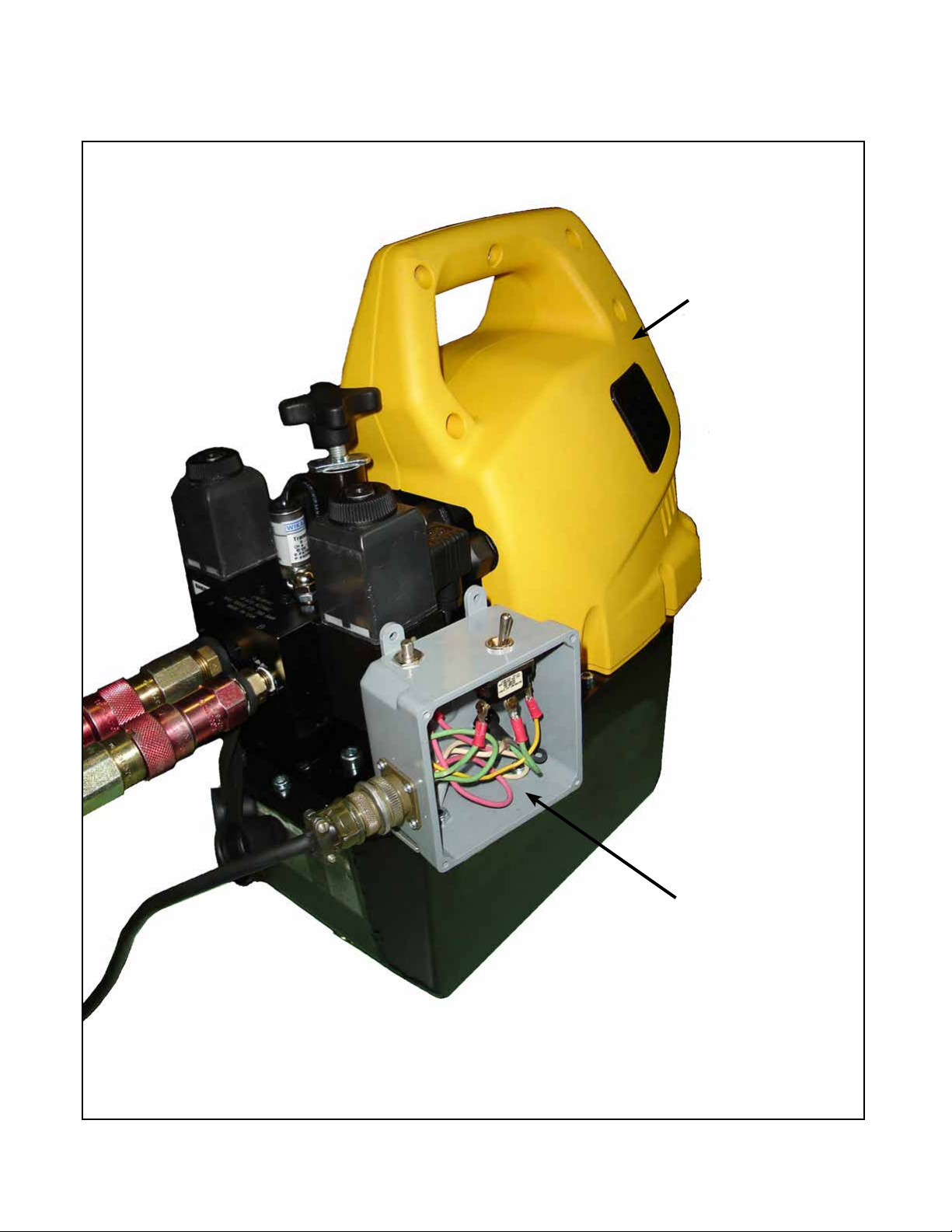
Page 18
Figure 29
1
Airetool®
Electric/Hydraulic Pump Assembly
2

PL19-6000EN
05/15/2015
Page 19
EN
Description
1 2902536 1 EDHP III Electric/Hydraulic Pump Assembly (Factory repair only)
2 ------ Serviceable Electrical Components
2994951 1 HDP 31 20 Receptacle
8567132 1 A 100 82 Reverse Switch
2983261 2 ATS 8835 Cable Clamp
2991255 1 ATP 9046 Cord Plug
2990688 1 A 100 95 Plug
2902574 1 PATP3 9 Plate
2902575 1 PATP3 4 BL Blank Box
8011043 4 4-20 x 3/8 Screw
2990308 1 A 100 66 Strain Relief
8010464 1 30 071 Wire Nut
8566942 1 AART 2 Receptacle
0981264PT 1 DAS2 Blank Box
2902576 1 ATP3 2 Switch
3 ------ Pump Mobility Parts mounted to Roll Cage (not shown)
2902841 1 ATP3 14 Axle
2902842 8 ATP3 15 U-Bolt
2902843 16 ATP3 16 Cap
2902844 2 ATP3 17 Caster
2902845 1 ATP3 18 Caster Bracket
2902846 2 ATP3 19 Wheel
(#) Quantity
(X) Recommended Spare Parts
Figure 29
Ref Number # X
Airetool®
Electric/Hydraulic Pump Assembly

Please note that all locations may not service all products.
Contact the nearest Apex Tool Group Sales & Service Center for the appropriate facility
to handle your service requirements.
POWER TOOLS SALES & SERVICE CENTERS
Apex Tool Group, LLC
1000 Lufkin Road
Apex, NC 27539
Phone: +1 (919) 387-0099
Fax: +1 (919) 387-2614
www.apexpowertools.com
England
Apex Tool Group
GmbH & Co. OHG
C/O Spline Gauges
Piccadilly, Tamworth
Staffordshire B78 2ER
United Kingdom
Phone: +44 1827 8727 71
Fax: +44 1827 8741 28
EUROPE | MIDDLE EAST | AFRICA
France
Apex Tool Group S.A.S.
25 rue Maurice Chevalier
B.P. 28
77831 Ozoir-La-Ferrière
Cedex, France
Phone: +33 1 64 43 22 00
Fax: +33 1 64 43 17 17
Germany
Apex Tool Group
GmbH & Co. OHG
Industriestraße 1
73463 Westhausen
Germany
Phone: +49 (0) 73 63 81 0
Fax: +49 (0) 73 63 81 222
Hungary
Apex Tool Group
Hungária Kft.
Platánfa u. 2
9027 Györ
Hungary
Phone: +36 96 66 1383
Fax: +36 96 66 1135
NORTH AMERICA | SOUTH AMERICA
Lexington, South Carolina
Apex Tool Group
670 Industrial Drive
Lexington, SC 29072
Phone: +1 (800) 845-5629
Phone: +1 (919) 387-0099
Fax: +1 (803) 358-7681
Canada
Apex Tool Canada, Ltd.
7631 Bath Road
Mississauga, Ontario L4T 3T1
Canada
Phone: (866) 691-6212
Fax: (905) 673-4400
Mexico
Apex Tool Group
Manufacturing México
S. de R.L. de C.V.
Vialidad El Pueblito #103
Parque Industrial Querétaro
Querétaro, QRO 76220
Mexico
Phone: +52 (442) 211 3800
Fax: +52 (800) 685 5560
Detroit, Michigan
Apex Tool Group
2630 Superior Court
Auburn Hills, MI 48236
Phone: +1 (248) 393-5640
Fax: +1 (248) 391-6295
Brazil
Apex Tool Group
Ind. Com. Ferram, Ltda.
Av. Liberdade, 4055
Zona Industrial Iporanga
Sorocaba, São Paulo
CEP# 18087-170
Brazil
Phone: +55 15 3238 3820
Fax: +55 15 3238 3938
Louisville, Kentucky
Apex Tool Group
1000 Glengarry Drive
Suite 150
Fairdale, KY 40118
apexpowertools.com/service
ASIA PACIFIC
India
Apex Power Tools India
Private Limited
Gala No. 1, Plot No. 5
S. No. 234, 235 & 245
Indialand Global
Industrial Park
Taluka-Mulsi, Phase I
Hinjawadi, Pune 411057
Maharashtra, India
Phone: +91 020 66761111
Australia
Apex Tool Group
519 Nurigong Street, Albury
NSW 2640
Australia
Phone: +61 2 6058 0300
China
Apex Power Tool Trading
(Shanghai) Co., Ltd
Building A8, No. 38
Dongsheng Road
Pudong, Shanghai
China 201201
Phone: +86 21 60880320
Fax: +86 21 60880298
Japan
Apex Tool Group Japan
Korin-Kaikan 5F,
3-6-23 Shibakoen, Minato-Ku,
Tokyo 105-0011, JAPAN
Phone: +81-3-6450-1840
Fax: +81-3-6450-1841
Korea
Apex Tool Group Korea
#1503, Hibrand Living Bldg.,
215 Yangjae-dong,
Seocho-gu, Seoul 137-924,
Korea
Phone: +82-2-2155-0250
Fax: +82-2-2155-0252
PL19-6000EN | 0515 | © 2015 Apex Tool Group, LLC | Printed in USA
Airetool®
Table of contents
Other Airetool Water Pump manuals

Popular Water Pump manuals by other brands

Graco
Graco BLUE DEVIL 260410 Instructions-parts list

Aqueon
Aqueon QuietFlow 10 instructions

laguna
laguna TABLETOP instructions

Summit
Summit 2175 Series Installation, operation and maintenance manual

Ruhrpumpen
Ruhrpumpen CPP21 Installation, operation and maintenance manual

Zehnder Pumpen
Zehnder Pumpen Drain Inox 50 MA operating instructions


