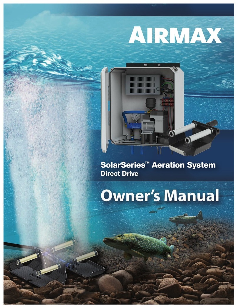
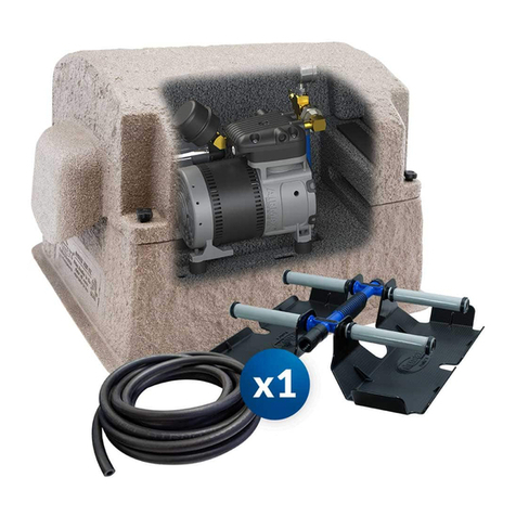
Airmax SolarSeries SS20-BB User manual

SolarSeries™Aeration System
Battery Backup

Important Safety Instructions
• Never operate the system if unusual noises or odors are detected. Turn the internal
and external shut-off switchs to the OFF position and call for service.
• This appliance is not intended for use by persons (including children) with reduced
physical, sensory, or mental capabilities, or lack of experience and knowledge,
unless they have been given supervision or instruction concerning the use of the
appliance by a person responsible for their safety.
• Children should be supervised to ensure that they do not play with the appliance.
GROUNDING INSTRUCTIONS –This product must be grounded according to the
procedures outlined in the installation section(s). Grounding reduces the risk of
electric shock by providing an escape wire for the electric current. This product is
supplied with a grounding wire and harnesses with appropriate grounding features.
WARNING
Check with a qualified electrician or serviceman when grounding instructions are
not completely understood or when in doubt as to whether the product is properly
grounded. Do not modify the grounding equipment provided with the system.
• Read all assembly and operating instructions carefully.
• To reduce the risk of electric shock, ensure cabinet shut-off switch is in the OFF
position when connecting solar panel wiring or conducting any maintenance on the
system.
• Repair or exchange of cables/power cords must be carried out by the supplier/
manufacturer or certified repair technician.
• This unit has not been evaluated for use in swimming pool areas
• Airmax is not responsible for equipment damage or failure, losses, injury or death
resulting from failure to follow safety precautions, misuse or abuse of equipment.
CAUTION
• Never attempt to modify system to run on any power source other than the provided
Airmax SolarSeries equipment.
• Do not allow anything to rest on the power cords/cables
• Do not place the cabinet or solar panel mounting system in a direct traffic path.
• Never override or “cheat” any electrical or mechanical devices.
• Never attempt any maintenance function that is not specified in the user manual.
See Video Instructions of the
Airmax SolarSeries Areation
System Installation Online
SolarSeries Aeration System
BATTERY BACKUP
OWNER’S MANUAL FOR:
SECTION
TABLE OF CONTENTS
PAGE
1 System Components 3-4
2 System Installation 5-16
A.) Tools Required 5
B.) Select Location for the 5
EasyMount System
C.) Post & Airline Installation 6-7
D.) EasyMount Main Assembly 7-8
Installation
E.) Solar Panel Installation 9-11
& Grounding
F. ) Cabinet Installation & Wiring 12
G.) Connect Airlines 13
H.) Install ProAir Diffusers 14-15
I.) Finalize System Install 15-16
3 Initial Start-Up & 17-18
Seasonal Operation
4 Maintenance 18
5 Troubleshooting 19
6 Replacement Parts 20-21
7 Warranty 22
2

*Depending on the type of installation, additional connector kits
may be required. See section 6 for connector kits.
SolarSeries Aeration System
Owner’s Manual
SolarSeries Aeration Components
SolarSeries Solar Panel Components
ProAir®2 Weighted Diffuser
SolarSeries Battery
Backup Cabinet
SolarSeries
Solar Panels (2)
MC4 Cables
(pre-wired leads on back
of each panel)
EasySet™Airline
Battery (2x), and
MPPT Controller
1. System Components
SolarSeries SilentAir
Diaphragm Compressor
• Self-Weighted Airline: 5/8” 100’ Roll (#510119):
Lead-free weighted airline is made of durable PVC
composite. Fish hook resistant and kink-free. Use
from pond’s edge to diffuser.
• Direct Burial Airline (sold separately): 5/8” 100’ Roll
(#510120) Flexible, yet kink-free. Bury from control
panel and compressor to pond’s edge when
placing the control panel and compressor away
from the pond.
3

C) Airmax EasyMount™ Assembly Components
D) Grounding Hardware
1. System Components - Continued
1
5
2
6
4
3
Grounding Wire
12’ Grounding Wire (1)
Grounding Lugs (2) Ground Rod Clamps
1/2” Ground Rod Clamps (2)
Cable Ties (12)
1. EasyMount Main Assembly (1)
2. Panel Support Rail Extension
with Hardware (2)
3. Tilt Support Hardware (2)
4. U-Bolts with Hardware (2)
5. Solar Panel Clamp, Single-Sided (4)
6. Solar Panel Clamp, Double-Sided (2)
4

2. System Installation
Running
Amps Volts Max CFM Power Cord Max Pond Size Max Depth # Diffusers
SS20-BB 2 24v 1.0 N/A 2 Acres 20' 2
Tech Specs:
*Ponds greater than 2 Acres require multiple systems
Option A
Pond’s Edge
Option B
Away From
Pond’s Edge
No Direct Burial Needed
• Ensure that holes for the solar mounting pole will not interfere with any underground utilities.
• Locate the system away from irrigation sprinklers.
*Attention: For airline runs longer than 100’, connector kits are required (sold separately) See Replacement Parts (Pages 20-21)
Direct Burial or Remote Manifold Needed
Use a single airline from cabinet to shoreline
with valves at pond’s edge.
B) Select a Location for the Airmax EasyMount System
Learn about installing an optional
Remote Manifold Kit online at
airmaxeco.com/RemoteManifold
Option B with Remote Manifold
See Video Instructions of the
Airmax SolarSeries Aeration
System Installation Online
TOOLS
• Post Pounder
• Sledge Hammer
• Post hole digger or auger
• Wheelbarrow
• Shovel
• Rake
• Step Ladder
• 1/2” Drill (cordless or electric)
• 1/4” x 6” drill bit
• 5/8” x 6” drill bit
• 7/16” socket and ratchet
• 7/16” wrench
• 1/2” wrench
• 3/4” deep-well socket and ratchet
• 3/4” wrench
• 5/16” nut driver or wrench
• #2 Phillips screwdriver
• #2 slotted screwdriver
• Tape measure
• Marker or pencil
• 4’ level
• Cable cutters
• C-clamps or bar clamps (2 with a minimum 4” throat depth)
• Boat or raft
• Coast Guard-approved life jacket
• Compass (or smart phone with compass app)
• Cardboard/blankets/towels to block solar panel energy during installation)
• 6-8 gallons of cold water (bucket or hose)
HARDWARE
• 2-1/2” dia. x 10’ (min) Schedule 40 Galvanized Steel Pole
(2.875” O.D. / 2.47” I.D.)
• 1/2” dia. x 8’ copper grounding rod
• 1/2” dia. x 8” rebar (2) (recommended)
• Concrete bags - 60 lb (5) or 80 lb (4)
• 2 x 4 wooden block (6” - 8” long)
• 2 x 4 x 8’ wooden studs for bracing posts during concrete cure time (4)
• 24” wooden stakes (4)
• 3” wood screws w/ appropriate drill tip (Torx, Phillips, etc)
• Electrical or duct tape
5

Fig. 8
2. System Installation - Continued
C) Post & Airline Installation
1) Select a solar panel mounting location well above the high-water mark of the
pond/lake with optimum southern exposure. Be sure that mounting location is
clear of anything that may obstruct exposure such as trees & shrubbery,
buildings, privacy fences, etc. (Fig 1).
2) Offset from Magnetic South: Often referred to as magnetic declination,
your east/west pivot is determined by the difference between magnetic south
(compass) and solar south (true south/south pole). First, start by using the
National Oceanic and Atmospheric Administration (NOAA) website below to
determine your declination (Fig. 2).
https://www.ngdc.noaa.gov/geomag/calculators/magcalc.shtml
Simply enter the site zip code in the Location field, click Get & Add Lat/Lon.
Once the information auto-fills, click Calculate to find your declination. Be sure
to note your latitude, as it will be used in a later step.
For example, zip code 48005 (Armada, MI):
Latitude = 42°, Declination = 7° 45’ W.
3) Use a post-hole digger or auger to create a 10” - 12” diameter hole,
36” deep (min). This should leave you with approximately 84” above grade for
your EasyMount Assembly.
Note: the hole can be bell-shaped at the bottom, but never at the top.
4) Use a 5/8” drill bit to drill a hole through the pole 8”–10” up from the bottom (it
may be helpful to pre-drill a pilot hole with a smaller drill bit first). Insert 1/2”
rebar into the hole so that an equal amount shows out eachside. Keep the rebar
in place with electrical tape/duct tape or a zip tie to keep it centered until post is
set. This step is important to keep the post from rotating in the concrete under
high wind conditions. We also advise against use of pre-cut cardboard tubes
inside the holes for the same reason; the use of such tubes can lead to the entire
cylinder of concrete rotating under windy conditions (Fig. 4).
5) Mix concrete and water in wheelbarrow according to the
manufacturer’s specifications.
6) Place the pole in the center of the hole and pour concrete into the hole until it
is 4”–6” inches below grade; keeping concrete slightly below grade will prevent
curbing, which can lead to heaving during springtime frost in colder climates.
7) Plumb pole with a level and brace using 2x4 studs, clamps and stakes
(recommended). Allow a minimum of 48 hours’ cure time before installing
the Airmax EasyMount Assembly and solar panels.
8) Next, drive an 8’ grounding rod into the ground 6”-8” away from the edge of
the concrete. Use the proposed cabinet location to determine the placement
of the grounding rod so that it is near the cabinet shut off switch (Fig. 8). Leave
approximately 6” of the rod exposed above grade. This rod will be used later in
the grounding section of the installation procedure.
Note: Grounding rods can be driven below grade after the rest of the system
is installed and properly grounded. We also recommend placing the cabinet
near the post mount assembly as shown below so that the solar panels
provide shade for the cabinet.
Obstruction Line
Winter Production
@ 45º Latitude
50' Tall
Obstruction
Winter Production
@ 30º Latitude
Solar Panels
Solar Panels
80' Clearance Minimum
160' Clearance Minimum
45º
West
45º
East
Fig. 1
Isogonic Lines Show the Pattern of Magnetic Declination
Fig. 2
10 - 12"
8 - 10"
84"
36"
1/2"
Rebar
Fig. 4
9) Before installing your EasyMount Assembly, we recommend trenching and
placing your airline. Begin by trenching from one side of the post hole to the
pond’s edge, approximately 8” deep. The trench can be 10”-12” to one side of
the post hole so as not to disrupt the curing concrete.
6

10) Place airline in the trench from the pond’s edge to the post making sure to leave
2’-3’ extra for connections to the control panel hoses once it is mounted in a later
step (Fig. 10).
Option A: (when distance between control panel and shore is less than 5’)
Use EasySet weighted airline. There must be a separate run of airline for each
diffuser that will be installed. Leave remaining airline coiled at the pond’s edge.
D) EasyMount Main Assembly Installation
1) Using a pencil or permanent marker, mark the post approximately 3” down from
the top on the south side.
2) If installing with one person, we recommend clamping a 2x4 block to the post
at the 3” mark using a large clamp. This block will provide a shoulder/shelf for
the upper beam of the EasyMount Main Assembly to rest on while installing the
U-bolts in Step 3 (Fig. 2).
3) First, rest the EasyMount Main Assembly upper beam on your clamp/block and
secure in place using the two U-bolts, washers, lock washers and nuts. Tighten
one half turn past hand tight using a 3/4” deep-well socket wrench. Secure the
lower pole mount beam with the second U-bolt and tight one half turn past hand
tight. Leave the U-bolts loose enough to pivot the assembly (Fig. 3).
4) Next, pivot the EasyMount assembly in the desired direction to face solar south,
based on the recommended angle for your region, and tighten all four U-bolts
securely using a ¾” deep well socket wrench.
5) Use the latitude of your region to set the optimal tilt angle (Fig. 5A). Some smart
phone compass apps will include your latitude and longitude on the screen,
OR you can refer back to the NOAA website from the previous section to find
your latitude.
a) If you will not be running your system in winter months, then simply use
your latitude as your reference point and set your tilt angle to the angle closest
to your latitude (i.e. 42° latitude = 40° tilt angle setting).
b) If you plan to run your system all year, use your latitude and add between
10º–15º when setting your tilt angle to get optimum performance when
daylight hours are at their shortest. For example, 42° latitude could be set to
the 55° or 60° setting on the EasyMount support rail; this will give you the
optimum tilt angle in winter months when daytime hours are considerably
shorter (Fig. 5B).
Note: Airmax recommends leaving your tilt angle set for optimum
performance during the winter months when daylight hours are
reduced by nearly 50%. The solar panels will receive ample sunlight in
the other seasons to effectively power the system even when adjusted
for winter operation.
Direct Sunlight
Solar Panel
(side view)
45º Tilt20º Tilt
RECOMMENDED TILT ANGLE
Latitude Tilt Angle Setting
0° to 19° (Vietnam – Thailand) 25° or 30°
20° to 25° (Hawaii – S. Florida) 35° or 40°
26° to 30° (S.Texas – N. Florida) 40° or 45°
31° to 35° (Mid-Texas – N. Georgia) 45° or 50°
36° to 40° (S. Nevada – New Jersey) 50° or 55°
41° to 45° (S. Idaho – Northern Michigan) 55° or 60°
46° to 50° (S. Washington – S. Canada) 60°
51° to 65° (S. Canada - Northern Alaska) 60°
Fig. 5A
Fig. 5B
Fig. 2
Fig. 3
2. System Installation - Continued
Fig. 10
Option B: (when distance between control panel and shore is more than 5’)
Use Direct Burial airline. There must be a separate run of airline for each diffuser
that will be installed. Join multiple sections of direct burial airline using 5/8”
connector kits. First, slide two hose clamps onto one section of airline. Next insert
the 5/8” insert adapter halfway into one section of airline and then insert into the
next section of airline. Using a flathead screwdriver or nut driver, secure one of the
hose clamps onto each half of the insert adapter.
Option B with Remote Manifold:
Refer to the Remote Manifold Kit manual or watch the installation video at
airmaxeco.com/RemoteManifold for more information.
11) Backfill the trench in a few places to keep airline in place.
7

6) Next, remove the tilt support hardware from the temporary location on the support
rail. Align the hole on the tilt support strut with the desired hole on the support
rail (Fig. 6A) . The recommended angles shown in the table (Fig. 5B) are based
off the difference from the horizontal plane. Tighten completely using two 3/4”
wrenches (Fig. 6B). Repeat for the opposite side.
7) Continue by installing a panel support rail extension. First, remove the bolts, lock
washers and nuts from the end of the rail extension connector to attach to the
panel support rail. Tighten using one 7/16” wrench and one 7/16” socket wrench
(Fig. 7). Repeat for the opposite side.
8) Lastly, tighten the four pivot bracket bolts using a 3/4” socket wrench (Fig. 8).
2. System Installation - Continued
Fig. 6A Panel Support Rail
25º
30º
35º
40º
45º
50º
55º
60º
Tilt Support Strut
Fig. 6B
Fig. 7
Fig. 8
8

2. System Installation - Continued
E) Solar Panel Installation & Grounding
CAUTION: To prevent possible injury, cover solar panels with either
cardboard, blankets, or towels to prevent any voltage transmission through
solar panel cables during installation.
Avoid installing solar panels on windy days to prevent possible accidental
damage to equipment.
1) First, position a single-sided solar panel clamp at the bottom edge of one panel
support rail extension and tighten using a 7/16” wrench. Do not tighten the top hex
bolt as you will need room to slip the bottom edge of the solar panel frame into the
clamp (Fig. 1). Repeat for the second panel support rail extension.
2) Temporarily position one double-sided solar panel clamp at the joint between the
panel support rail and the rail extension; hand tighten only at this time (Fig. 2).
Place the second double-sided clamp in the same position on the opposite
support rail.
3) Next, position a single-sided solar panel clamp at the top edge of one panel support
rail and hand tighten only (Fig. 3). Repeat for the last single-sided clamp.
4) Position the first solar panel so that it rests on the lower single-sided clamps. It
does not matter which side the wiring junction box faces, as long as the second
solar panel is positioned in the same manner once installed in Step 6. See
orientation in (Fig. 4). After ensuring the solar panel frame is seated beneath both
clamps, hand tighten each clamp.
Note: We recommend using two people when handling and installing
solar panels.
Fig. 2
Fig. 1
Fig. 3
Fig. 4
9

5) Next, loosen the double-sided clamp from the rail on each side. Then position the
clamps so that they seat against the top frame of the solar panel. Secure clamps to
the rail but leave the top hex bolt loose to allow for positioning of the next solar panel
(Fig. 5).
6) Position the second solar panel atop the double-sided clamps, making sure that the
wiring junction box faces the same direction as the lower panel and hand tighten.
Then slide the top two single-sided clamps down until they seat against the top frame
of the upper solar panel. Secure the clamp to the rail with a 7/16” wrench, but leave
the top hex bolts only hand tight (Fig. 6).
7) Use your tape measure to center both the upper and lower solar panels widthwise on
the panel support rails. It should measure approximately 17-1/2” from panel support
rail to the edge of the solar panel on each side. Once the panels are properly centered,
secure all clamps using a 7/16” wrench but do not over tighten. Ensure that you have
tightened all bolts securing the clamps to the rail as well as the upper bolts securing
the solar panels in place (Fig. 7).
GROUNDING YOUR SYSTEM
8) First, attach a grounding lug to the center grounding location of each solar panel
using the screw and nut provided (Fig. 8). Tighten each using a Phillips screwdriver.
2. System Installation - Continued
Fig. 5
Fig. 6
Fig. 7
Fig. 8
10

Fig. 9
Fig. 10
9) Feed one end of the 12’ copper grounding wire through each of the solar panel
grounding lugs and secure using a slotted screwdriver (Fig. 9).
10) Next, slide one ground rod clamp onto the opposite end of the 12’ copper
grounding wire. Loosen the bolt on the ground Rod clamp and attach it to one of
the upper U-bolts on the EasyMount assembly and secure in place, making sure
the grounding wire is making good contact with the U-bolt (Fig. 10). Be sure to
leave some slack in the cable in case the solar panel tilt angle should ever
be changed.
11) Feed the remainder of the grounding cable down the pole and attach in 3–4 places
using the zip ties provided (Fig. 11).
12) Last, feed the grounding cable through a ground rod clamp and temporarily
secure in place on top of the grounding rod. Excess cable can be cut and discarded
or buried (Fig. 12).
2. System Installation - Continued
Fig. 11
Fig. 12
11

F) Cabinet Installation & Wiring
OPTIONAL FINAL GRADE AND SURFACE PREP: To prevent possible damage
to equipment during lawn maintenance AND to prevent shading from
vegetation growth, the immediate areas beneath and around your Airmax
SolarSeries assembly can be prepared with ground fabric and finished with
stone or mulch.
1) Place the cabinet on the ground near the solar mounting setup with the backside of
the cabinet toward the solar panels (Fig. 1).
Note: The side of the cabinet with the external shut-off switch should be
positioned so that it is within 48” of the grounding rod.
2) Make sure the external shut-off switch is in the OFF position.
3) Connect the positive wire from the first solar panel to the corresponding cable
from the cabinet switch (Fig. 3).
4) Connect the negative lead from the first solar panel to the positive lead from the
second solar panel (Fig. 4).
5) Connect the negative lead from the second solar panel to the corresponding cable
from the cabinet switch (Fig. 5).
6) Connect the ground wire coming from shut-off switch to the grounding clamp at the
ground stake.
7) The grounding rod can now be driven down until flush with the ground.
2. System Installation - Continued
Fig. 1
Fig. 3
Fig. 4
Fig. 5
12

2. System Installation - Continued
G) Connect Airlines
1) With the cabinet in place, feed hoses from beneath the cabinet to the
hoses coming from the trench. Fig. 2
2) Connect Airlines to the Manifold Hoses
Option A & B: Insert one side of a 3/8” to 5/8” coupler into the 5/8”
weighted or direct burial airline and secure with a hose clamp. Then insert the
other side of the coupler into the manifold hose and secure with a hose clamp.
Repeat for the remaining manifold hose (Fig. 2).
Option B with Remote Manifold:
Refer to the Remote Manifold Kit manual or watch the installation video at
airmaxeco.com/RemoteManifold for more information.
13

4)
See the ProAir Diffuser manual for assembling and connecting the
diffusers (Fig. 2).
2) Assemble and Connect ProAir Diffusers
Turn the external shut-off switch to the ON position. Turn the internal switch to the
ON position. Open the ball valve for the first diffuser and close the second ball valve.
Provided there is sufficient sunlight to begin powering the compressor, airflow will
be sent to the first diffuser (Fig. 4).
Note: It is helpful to have the diffuser emitting air while setting it in the water
body in the next step so that proper placement can be determined through a
visible bubble pattern.
3) Start the Aeration System
Begin by connecting the red MPPT wire to the orange Wago connector (Fig. 3).
Start by flipping up the orange tab that has the empty terminal, then insert the red
wire and lock the tab, making sure the wire is secure.
H) Install ProAir Diffusers
1) Unroll the EasySet weighted airline and remove any twists. Join enough sections of
weighted airline, using 5/8” connector kits, so that the airline can rest on the
bottom of the pond, from the pond’s edge out to the planned location for
each diffuser. For Option B installations, connect the weighted airline to the direct
burial airline or Remote Manifold Kit at the pond’s edge (Fig. 1).
Note: Diffusers should be placed equally apart or in areas of low water
movement for optimum performance. If you need help choosing the correct l
location for your diffusers, please contact Airmax or your local dealer.
2. System Installation - Continued
Fig. 1
Fig. 2
Fig. 3
Fig. 4
14

2. System Installation - Continued
Option A:
Installing Diffusers From a Boat/Raft (Fig. 5A):Have one person on
shore guiding the airline as a second person, using a boat or raft, extends
the airline out to the area of the pond where the diffuser will be located.
Gently lower the diffuser to the pond bottom using the weighted airline to
ensure that the ProAir 2 diffuser remains in the upright position. You may
also choose to thread nylon rope through the diffuser manifold and use
the nylon rope to gently lower the diffuser until it reaches the pond floor.
Release one side of the nylon rope and remove. Repeat until all diffusers
are in position.
Option B:
Installing Diffusers From Shore (Fig. 5B):For smaller ponds you may
choose to install the diffusers from shore. Have one person guide the airline
while another walks around the pond with the diffuser. Then thread nylon
rope through the diffuser manifold handle. Use the nylon rope and airline to
gently guide the diffuser into place. Once set, release one side of the nylon
rope and pull to shore. Repeat until all diffusers are in position.
Fig. 5A
Fig. 5B
5) Install the ProAir Diffusers
6) REPEAT Steps FOUR and FIVE for the second diffuser.
Note: Deeper placement of diffusers and longer runs of airline will
require more flow.
1) Bubbles should be noticeable on the pond’s surface from the diffuser locations.
Adjust the airflow valves on the compressor manifold (Fig. 1) (For Option B
with Remote Manifold, do this step at the remote manifold). Once an adjustment
is made, you may need to wait several minutes to see the results at the
diffuser location(s).
I) Finalize System Install
Fig. 1
15

2) Secure Cabinet Lid
Close the cabinet lid and use one of the keys provided to secure (Fig. 2).Locking
the cabinet lid will eliminate unwanted vibration. Inspect all airline connections in
the trench and at the manifold hoses to ensure all hose clamps are secure and
free of leaks. Backfill the remainder of the trench from cabinet to shore.
3) Set up MPPT SmartTechnology App on your Smart Phone (Fig. 3).
a) Open the App Store on your phone or tablet. Then search victronconnect and
download/install the Victron Connect – Business app.
b) Once the app has been installed on your device, OPEN the app and allow your
phone or tablet to find devices. Note: You will need to make sure that your
Bluetooth is turned on and must be within range of the aeration cabinet to
properly connect.
c) You will be prompted to Pair Device and will be provided a default PIN,
000000 (six zeros). Enter the PIN and select Pair.
d) Use this app any time you are in range of the system to view charging
status, voltage, amperage or run-time/off-time monitor.
Fig. 2
Fig. 3
2. System Installation - Continued
16

WHENEVER TURNING THE SYSTEM ON OR OFF, REFER TO THE STEPS BELOW
TO ENSURE POWERING UP AND SHUTTING DOWN FOLLOW THE CORRECT
ORDER TO AVOID DAMAGE TO SYSTEM COMPONENTS.
• POWERING UP
Turn the EXTERNAL switch to the ON position
Turn the INTERNAL switch to the ON position
• SHUTTING DOWN
Turn the INTERNAL switch to the OFF position
Turn the EXTERNAL switch to the OFF position.
The circulation of poor quality, low oxygen, deep water to the pond’s surface
can introduce harmful gases and by-products into the previously healthy upper
regions of the water column. These by-products can make the upper regions
unfit for aquatic life and could result in fish kill.
Initial Start-Up Procedure To Prevent Fish Kill:
Follow this procedure anytime system has been shut off for an extended
period of time.
3. Initial Start-Up & Seasonal Operation
If operating during the winter season, condensation could cause airlines to freeze.
If so:
1) Determine which ball valve controls the airline containing the blockage and leave
that valve in the open position while closing the other.
2) Turn off power at the internal switch as well as the external switch, then loosen the
hose clamp at the flex tube that attaches to the underground airline. Disconnect the
blue flex tube from the underground airline.
3) Pour approximately 1 cup of isopropyl alcohol into the airline.
4) Re-attach the flex tube to the underground airline and turn the external switch to the
to the ON position, then turn the internal switch to the ON position.. Allow the
compressor to run until the airline is free of ice.
Note: You may have to repeat the process if some airlines do not thaw out
condensation on the first attempt.
DAY 1: Run system for 30 minutes; turn system off for remainder of day.
DAY 2: Run system for 1 hour; turn system off for remainder of day.
DAY 3: Run system for 2 hours; turn system off for remainder of day.
DAY 4: Run system for 4 hours; turn system off for remainder of day.
DAY 5: Run system for 8 hours; turn system off for remainder of day.
DAY 6: Run system for 16 hours; turn system off for remainder of day.
DAY 7: Begin running system 24 hours/day, 7 days/week.
17

EVERY 3-6 MONTHS
AIR FILTER: Clean cabinet filter & replace compressor air filter.
COOLING FAN: Check to ensure that the cooling fan is operating. Cool air should be
pulled in through the filter media and blown over the compressor.
PRESSURE GAUGE: Mark pressure gauge PSI upon initial start-up. Check to verify
pressure has not significantly risen above or dropped below the initial reading. Typical
operation will range between 4 – 8 PSI depending on depth.
PRESSURE RELIEF VALVE: Check to ensure air is not escaping from the valve and
replace valve if needed.
EVERY 24-36 MONTHS
MEMBRANE STICKS: We recommend inspecting and/or cleaning the membrane
diffuser sticks every 24-36 months, especially anytime the pressure gauge reading is
significantly higher than normal or if there is a reduction of bubbles from the diffuser.
To clean, use Airmax D-Scale™ (#530298) and a soft cloth.
EVERY 4 YEARS
MAINTENANCE KIT: We recommend installing a compressor maintenance kit every
4 years to maintain proper compression and airflow from the compressor.
Airmax Aeration Systems are designed for low-maintenance and require minimal
scheduled maintenance. Cabinet inlets and outlets should be kept free of debris and
weed growth allowing normal ventilation.
• Always turn off system before performing any maintenance
or troubleshooting.
• Always turn off system and refer servicing to a qualified electrician when cord is
damaged or frayed or when compressor, compressor fan, or other electrical compo-
nents are producing unusual noises or odors.
• Always use parts that are supplied or approved by Airmax, Inc.
Use of other parts may result in poor performance and could create
a hazardous situation.
Note: Local environmental conditions may require more frequent maintenance.
WARNING: Compressors are equipped with a thermal overload
switch. If temperature becomes high enough to trip the overload,
the compressor will shut down.
4. Maintenance
SUMMER OPERATION
To reduce the risk of fish kills in hot summer months and for optimum aeration benefits,
Airmax SolarSeries Aeration Systems should run for as many hours as possible through-
out the summer
WINTER OPERATION
Owner assumes all responsibility for operating Airmax Aeration Systems during winter
months. Operating in freezing conditions on an ice-covered pond will cause large open
water areas at diffuser sites. Ice thickness around open areas will be much thinner than
the surrounding areas. Airmax strongly recommends that “Danger - Thin Ice” be posted
at frequent intervals around pond.
IF YOU CHOOSE TO TURN YOUR SYSTEM OFF FOR THE WINTER, SIMPLY TURN
THE INTERNAL SWITCH TO THE OFF POSITION, BUT LEAVE THE EXTERNAL
SWITCH ON TO ALLOW SOLAR PANELS TO KEEP THE BATTERIES CHARGED
OVER WINTER.
3. Initial Start-Up & Seasonal Operation - Continued
18

5. Troubleshooting
IF COMPRESSOR IS NOT OPERATING:
ISSUE CHECK LIKELY CAUSE CORRECTION
Power OFF Check external shut off switch Switch is in the OFF position Turn switch to the ON position
Batteries Charging Check MPPT app on phone for system status Battery voltage is too low Allow time for system to charge
No Power to Compressor
or Batteries Check connections on MC4 Connectors
Connectors not making proper contact Properly secure connector/wiring harness
Solar Panels Obstructed/Batteries
Not Charging
Check solar panel surface
Debris on solar panel Clear solar panel of snow, leaves, or other obstructions
Check the area in front of panel surface
Vegetation blocking exposure Cut or remove vegetation
IF COMPRESSOR IS OPERATING:
ISSUE CHECK LIKELY CAUSE CORRECTION
No bubbles to any diffuser plates.
Check for leaks in airline Loose clamp/connection Tighten hose clamp
Check position of ball valves Ball valves restricting airflow Open ball valves to allow more airflow
Check for airflow at end of blue flex tubes Water in weighted airline Purge airlines individually by closing one ball valve completely to
purge airline. Repeat for second diffuser.
No bubbles to some diffuser
plates.
Check position of ball valves Ball valve restricting airflow Open ball valve to allow more airflow
Pull and inspect diffuser for debris Debris or pond weeds interrupting airflow Clean or replace diffuser sticks
19

6. Replacement Parts / Accessories
14
12
13
4
6
7
9
10
11
8
SolarSeries Battery Backup
Replacement Parts
1. #510656 – Air Intake Pre-Filter, Metal Cabinet
2. #654123 – Cooling Fan, 24v DC
3. #601200 – Airmax SilentAir Compressor, 24v DC
4. Air Filter
#510150 – Air Filter, Complete
#510151 – Air Filter Media Only
5. #654125 – 2 Port Manifold Assembly, Enclosure Mount
6. #490272 – Pressure Gauge
7. #654130 – Pressure Relief Valve, 15 PSI
8. #490191 – 3/8” Flex Tube Assembly (Blue)
9. #654830 – Battery, 12v AGM (set of 2 ONLY)
10. #654134 – DC Shut Off Switch
11. #654133 – MPPT Controller
12. #490333 – Diffuser Sled
13. #490340 – Check Valve
14. #510168 – PTFE 6” Membrane Stick
15. #510119 – 5⁄8” Weighted Airline, 100’ Roll (not pictured)
16. #510120 – 5⁄8” Direct Burial Airline, 100’ Roll
(not pictured)
17. #600194 – Airmax 2-Port Remote Manifold
Kit (not pictured)
18. #490205 – 3/8” to 5/8” Connector Kit (not pictured)
19. #490206 – 5/8” Connector Kit (not pictured)
1
2
3
5
20
Table of contents
Other Airmax Water System manuals
Popular Water System manuals by other brands

Lubing
Lubing TwinClean Line Assembly instructions

Biral
Biral ComBo HP-E Series Installation and operating instructions

POBEL
POBEL 710 instruction manual

Water Worker
Water Worker HT6HB installation manual

flamco
flamco Flexcon instruction manual

Watts
Watts FEBCO 765 INSTRUCTION, INSTALLATION, MAINTENANCE AND REPAIR MANUAL

Reclaim
Reclaim EHPE-4540P Installation

VWR
VWR 171-1247 instruction manual

Xylem
Xylem Bell & Gossett NRF-25 Installation, operation and maintenance manual

Waterite
Waterite VECTAMAXX RSR Operator's manual

salmson
salmson GEOSUN HXL Installation and starting instructions

SMC Networks
SMC Networks ZKJ Series Operation manual