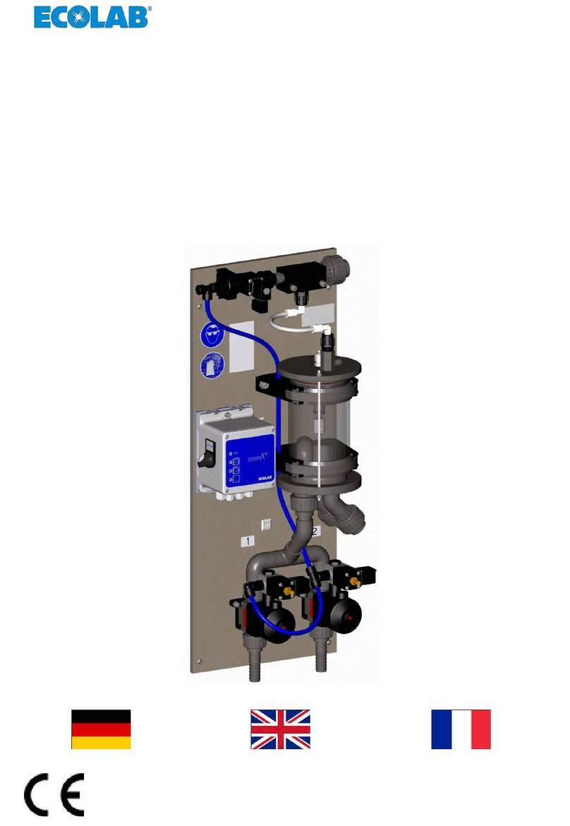
Ecolab Formula1 User manual

Installation & Operation Manual
Retain this manual for installation, operation,
programming, and servicing information.
This manual is intended for dispenser 9259-1069 (not 9259-1051).
1
Form 36922/0401/0525 Copyright Ecolab Inc. 2006 9259-2201

This page intentionally left blank
2

Table of Content
1. Introduction................................................................................................................... 5
1.1. Preface............................................................................................................... 5
1.2. System Features................................................................................................ 5
1.3. System Description and Packing List............................................................... 6
1.4. Principle of Operation....................................................................................... 8
2. Specifications.............................................................................................................. 10
2.1. Controller/Dispensing Unit............................................................................. 10
2.2. User and Machine Interface Modules............................................................. 11
2.3. Auxiliary Pump Cabinet – Optional ............................................................... 11
2.4. Installation Requirements ............................................................................... 12
3. System Installation...................................................................................................... 13
3.1. Preplanning..................................................................................................... 13
3.2. Accessories & Optional Parts List.................................................................. 14
3.3. Dispenser/Controller Installation.................................................................... 14
3.4. Installation Plumbing...................................................................................... 16
3.5. User and Machine Interface Module Installation............................................ 21
3.6. Power Up ........................................................................................................ 26
3.7. Dock Product Capsule..................................................................................... 26
3.8. Prime Product Delivery Tubes........................................................................ 26
3.9. Calibrate Dispenser......................................................................................... 27
3.10. Program Formula Amounts............................................................................. 27
3.11. Verify Delivery Amounts ............................................................................... 27
4. Programming............................................................................................................... 28
4.1. General Information........................................................................................ 28
4.2. Program Mode ................................................................................................ 30
4.3. QUICKSTART (See Figure 4.4) .................................................................... 33
4.4. ACCT SETUP (See Figure 4.5)...................................................................... 35
4.5. WASHER SETUP (See Figure 4.6)................................................................ 37
4.6. FORMULA PROG (See Figure 4.7) .............................................................. 40
4.7. RECORDS (See Figure 4.8)........................................................................... 42
4.8. PRIME MODE (See Figure 4.9)..................................................................... 44
4.9. TIME CALIB (See Figure 4.10)..................................................................... 47
4.10. DIAGNOSTIC (See Figure 4.11)................................................................... 50
4.11. Exit Programming........................................................................................... 51
5. Account Features ........................................................................................................ 52
5.1. Replacing Product Capsule............................................................................. 52
5.2. Selecting Formula........................................................................................... 52
5.3. Controller Access............................................................................................ 52
6. Set-Up and Operation ................................................................................................. 54
6.1. Product/Wash Signal Check ........................................................................... 54
6.2. Dispensed Quantity Check.............................................................................. 54
7. Troubleshooting.......................................................................................................... 55
8. Replacement Parts....................................................................................................... 60
8.1. Pump Tray....................................................................................................... 61
3

8.2. Water Valve.................................................................................................... 61
8.3. Electrical Parts................................................................................................ 62
8.4. Electrical Part Numbers.................................................................................. 63
8.5. Other Dispenser Components......................................................................... 63
8.6. Auxiliary Pump Components.......................................................................... 65
9. Maintenance................................................................................................................ 66
10. Appendix..................................................................................................................... 67
10.1. Pump Access................................................................................................... 67
10.2. Plumbing Schematic ....................................................................................... 67
10.3. Formula 1 Dispenser – Internal Construction................................................. 68
10.4. Labels and Overlays........................................................................................ 69
10.5. Programming Flow Chart ............................................................................... 70
4

1. Introduction
1.1. Preface
Formula 1 is the single-step laundry solution for on-premise laundry customers. The Formula 1 system comes
equipped with one main pump and three delivery valves to service up to three washers. The system
automatically makes a use-solution from a concentrated Formula 1 product. This use-solution is then delivered
to the washers automatically as requested. Formula 1 is an all-in-one formula; however, the system has an
optional pump cabinet for delivering a liquid product or sanitizer if desired.
The Formula 1 dispenser is for use with Formula 1 products ONLY!
Other chemicals must be added via an auxiliary pump.
1.2. System Features
•Serves 3 washers from 25 – 990 lbs rating each
Up to 5 Independent and programmable formulas per washer•
•Formula numbers can be matched to washer formula numbers for ease of training and use
•
y product
tion)
r proper capsule replacement
tart and stop length – No add on equipment
•Maximum Formula 1 Dose = 999 fl oz
•Maximum Auxiliary Product Dose = 33.3 fl oz
•Slide Out Pump Tray for Easy Service Access
•High Mount Product Drain Plug
•Load counter & capsule log
•Low voltage washer connections
•Pump and filter run time counters
Visual & audible low product alarm
•Concentrated product (Formula 1 product)
Plus optional product with Auxiliary Pump
•Programmable delays for Formula 1 and Auxiliar
•Universal washer signal input with indicator lights
•Automatic solution mixing (recircula
•Icon-based display for ease of training and use
•Digital user interface for ease of program selection
•Wheels for easy roll in installation
•Automatic Lid Latch to prompt users fo
•Chart Stop Integral with programmable delay s
required
•Dose Scaling for Washer Size – Automatic
5

Notes:
The dispenser is supplied with two communications
cables (one 14 ft. and one 25 ft.).
Only two Washer Interface Modules are supplied with the Formula 1 dispenser. If you plan to hook
up to three washers, you will need to order an additional Washer Interface Module AND an additional
communication cable (See Section 1.4 for Part Numbers)
1.3. System Description and Packing List
The Formula 1 System consists of several individual components designed to work
together to provide a safe, simple and reliable dispensing solution for On Premises
Laundry applications. The packaged system includes and is shipped with (See fig 1.1
through 1.4 for illustrations and details):
1. Formula One Dispenser
2. Two (2) Washer Interface Modules – Include Formula number and name labels
3. 14’ and 25’ communications cables
4. Auxiliary Pump Adapter cable
5. 80’ of 1/2 “ OD poly tubing for product delivery
6. 5’ of hose for the overflow to drain connection
7. Two (2) 15’ water hoses for Hot and Cold Water Connections
8. Vacuum Breaker assembly with pressure gauge
9259-1069 Formula 1 Dispenser Boxed and Un-Boxed
Fig 1.1
6

Item Part Number Description
1 9259-1075 Washer Interface Module
2 9259-2226 Communications Cable, 25 ft
3 9259-2222 Cable, Auxiliary Pump Adapter
4 9259-2225 Cable, communications, 14 ft
5 8524-2501 Vacuum Breaker
6 8539-0079 Pressure Gauge
7 8501-5026 Tubing, ½ in OD Poly (80 ft)
8 9482-2186 Water Hoses 15 ft (2 provided)
9 8501-6046 Drain Hose 5 ft
5 6
2
1
7
9
8
4
10
3
1
2
Fig 1.3
1
1
13
1
4
Fig 1.4
Fig 1.2
7

10 Miscellaneous Parts
N/S 8579-3032 Hose Y w/out shutoff valves (Qty 2)
N/S 8730-1032 Hose Clamp 11/16 to 1-1/4 SST
N/S 8524-4391 Check valve (Qty 3)
N/S 8730-1149 Hose Clamp 7/32” to 5/8” SST (Qty 6)
N/S 8561-5565 Union Connector ½ Push in (Qty 3)
N/S 9265-3303 32oz Spray Bottle
11 9259-1075 Washer Interface Module (2 Provided)
12 9259-2220 Formula Number Labels
13 9259-2221 Bi-Lingual Formula Name Labels
14 8999-2201 Dual Lock Tape
Fig 1.4 Continued
1.4. Principle of Operation
1. Overview
The Formula 1 System includes a combination controller/dispensing unit that is capable of feeding
up to three washers. The system uses a washer interface and user interface combination (together
referred to as a Washer Interface Module) at each washer and offers an optional auxiliary pump
cabinet for one liquid product. The “Controller” in the dispenser, is connected to the “Washer
Interface Module” at the Washer via “Communications Cables”. The Washer Interface Module
automatically adjusts for supply signal voltages ranging from 24 to 240VAC or 22 to 24VDC and
communicates the “supply signal” from the washer to the dispenser. Once a signal is received, the
Formula 1 System will pump products based on formula selection (at the User Interface portion
of the Washer Interface Module) and the associated dispenser programming.
The Formula 1 product is packed in a safe, convenient “capsule”. Upon removing the cap from the
capsule, placing it in the dock and initiating an evacuation sequence (see section 3.6 for details
of the procedure), the entire contents are sprayed out of the capsule and the dispenser reservoir
is filled with a use solution.
2. Capsule Evacuation (Refer to fig 11.2 Plumbing Schematic)
At the beginning of the capsule evacuation “spray out “cycle, the dispenser controller turns on the
hot water valve allowing hot water, from the facility, to pass through the dispenser’s water valve,
through the integrated flow control, (to control the amount of water delivered through the system)
through the atmospheric vacuum breaker and pressure gauge and on through the nozzle located
in the bottom of the dock.
After two minutes of hot water spray, the controller turns the hot water off and turns on the cold
water from the facility and routes the water through the same valve and flow control system
through to the nozzle. The cold water spray is for one minute.
Note: The ratio of hot water to cold water on time is selectable through the
programming menus. See Section 4.10 and fig. 4.11 for details.
The hot spray followed by a cold spray sequence is repeated for four cycles by the controller. As
the reservoir is filling a float switch mounted on the rear reservoir wall (low float) will close and
signal the controller to start recirculating the solution through the delivery pump and distribution
valve manifold and routed through a tank mix eductor to thoroughly mix the solution into a
homogonous mixture. Each time a new capsule is docked, the tank will recirculate for thirty
minutes. At every hour, on the hour, the controller will initiate the same recirculation sequence for
five minutes to keep the solution mixed.
8

After the four hot water/cold water cycles, the controller then continues to fill the reservoir with cold
water sprayed through the nozzle until the solution level closes a second float switch (high float)
mounted on the back wall of the reservoir. The cold water flow continues for four more minutes
after the high float switch closes.
Each capsule produces a use solution of approximately 9.5 gallons. If there is demand for the
Formula 1 product from the washers via the Washer Interface Module, the controller will deliver
the programmed volume of product to the required washer. Until the next capsule is docked and
evacuated, every hour, on the hour, the tank will be recirculated to keep the solution mixed.
The controller continuously monitors the float switches for product level. It is possible through the
programming menus to check the product level. If the product is at or above the high float, the
level will be reported as “HIGH”, if the level is at or below the below the low float, the level will be
reported as “LOW”. If the level is anywhere between “LOW” and “HIGH” the level will be reported
as “MID”. If the low float is open and the high float is closed the controller will display “????” for
level as an indication of an error.
As the dispenser responds to demand from any of the washers, the reservoir level will drop until
the low float switch opens. When the low float switch opens, the controller will turn on the “TANK
EMPTY” light and the audible alarm. The lid latch will unlock the lid and the lid will spring open.
All of these actions indicate that he capsule should be replaced and the capsule evacuation
sequence initiated. If product dosing continues for 90 seconds of cumulative pump run time
beyond low level, without capsule replacement, the dispenser will be in Lock Out mode. At this
point, the dispenser will ignore washer signals for product until a new capsule is docked and spray
out initiated. In the diagnostic menu, tank level will display “LOCK.”
The Formula 1 product can be programmed for amounts up to 999 ounces (29544 milliliters).
Liquid products (added via the auxiliary pump) are pumped directly from their shipping containers
to the washers. Each product injection may be delayed up to 999 seconds. Liquid products can be
programmed for amounts up to 33.3 ounces (985 milliliters). Up to 5 formulas may be programmed
for each washer. Chart Stop output wiring connections are available at the Washer Interface.
9

2. Specifications
2.1. Controller/Dispensing Unit
H
D
Figure 2.1
1/4 turn
fastener 1/4 turn
fastener
W
2.1.1. Dimensions
Height …………………………………………. 36.5 inches (927.1 mm)
Width ………………………………………….. 19.9 inches (505.5 mm)
Depth ………………………………………….. 24.1 inches (612.1 mm)
Weight …………………………………………. 76.0 lbs. (34.5 Kg)
Power ………………………………………….. 120 VAC, 60HZ, 3A
(GFI circuit recommended)
Washers ……………………………………….. 3 Maximum
Communications Cable …………………….… One 14’ and One 25’ cables supplied
Pump
Lift & Run …………………………………… 10’ lift max; 50’ run max
Pump Flow Rate …………………………… 1 GPM (approximately)
2.1.2. Service Access
The dispenser unit includes a controller and pump housing. The controller electronics are
accessible through a keyed-access plate to the right of the controller face plate. The
plumbing and water supply can be accessed on the back of the unit. The pump and product
diverter valve assembly are accessible by rotating the two 1/4 turn fasteners on the face of
the pump tray and pulling out the pump tray (see Figure 2.1).
10

2.2. User and Machine Interface Modules
User
Interface
Fig 2.2 Washer Interface
Module
Washer
Interface
2.2.1. Dimensions
User Interface
•Height…………………… 4.5" (114.3 mm)
•Width …………………… 3.5" (88.9 mm)
•Depth…………………… 2.2" (55.9 mm)
Weight………………… 0.8 lb (0.36 kg)
Depth…………………… 2.2" (55.9 mm)
•
2.3
Refer to the auxiliary pump Instruction Sheet 9259-2095 for specifications.
•
Machine Signal Interface
•Height…………………… 6.7" (170.2 mm)
•Width …………………… 4.8" (121.9 mm)
•
Weight………………… 2.0 lb (0.9 kg)
. Auxiliary Pump Cabinet – Optional
11

2.4. Installation Requirements
2.4.1. Water Supply
•Both hot and cold, min 15 psig dynamic @ pressure gauge.
3/4” male garden hose connections.
•
•Hot water temperature – minimum 100°F, maximum 145°F.
NOTE: ater >145°F, will require a tempering valve kit
art # 9259-1043).
20VAC/60HZ, 3 Amps. A GFI circuit is recommended.
loor space of 30” W X 72”D X 54”H is required for dispenser access.
ispensing
unit is required. Drain proximity for overflow connection should be less than 5 ft.
Accounts with hot w
(P
2.4.2. Electrical
1
2.4.3. Floor Space
F
2.4.4. Drain
A floor drain or drain trench to accommodate dispenser overflow located near the d
12

3. System Installation
3.1. Preplanning
It is very important to ensure that all necessary equipment is available in order to complete the
Formula 1 installation. A few minutes of planning may save a considerable amount of time during
the installation. It is necessary to locate a suitable location for the dispenser. Important
considerations include:
•Dispenser size – the dispenser is approximately 20” wide, 25” deep and 36.5” tall. It is
important to leave clearance to provide easy access to the dispenser, including 1’ on top
of the dispenser, 3’ in front & 1’ behind the dispenser.
•Product delivery tubing should not be hung higher than 10 ft off the floor, and the distance
to the furthest washer should be less than 50 ft.
•Proximity to water sources (hot and cold) should be less than 15 ft.
•le
0 ft. cable may be
•
•
and on the floor for the extra product pail. The auxiliary pump should be installed
er. The auxiliary pump requires a separate 115 VAC
Othe re
uct will be used.
•capsules so that the account can start-up immediately.
with three washers, an additional Washer Interface Module must be ordered
Insta tio
Be certain to verify that product is re-circulating through the external strainer by priming
the system to a drain or catch bucket.
•These steps assure accurate calibration and reduce overall installation time.
•Mount the User Interface Module to facilitate convenient user operation.
•Proximity to power source (120V) should be less than 9 ft.
•Easy access for account personnel to change product capsules.
The communication cables that run between the dispenser and the user interface modu
at the washing machine are 14 ft. and 25 ft. long. If necessary, a 5
ordered separately. (See Section 3.2 for part number)
Drain proximity for overflow connection should be less than 5 ft.
If using the optional auxiliary pump, space must be available on the wall for mounting the
cabinet
less than 10 feet from the dispens
outlet.
r p planning notes:
•Verify that the correct tubing and tools are available.
•Order an auxiliary pump assembly, if a liquid prod
Stock product
•If installing
separately. (See section 3.2 for part numbers)
lla n notes:
•Unpack the system and inspect the dispenser prior to disconnecting any pre-existing
equipment.
•Connect to power and water supplies and verify correct operation.
•Dock the first capsule to allow time for capsule evacuation and tank fill.
•
13

3.2. Accessories & Optional Parts List
14’ Communication Cable ……….……………….. 9259-2225
25’ Communication Cable ……….……………….. 9259-2226
50’ Communication Cable ……….……………….. 9259-2227
Washer Interface Module ………….……………… 9259-1075 (only 2 included withdispenser)
Optional Auxiliary pump ……………..……………. 9259-1046 (if liquid product is to be used)
Tempering Valve Assembly …………….………… 9259-1043 (if hot water to dispenser exceeds 145°F)
3.3. Dispenser/Controller Installation
3.3.1. Dispenser Wiring
The Formula 1 dispenser requires 120 VAC to operate. The dispenser comes with a pre-
installed 9’ electrical cord that is ready to plug in. If a condition exists where the cord cannot
be used (i.e. distances greater than 9’) the following procedure should be used.
NOTE: If a condition exists where the cord cannot be used (i.e. distances greater
than 9’) a minimum of 14-ga. wire enclosed in conduit or Seal-Tite is
required. All local codes must be followed.
NOTE: It is not recommended to use power from a laundry machine to operate the
dispenser.
NOTE: This dispenser must remain powered constantly, do not use outlets that
can be shut off manually (GFI outlets are OK).
From inside the electrical cabinet:
1. Remove the existing BROWN and BLUE wires off of the terminal posts on the back of
the ON/OFF circuit breaker (BROWN is hot, BLUE is neutral).
2. Remove the GREEN wire with the YELLOW tracer from the ground lug (GREEN is
ground).
3. Remove the 9’ power cord from the dispenser electrical enclosure.
4. Field-wire a new HOT, NEUTRAL and GROUND wire within the electrical enclosure.
These MUST BE brought into the electrical enclosure in conduit or Seal-Tite.
5. Attach the HOT and NEUTRAL wires to the terminal posts on the back of the ON/OFF
circuit breaker. Use the same polarity as the cord installation. Brown is hot, blue is
neutral.
6. Attach the FIELD GROUND wire to the grounding lug located on the front of the
electrical enclosure (Next to On/Off Circuit Breaker).
14

HOT WIRE (BROWN)
CONNECTION TO
BREAKER
NEUTRAL WIRE (BLUE)
CONNECTION TO
BREAKER GROUND WIRE
(GREEN/YELLOW)
CONNECTION TO
CHASSIS GROUND STUD
15

3.4. Installation Plumbing
Formula 1 installation requires plumbing the overflow connection, attaching the vacuum
breaker bracket, connecting water sources (both cold and hot), and connecting the product
delivery tubes.
PRESSURE
GAUGE AND
VACUUM
BREAKER
HOT & COLD WATER
SUPPLY INLETS
WATER INLET FROM
VALVE
WATER
OUTLET TO
SPRAY
N
OZZLE
TANK ACCESS
PLATE
PRODUCT OVERFLOW
(PLUMB TO DRAIN)
EXTERNAL
STRAINER
RECIRCULATION LINE
FROM DISTRIBUTION
VALVE
TANK DRAIN
RESERVED FOR FUTURE
APPLICATIONS
TO USER INTERFACE
MODULE
TO AUXILIARY
PUMP
ADJUSTABLE
ALARM
POWER
SWITCH
AC POWER
CORD
COLDHOT
MACHINE 2
OUTLET
MACHINE 1
OUTLET MACHINE 3
RETURN LINE FROM
STRAINER TO TANK
OUTLET
16
Figure 3.2

3.4.1. Plumbing the Overflow Connection
An overflow outlet for the dispenser’s tank is provided to direct the solution to a drain should
the tank level sensors or water solenoid fail. The overflow outlet (blue hose barb) is located
on the back of dispenser. A length of 5/8” tubing (as provided with dispenser) must be
connected to the outlet and routed to a floor drain.
Figure 3.3
1. Measure the distance from the overflow fitting to the floor drain and cut your 5/8” PVC
tubing to the desired length.
2. Connect the 5/8” PVC tube to the tank overflow outlet (blue drain tube) located on the
back of this dispenser (see Figure 3.3).
3. Secure the connection with a hose clamp.
4. Route the opposite end of the PVC tubing to a floor drain or drain trench.
5. If possible, try to secure the end of the PVC tube to the floor drain with a cable tie.
This prevents the hose from being “kicked around”.
NOTE: If a drain is unavailable, use an empty five-gallon pail.
17

3.4.2. Attaching the Vacuum Breaker
Attach the vacuum breaker bracket to the electrical enclosure, using the two supplied #8-32
screws (factory-installed at the mounting location). (See Figures 3.3, 3.4, and 3.5.)
Insert the inlet tube (originating from the base of the dispenser) into the inlet (lower) fitting on
the vacuum breaker. See figures 3.6 and 3.7.
NOTE: Make sure that all tubes are fully seated into fittings and that threads (if
present) are aligned (NOT cross threaded) and that all tube inserts are in
place.
Insert the outlet tube (factory inserted in the vacuum breaker outlet) into the upper elbow
fitting (to main spray nozzle) on the rear of the dispenser (refer to Figure 3.8).
Figure 3.3 Figure 3.4 Figure 3.5
Figure 3.6 Figure 3.7
Figure 3.8
18

3.4.3. Connecting Water Supplies
The dispenser automatically alternates between hot and cold water during the fill cycle. Hot
water >145°F can cause separation of the detergent use-solution and can adversely affect
the enzymes contained in some Formula 1 products. For installations with hot water in
excess of 145°F, a tempering valve kit (P/N 9259-1043) must be ordered. The following
instructions assume hot water temperature <145°F.
1. Use the ‘Y’ hose-connectors (if necessary) to provide hot and cold water sources for
the dispenser.
2. Route one of the provided 15’ hoses from the hot water source to the hot water swivel
fitting (see Figure 3-9).
3. Route one of the provided 15’ hoses from the cold water source to the cold water
swivel fitting (see Figure 3-9).
4. Turn on water and check for leaks.
WARNING – DO NOT OVERTIGHTEN BRASS SWIVEL COUPLING TO
PLASTIC NIPPLE!
To save time, you should now dock a product capsule and initiate dissolution.
Remaining installation procedures can be performed while the tank is filling.
Refer to Sections 3.6 – 3.7, POWER UP
Figure 3.9
Connect
hot water
hose
Connect
cold
water
19

3.4.4. Connecting the Product-Delivery Tubes
A 1/2” OD (3/8” ID) polyethylene tube (P/N 8501-5139) is used to deliver the detergent to
each laundry machine. It is important that the outlet tubing DOES NOT exceed 50’ (15
meters) under normal installation.
1. Locate the three 1/2” tubes on the back of the dispenser (see Figure 3-10). The tube
for laundry machine #1 is located on the left, washing machine #2 is in the middle and
machine #3 is on the right (as viewed from behind).
2. Connect 1/2” PE tubing to discharge tubes (mentioned above) using the 1/2” union
connector located in the installation kit. A plug was put on the line for machine #3 at
the factory. This is done to prevent leaking from this line in accounts with only two
washers.
3. Remove the plug from the tube for Washer #3, if connecting to a third washer
Note: Tubes must be inserted ~0.75” for proper engagement. Tubes not being
connected to washers should be plugged with provided coupling and plug.
Do not shorten tubes!
Washer #1 Washer #2 Washer #3
Figure 3.10
4. Route the 1/2” OD PE tube from the dispenser to each corresponding laundry
machine (it will be helpful to label each tube with its washer number). Note: Leave 2’-
3’ of extra length to allow the dispenser to be moved or the pump tray to be pulled
out.
5. Install a check valve (included in the install kit) for each washing machine. This valve
is vital for accurate and consistent product dispensing. This check valve should be
installed in the line 1 to 2 inches from the injection port. IMPORTANT: ensure that
the arrow on the check valve is pointing towards the injection port (the direction that
fluid will be flowing). If the check valve is installed backwards, product will not flow to
the laundry machine.
6. Secure the tubing at the injection port of each laundry machine.
7. Anchor the tubing to the wall or rigid piping to provide strain relief and to keep the
installation looking neat and clean.
20
Other manuals for Formula1
1
Table of contents
Other Ecolab Water System manuals
Popular Water System manuals by other brands

Oase
Oase Water Quintet Creative operating instructions
BIO-MICROBICS
BIO-MICROBICS MicroFAST 4.5 installation manual

MELAG
MELAG MELAdest 65 user manual
Culligan
Culligan Aqua-Cleer Good Water Machine owner's guide
BWT
BWT AQA smart Installation and operating manual

Tollco
Tollco WaterFuse Apartment User's manual & installation instructions
