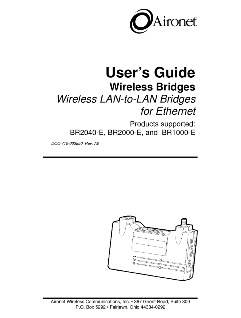
Aironet BRE100 User manual

Aironet Wireless Communications, Inc. • 3875 Embassy Parkway
Akron, Ohio 44333-8357
www.aironet.com
User’s Guide
High Performance Wireless
Bridge Solutions
for Ethernet andToken Ring
Products supported:
BRE100 and BRE500 Series (ETSI Compliant) and
BR100 and BR500 Series (North American)
DOC-710-004496-B0

AironetWireless Communications, Inc.
No part of this document may be reproduced or transmitted in any means, elec-
tronic or mechanical, for any purpose, without the written permission of Aironet.
Information in this document is subject to change without notice. Aironet makes
no representation or warranties with respect to the contents of this manual and
specifically disclaims any express or implied warranties of merchantability or
fitness for any particular purpose.
© 1998 Aironet Wireless Communications, Inc.
All rights reserved.
BRE101
TM
, BRE105
TM
, BRE110
TM
, BRE501
TM
, BRE520
TM
, BRE530
TM
, BR100
TM
,
BR110
TM
, BR120
TM
, BR130
TM
, BR500
TM
, BR510
TM
, BR520
TM
, BR530
TM
, and
Aironet
TM
are trademarks of Aironet Wireless Communications, Inc.
Other trademarks used are properties of their respective owners.
Printed in USA
DOC-710-004496-B0

Table of Contents
Introduction ........................................................ 1-1
Purpose of the Manual .................................. 1-1
Safety Information ......................................... 1-2
Snap-On Antenna ................................... 1-3
High Antennas ........................................ 1-3
Warning for Laptop User ........................ 1-3
Antenna Options ........................................... 1-4
Before You Start ............................................ 1-5
Determining Bridge Location ......................... 1-5
Building to Building Connectivity ............ 1-6
Line of Site .............................................. 1-6
Terminology .................................................. 1-8
Installation .......................................................... 2-1
Installing the Antenna .................................... 2-1
Installing the Console Port Cable .................. 2-3
Installing the Ethernet Connection ................ 2-4
Installing the Token Ring Connection ........... 2-6
Attaching the AC/DC Power Pack and
Powering On Ethernet or Token Ring
Wireless Bridge ............................................. 2-7
Viewing the Indicator Displays ...................... 2-8
Top Panel Indicators ............................... 2-8
Back Panel Indicators (Ethernet Only) .. 2-10
Configuration ..................................................... 3-1
Accessing the Console System ..................... 3-1
Configuring the Wireless Bridge .................... 3-2
SSID Identifier (SSID) ............................. 3-2
Assigning an IP Address ........................ 3-3
Verifying Association .............................. 3-3

Appendix A .........................................................A-1
System Configurations ..................................A-1
Point-to-Point Wireless Bridge ................A-2
Supporting Mixed Network Topologies .........A-3
Point-to-Multipoint Wireless Bridge ........A-5
Infrastructure Extension with Repeaters..A-7
Wireless Bridge with Wireless
End Nodes...............................................A-8
Appendix B..........................................................B-1
Manufacturers Federal Communication
Commission Declaration of Conformity
Statement.......................................................B-1
Department of Communications–Canada
Canadian Compliance Statement ..................B-5
European Telecommunications Standards
Institute Statement of Compliance
Information to User.........................................B-6
Appendix C .........................................................C-1
Technical Reference Manual ........................C-1
Communications ...........................................C-1
Web Site ........................................................C-1

Introduction
1-1
Introduction
Purpose of the Manual
The purpose of this User’s Guide is to allow you to easily
install and initially configure your Aironet Wireless Bridge.
Aironet Wireless Bridges enable you to connect two or
more Token Ring and/or Ethernet networks to create a
single virtual LAN.Workstations on each LAN can
communicate with each other through the Wireless Bridge
connection if they are on the same physical LAN.
When connecting two or more LANs, each LAN uses an
Aironet Wireless Bridge and an antenna to transmit and
receive information. Each RF based Wireless Bridge unit is
connected to the LAN. A Wireless Bridge appears as a
single network node on the wired LAN. It performs routing
functions by moving packets from the wireless LAN to
remote workstations on the radio network. Aironet Wireless
Bridges utilize Direct Sequence Spread Spectrum (DSSS)
technologies in the 2.4 GHz frequency band.
For detailed technical and configuration procedures, see
the Technical Reference Manual document number
710-004494.

Introduction
1-2
Safety Information
The FCC with its action in ET Docket 96-8 has adopted a
safety standard for human exposure to radiated frequency
(RF) electromagnetic energy emitted by FCC certified
equipment.The Aironet products meet the uncontrolled
environmental limits found in OET-65 and ANSI C95.1,
1991. Proper operation of this radio according to the
instructions found in this manual will result in the user
exposure to be substantially below the FCC recommended
limits.
• Do not touch or move antenna(s) while the unit is
transmitting or receiving.
• Do not hold any component containing the radio such
that the antenna is very close or touching any exposed
parts of the body, especially the face or eyes, while
transmitting.
• Do not operate a portable transmitter near unshielded
blasting caps or in an explosive environment unless it
is a type especially qualified for such use.
• Do not operate radio or attempt to transmit data unless
the antenna is connected, if not, the radio may be
damaged.
LISTED
UL
®
®

Introduction
1-3
Snap-On Antenna
Always orient antenna such that it is at least 5 cm
(2 inches) away from your body.
High Gain Antennas
High gain wall mount or mast mount antennas are
designed to be professionally installed and should be
located at a minimum distance of 30 cm (12 inches) or
more from your body. Please contact your professional
installer, VAR, or antenna manufacturer for proper
installation requirements.
Warning for Laptop User
In order to comply with the FCC RF exposure limits, it is
recommended when using a laptop with the snap-on
antenna, that the antenna should not be positioned
closer than 5 cm (2 inches) from your body or nearby
persons for extended periods of time while it is transmit-
ting (or operating).If the antenna is positioned less than
5 cm (2 inches) from the user, it is recommended that
the user limit exposure time or engage the power
saving features of the Aironet radio to reduce RF
exposure. See the Technical Reference Manual for
proper operation of power savings mode.

Introduction
1-4
Antenna Options
Aironet Bridge Solutions have been packaged to provide
wide area bridge connectivity in accordance with regulatory
rules and regulations. Aironet has designed the product
packages to provide optimal performance, measured by
throughput and range, while maintaining compliance with
various regulatory agencies around the world.
Approved antennas for use with each product are listed
below:
• BRE101, BRE501, BR110, and BR510
5.2 dBi Omni directional antenna*
6 dBi Patch antenna*
• BRE105, BRE505, BRE520, BR120, and BR520
12 dBi Omni directional antenna**
13.5 dBiYagi antenna**
• BRE110, BRE510, BRE530, BR130, and BR530
21 dBi parabolic dish antenna
* Can be used with the BRE105, BRE505, BRE520,
BRE110, BRE530, BR110, BR120, BR130, BR520,
and BR530 Series although range will be reduced.
** Can be used with the BRE110, BRE530, BR120
BR130, and BR530 Series although the maximum
range of the Bridge System will be reduced.
Aironet offers Bridge Packages and a variety of antenna
options to satisfy varying communication requirements
often dictated by premise considerations.

Introduction
1-5
BeforeYou Start
After unpacking the system, make sure the following items
are present and in good condition.
• Wireless Bridge (Ethernet or Token Ring model)
• Power Pack.The power pack will be either 120VAC/
60Hz or 90-264VAC/47-63Hz to 12-18VDC, whichever
is appropriate for country of use.
• Lightning Arrestor (Bridge Package option)
• Mounting Kit
• Low Loss Antenna Cable
• Appropriate Directional Antenna (Bridge Package
option)
If any item is damaged or missing, contact your Aironet
supplier. Save all shipping and packing material in order to
repack the unit should service be required.
Determining Bridge Location
Before beginning installation and configuration, determine
where you want the Aironet Wireless Bridge located.
Because the unit is a radio device, decisions must be made
regarding unit and antenna location to ensure optimum
radio range and throughput performance.

Introduction
1-6
Building to Building Connectivity
Radio ranges for building to building connections are
determined by antenna elevation, path clearances, and
line-of-site considerations.To maximize the range of
your building to building connections, the antenna
should be as high as possible.
Line of Site
A clear line of sight must be maintained between
Wireless Bridge antennas. Any obstructions may
impede the performance or prohibit the ability of the
Wireless Bridge to transmit and receive data.
Directional antennas should be placed at both ends at
appropriate elevation with maximum path clearance.
100 SeriesWireless Bridge (2 Mbps)
Bridge Range Antenna
BRE115 (ETSI)
BR110 1 Km
2 Miles 6 dBi patch
BRE120 (ETSI)
BR120 5 Km
7 Miles 13.5 dBiYagi antenna
BRE130 (ETSI)
BR130 10 Km
19 Miles 21 dBi parabolic dish

Introduction
1-7
500 SeriesWireless Bridge (11 Mbps)
Bridge Range Antenna
BRE515 (ETSI)
BR510 1 Km
1 Miles 6 dBi patch
BRE520 (ETSI)
BR520 2 Km
3 Miles 13.5 dBiYagi antenna
BRE530 (ETSI)
BR530 5 Km
8 Miles 21 dBi parabolic dish

Introduction
1-8
Terminology
When configuring your system, and when reading this
manual, keep in mind the following terminology:
Infrastructure
– The wireless infrastructure is the
communications system that combines Aironet Bridges,
mobile nodes and fixed nodes. Aironet Bridges within the
infrastructure can be either root units, which are physically
wired to the LAN backbone, or can act as wireless repeat-
ers.Other RF enabled devices serve as fixed nodes or
mobile nodes.
Root Unit
– The root unit is an Aironet Bridge that is
located at the top, or starting point, of a wireless infrastruc-
ture.The root unit provides the physical connection to the
wired LAN (such as Ethernet or Token Ring) and contains
configuration information in its association table that covers
all nodes in the infrastructure.
Repeater
– A repeater is an Aironet Bridge that extends the
radio range of the infrastructure.A repeater is not physically
attached to the wired LAN, but communicates via radio to
another Bridge, which is either a root unit or another
repeater.
End Node
– A radio node that is located at the end of the
Network Tree.

Introduction
1-9
Parent/Child Node
– Refers to the relationships between
nodes in the wireless infrastructure.The complete set of
relationships is sometimes described as a Network Tree.
For example, the Aironet Bridge (at the top of the tree)
would be the parent of the end nodes. Conversely, the end
nodes would be the children of the Aironet Bridge.
Association
– Each root unit or repeater in the
infrastructure contains an association table that controls
the routing of packets between the Bridge and the wireless
infrastructure.The association table maintains entries for
all the nodes situated below the Aironet Bridge on the
infrastructure including repeaters and radio nodes.

Introduction
1-10

Installation
2-1
Installation
This section describes the procedures for installing the
Aironet Wireless Bridge.
Installing the Antenna
Before installing your Bridge System, we recommend that
you test the Bridge using the 2.2 dBi dipole antenna
included in your package.Once testing is completed, install
your Wireless Bridge for use with the appropriate antenna
for your application using the following the instructions.
1. With the unit powered off, attach the lightning arrestor
to the antenna connector.
NOTE:The lightning arrestor is available in the Bridge
Package option or may be purchased separately.
STP UTP
Token Ring
Ethernet
10Base2 10Base5 10BaseT

Installation
2-2
2. Connect the lightning arrestor to one end of the low loss
antenna cable.
3. Connect the antenna to the other end of the low loss
antenna cable.Mount the Bridge antenna at an appro-
priate elevation to ensure maximum path clearance and
line of sight considerations.
NOTE: Do not over-tighten; finger tight is sufficient.
Position the antennas vertically for best omni-directional
signal reception.
NOTE:The lightning arrestor should be connected to the
antenna connector on the Wireless Bridge.The lightning
arrestor is added to provide surge protection to the Bridge
in the event of voltage surges as a result of a lightning
strike.
NOTE: Due to FCC and DOC Regulations, the antenna
connectors on the Aironet Bridge are of reverse polarity to
the standard TNC connectors.

Installation
2-3
Installing the Console Port Cable
1. Attach the Console Port cable to the serial port. Attach
the other cable end to the serial port on a terminal or a
PC running a terminal emulation program.Use a 9-pin
male to 9-pin female straight through cable.
2. Set the terminal to
9600
Baud,
No
-Parity,
8
data bits,
1
Stop bit, and ANSI compatible.
NOTE:This connection is required for setting up initial
configuration information. After configuration is
completed, this cable may be removed until additional
configuration is required via the serial port.

Installation
2-4
Installing the Ethernet Connection
The Aironet Wireless Ethernet Bridge supports three
connection types:
• 10Base2 (Thinnet)
• 10Base5 (Thicknet) AUI connector
• 10BaseT (Twisted Pair)
To Attach 10Base2 (Thinnet) Cabling:
1. Make sure the unit is powered off.
2. Attach the Thinnet cabling to each end of a BNC
T-connector, if applicable.
3. Attach the T-connector to the 10Base2 BNC. If the unit is at
the end of the Ethernet cable, a 50-Ohm terminator must be
installed on the open end of the T-connector.
NOTE: If you are installing a Token Ring Bridge,
proceed to page 2-6.
10Base2 10Base5 10BaseT
CAUTION: Removing a terminator to install extra cable, or
breaking an existing cable to install a T-connector, will
cause a disruption in Ethernet traffic.Consult with your LAN
administrator before you change any Ethernet cabling
connections.

Installation
2-5
To Attach the 10Base5 (Thicknet) Cabling:
1. Make sure the unit is powered off.
2. Attach the transceiver connector to the 10Base5 AUI
port.
3. Slide the locking mechanism in place.
4. Attach the other end of the transceiver drop cabling to
an external transceiver.
To Attach the 10BaseT (Twisted Pair) cabling:
1. Make sure the unit is powered off.
2. Plug the RJ-45 connector into the 10BaseT port
(Twisted Pair).
3. Connect the other end of theTwisted Pair cabling to the
LAN connection (such as a hub or concentrator).
10Base2 10Base5 10BaseT

Installation
2-6
Installing theToken Ring Connection
The Aironet Wireless Token Ring Bridge supports three
connection types:
• Shielded Twisted Pair (STP)
• Unshielded Twisted Pair (UTP)
To Attach the STP Cabling:
1. Make sure the unit is powered off.
2. Attach the transceiver connector to the DB-9 port.
3. Attach the other end of the transceiver drop cabling to a
Token Ring Multi-Station Access Unit (MAU).
To Attach the UTP Cabling:
1. Make sure the unit is powered off.
2. Plug the RJ-45 connector into the UTP port.
3. Connect the other end of the UTP cabling to a Token
Ring Multi-Station Access Unit (MAU).
STP UTP
STP UTP
This manual suits for next models
17
Table of contents
Other Aironet Network Router manuals
Popular Network Router manuals by other brands

D-Link
D-Link DSL-526E Quick installation guide

peplink
peplink Pepwave MAX 700 user manual

Asus
Asus RT-AX1800S quick start guide

Barracuda Networks
Barracuda Networks Link Balancer quick start guide

ZyXEL Communications
ZyXEL Communications ES-2024PWR Support notes

Korenix
Korenix JetNet 5428G Series user manual