ETIC IPL-3G-G-1400 User manual

IPL-3G
UMTS-GPRS-EDGE router
________________
INSTALLATION MANUAL
Document reference : 9019609-01
________________

CONTENT
SAFETY & CONFORMITY
1SAFETY RECOMMENDATIONS........................................................................ 3
2CERTICATE OF CONFORMITY......................................................................... 4
PRODUCT DESCRIPTION
1PRODUCT CHARACTERISTICS ....................................................................... 5
2DELIVERY CONTENT AND ACCESSORIES .................................................... 6
3PRODUCT OVERVIEW ...................................................................................... 7
4DIMENSIONS ..................................................................................................... 8
5CONNECTORS................................................................................................... 9
6LED INDICATORS............................................................................................ 12
7DIP SWITCHES ................................................................................................ 14
8FACTORY DEFAULT PUSH-BUTTON ............................................................ 14
9MOUNTING THE PRODUCT ON A DIN RAIL OR REMOVING IT................... 15
10 COOLING 16
11 RS232 INTERFACE.......................................................................................... 16
12 RS485 INTERFACE.......................................................................................... 17
13 DIGITAL INPUT AND OUTPUT........................................................................ 18
GETTING STARTED
1CONNECTING THE ANTENNA........................................................................ 19
2INSTALLING THE SIM CARD.......................................................................... 20
3CONNECTING THE PC TO THE HTML SERVER ........................................... 21
4SETTING UP THE UMTS CONNECTION ........................................................ 23
5FURTHER CONFIGURATION.......................................................................... 23

SAFETY & CONFORMITY
IPL-3G UMTS router Page 3
1 Safety recommendations
The IPL-3G is a low power radio transmission and reception device. It conforms to
rules imposed to UMTS or GSM-GPRS-EDGE terminals.
Check that using such a device is authorized at the location where you wish to
install it.
Do not use the IPL-3G router in locations with a potentially explosive atmosphere
like, for instance, petrol stations or areas where the atmosphere contains
chemicals or particles.
The IPL-3G uses the UMTS radio network and wireless waves. It is why, it is is not
possible to guarantee it will connect without interruption.
It is not possible to rely only the IPL-3G and the UMTS network to guarantee the
security of an automated system.

SAFETY & CONFORMITY
Page 4 IPL-3G UMTS router
2 CERTICATE OF CONFORMITY
The manufacturer, ETIC Telecom company – 13 chemin du vieux chêne – 38240 Meylan –
France Hereby declares that the listed products
Type of device : UMTS & GSM - GPRS – EDGE router
Models: IPL-3G router family
conforms to the Council Directive 1999/5/EC related to radio and telecommunication terminal
equipments.
The harmonized standards to which the equipment complies are :
Standard Title
EN301489-1 Electromagnetic compatibility and Radio spectrum Matters :
Part 1 : General requirements
EN301489-7
Electromagnetic compatibility and Radio spectrum Matters :
Part 7 : Specific conditions for mobile and portable radio and ancillary
equipment of digital cellular radio
EN61000-6-2
Ed. 2001
Immunity :
EN60100-4-2 Electrostatic Discharge
EN60100-4-3 Radiated Immunity
EN60100-4-4 EFT/Burst Immunity
EN60100-4-5 Surge Immunity
EN60100-4-6 Conducted Immunity
EN61000-6-4
Ed 2001
Emission :
EN55022 radiated and conducted emission
EN60950 Security
EN50385 Human exposure to radio frequency fields exposure
EN301511 Global System for mobile communication
Gilles Bénas
Quality manager
5th december 2011
PRODUCT DESCRIPTION
IPL-3G UMTS router Page 5
1 PRODUCT CHARACTERISTICS
IPL-3G-G-….. router
1400
1400B
1201
1201B
1220
1220B
1230
1230B
UMTS frequency 850 1900 / 2100 MHz
GSM-GPRS frequency 850 / 900 / 1800 / 1900 MHz
Min. supply voltage VDC 10 10 10 10 10 10 10 10
Max. supply voltage
VDC
60 60 60 60 30 30 60 60
Ethernet 10-100 BT 4 4 2 2 2 2 2 2
RS232 0 0 0 0 1 1 2 2
RS485 - 2 wires 0 0 0 0 1 1 0 0
IPL-3G-E-….. router
1400
1400B
1201
1201B
1220
1220B
1230
1230B
UMTS frequency 900 / 2100 MHz
GSM-GPRS frequency 900 / 2100 MHz
Min. supply voltage VDC 10 10 10 10 10 10 10 10
Max. supply voltage
VDC
60 60 60 60 30 30 60 60
Ethernet 10-100 BT 4 4 2 2 2 2 2 2
RS232 0 0 0 0 1 1 2 2
RS485 - 2 wires 0 0 0 0 1 1 0 0
PRODUCT DESCRIPTION
Page 6 IPL-3G UMTS router
2 Delivery content and accessories
The product itself is delivered with a CD including the user manual in English and
the eticfinder software tool with which you can discover the IP address of any
product manufactured by ETIC TELECOM and connected to an Ethernet network.
Accessories to order separately reference
90 ° antenna ANT210
Magnet mount antenna (cable length 2,5 m) ANT211
Roof mount antenna (cable length 1,5 m) ANT212
RS232 9 Male connector CAB592
RS232 9 Female connector CAB593
Surge protection PS02-1
PRODUCT DESCRIPTION
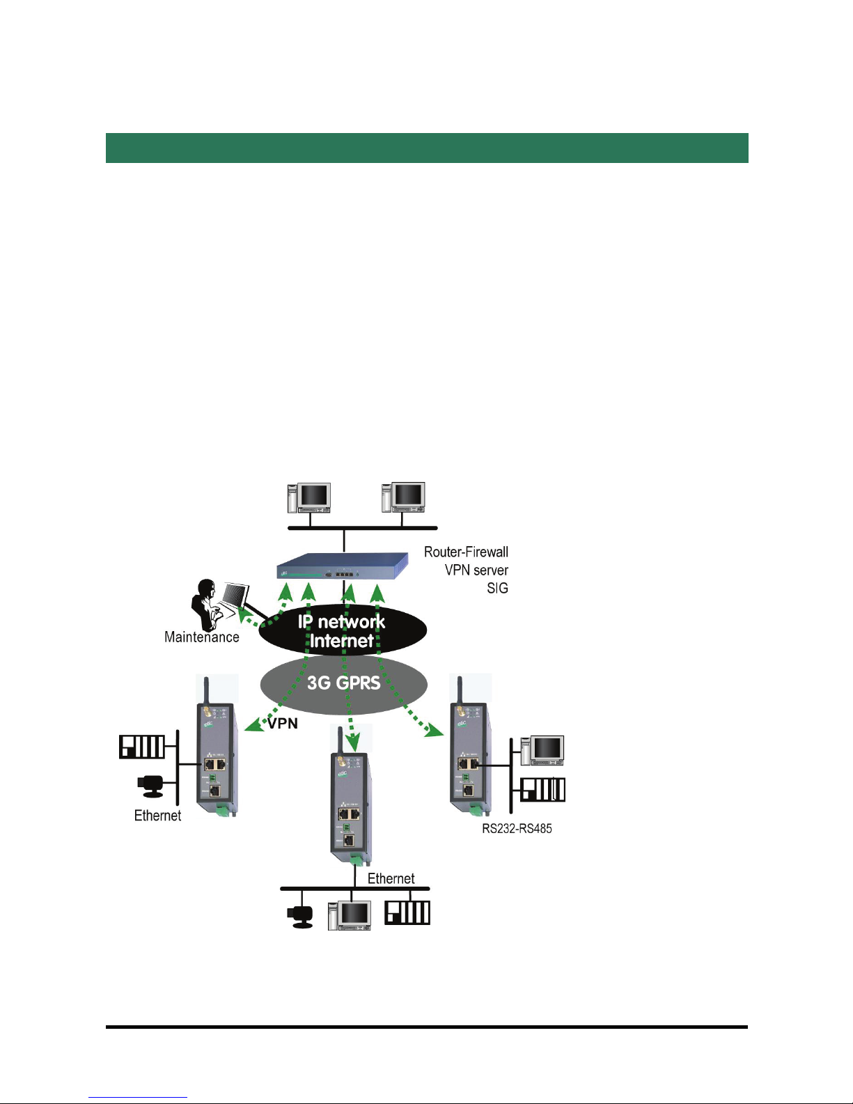
3 Product overview
The IPL- 3G router is designed to interconnect safely automated devices over the
UMTS 3G or the GPRS-EDGE service.
The connection is permanent.
The IPL-3G provides to authorized users a remote access to the devices
connected either using a fixed IP address or the DynDNS service or the
M2Me_Connect service provided by ETIC TELECOM.
The product includes an up-to-date RS to IP gateway, enabling to connect serial
devices safely to the 3G network and the Internet.
IPL-3G UMTS router Page 7
PRODUCT DESCRIPTION
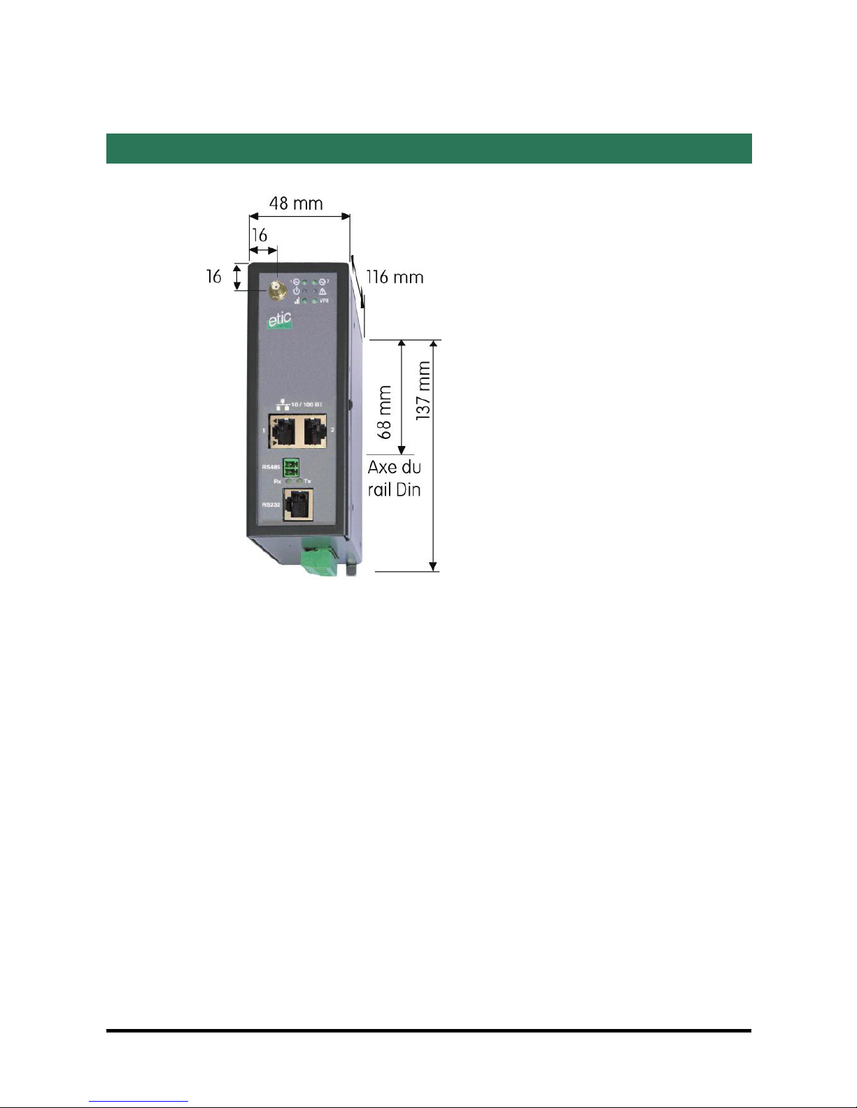
4 Dimensions
Page 8 IPL-3G UMTS router
PRODUCT DESCRIPTION
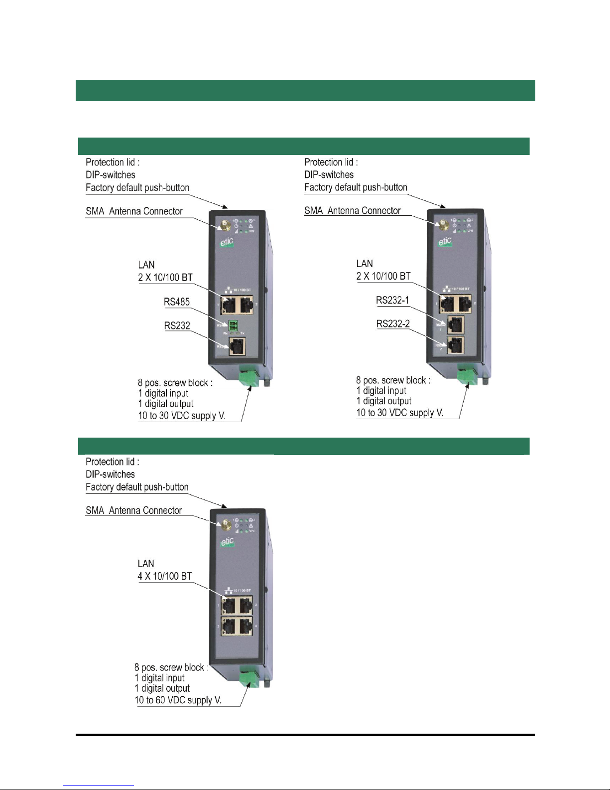
5 Connectors
X = G or E (see the product identification table on page 5).
IPL-3G-X-1220 IPL-3G-X-1230
IPL-3G-X-1230
IPL-3G UMTS router Page 9
PRODUCT DESCRIPTION
Page 10 IPL-3G UMTS router
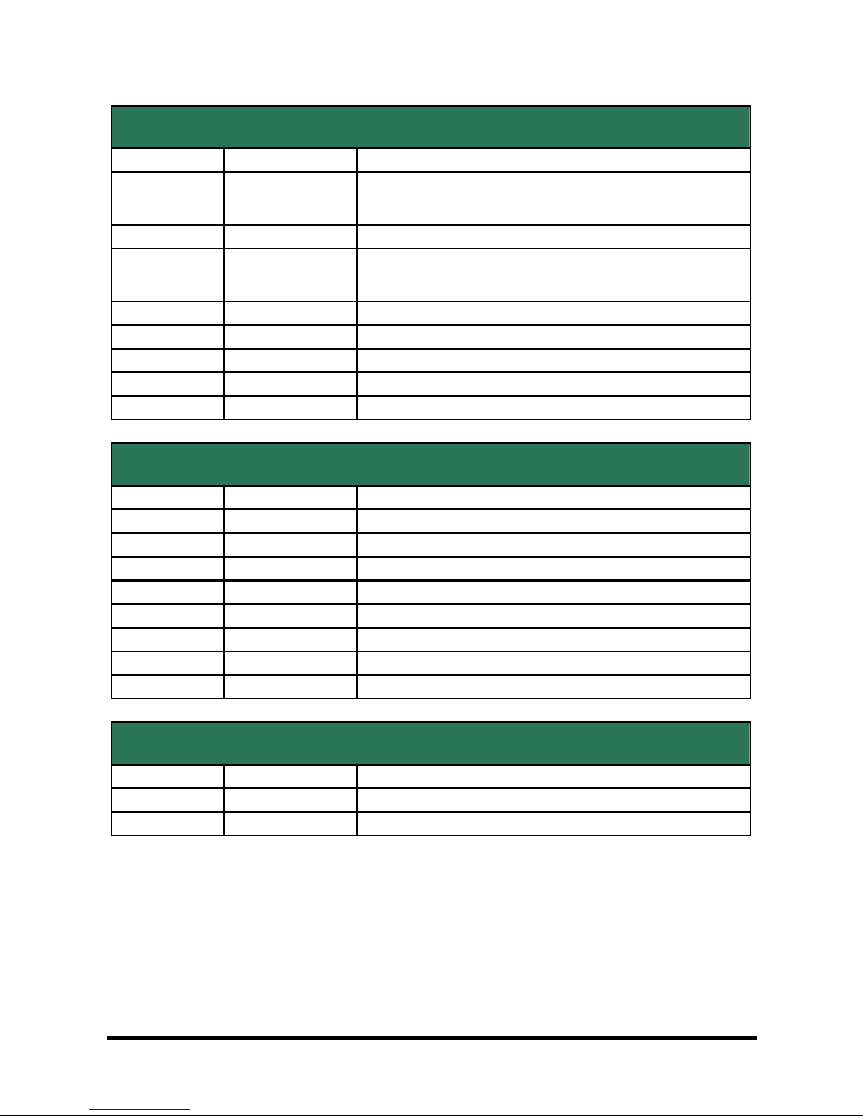
8 positions screw terminal : Supply voltage and digital input / output
Position Name Description
1 Power 1 + IPL-3G-X-1220 or IPL-3G-X-1220-B : 10 to 30 VDC
All other models : 10 to 60 VDC
2 Power 1 - GND
3 Power 2 + IPL-3G-X-1220 or IPL-3G-X-1220-B : 10 to 30 VDC
All other models : 10 to 60 VDC
4 Power 2 - GND
5 3V3 3 V DC provided by the IPL router
6 In Digital input
7 F + Digital output + (max 50Vdc - 0,6A)
8 F - Digital output -
RJ45 connector : Ethernet
Position Name Description
1 Tx + Emission polarity +
2 Tx - Emission polarity -
3 Rx + Reception polarity +
4 N.C -
5 N.C -
6 Rx - Reception polarity -
7 N.C. -
8 N.C. -
RS485 screw terminal
Position Name Description
1 A RS485 polarity A
2 B RS485 polarity B

PRODUCT DESCRIPTION
IPL-3G UMTS router Page 11
RS232 RJ45 connector port 1
(To connect to a DCE to the RS232 port)
Position Circuit Function
1 DTR - 108 OUT Data terminal ready
2 TD - 103 OUT Data Emission
3 RD - 104 IN Data Reception
4 DSR - 107 IN Data set ready
5 SG - 102 - Ground
6 Not used OUT -
7 CTS - 106 IN Clear to send
8 RTS - 105 OUT Request to send
RS232 RJ45 connector port 2
(To connect to a DCE to the RS232 port)
Position Circuit Function
1 Not used
2 TD - 103 OUT Data Emission
3 RD - 104 IN Data Reception
4 Not used
5 SG - 102 - Ground
6 Not used
7 Not used
8 Not used
PRODUCT DESCRIPTION
6 Led indicators
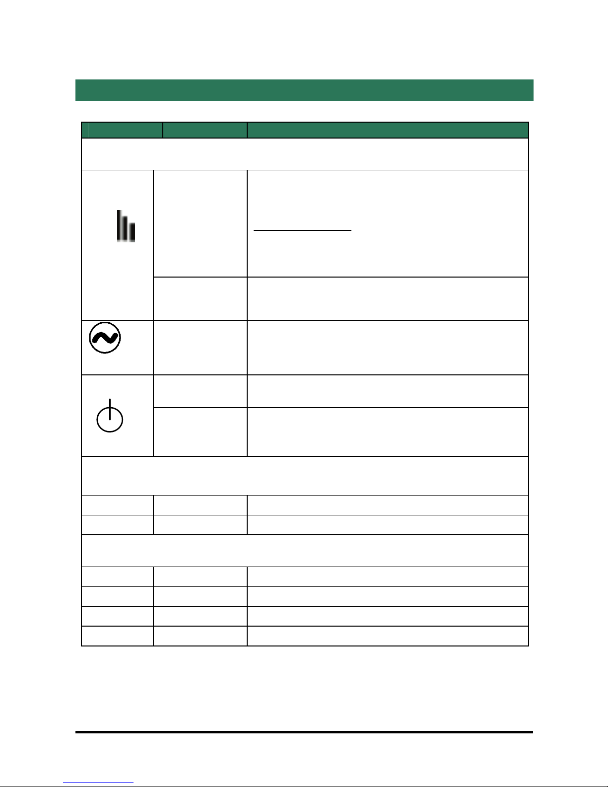
Indicator Status Description
All models
Flashing green
After power-on
After power-on, and until the connection to the 3G
network, the reception signal strength is indicated by
the number of flashes.
See the table below.
Remark : The diagnostic menu reports the precise value
of the reception signal.
Line /
Lit Green The router is connected to the 3G network.
Lit Green The supply voltage is present
Green The unit is ready
Red
The product is starting
The SIM card is not present
The 3G modem is in failure
IPL-3G-X-1220 & IPL-3G-X-1220-B (with 1 RS232 and 1 RS485 interface)
Rx Flashing green Bytes received from the RS232 or RS485 (to IPL)
Tx Flashing green Bytes transmitted to the RS22 or RS485 (from IPL)
IPL-3G-X-1230 & IPL-3G-X-1230-B (with 2 RS232 interfaces)
Rx Flashing green Bytes received from the RS232 –1 interface (to IPL)
Tx Flashing green Bytes transmitted to the RS22 –1 interface (from IPL)
Rx Flashing green Bytes received from the RS232 –2 interface (to IPL)
Tx Flashing green Bytes transmitted to the RS22 –2 interface (from IPL)
Page 12 IPL-3G UMTS router

PRODUCT DESCRIPTION
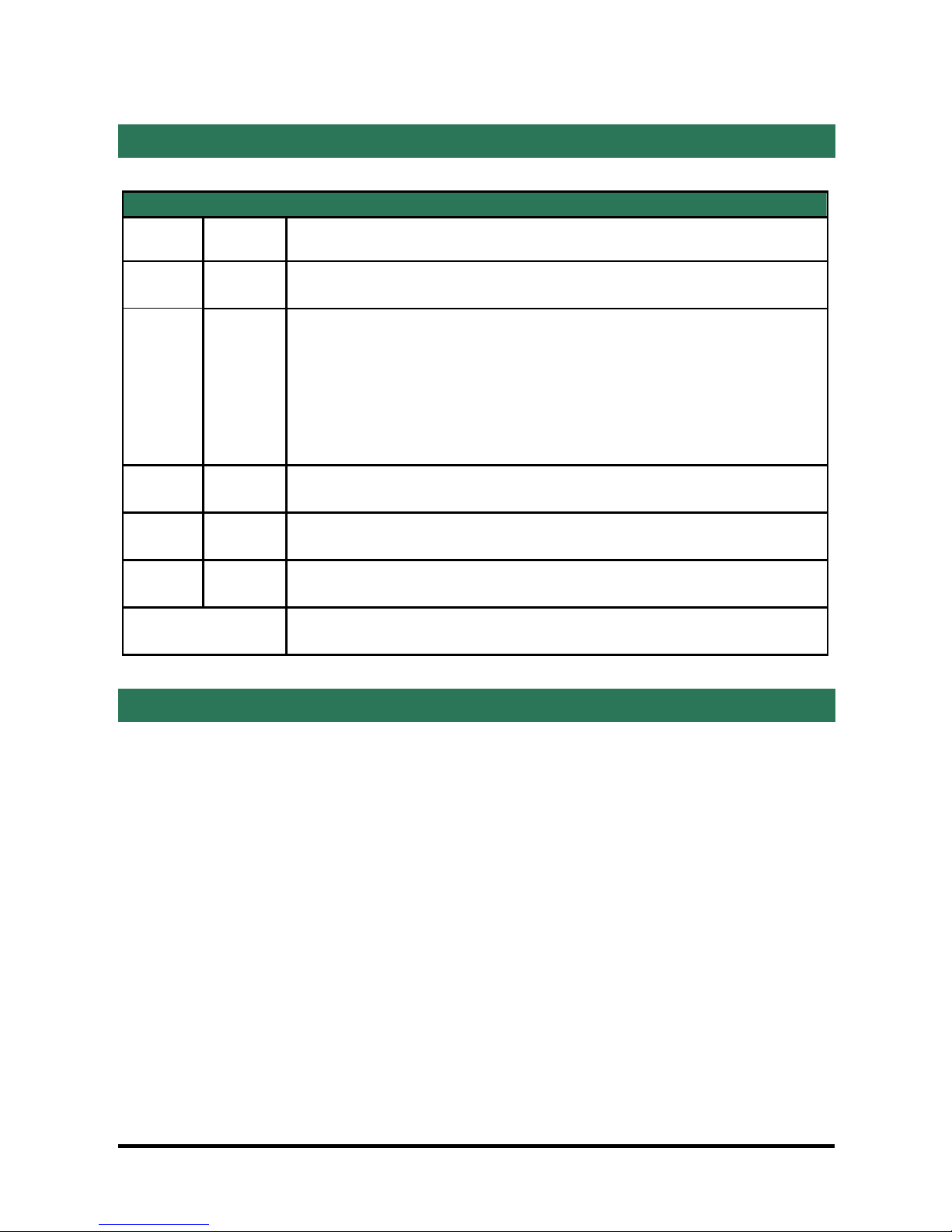
RF reception signal strength indicator
Description Status
RF Reception dBm
(Diagnostic menu)
3 flashes Good reception
-50 to - 80
2 flashes Sufficient reception
The level of the reception signal is
acceptable.
However, some error may occur and the
data rate might be lower.
-81 to –90
1 flash Insufficient reception
The level of the reception signal is weak ;
errors and disconnection might occur.
The reception conditions must be improved
to get a reliable connection
-91 to -110
Always OFF No reception
Control or replace the antenna or the
product itself.
Can a communication be set with a mobile
phone ?
< -111
Always ON The router is now connected to the 3G-GSM
network
IPL-3G UMTS router Page 13
PRODUCT DESCRIPTION
Page 14 IPL-3G UMTS router
7 DIP switches
DIP switches
SW 1 SW 2 Management
OFF OFF The current IP@ of the product is the stored IP @
ON OFF
The active IP@ of the product is the factory IP@ :
192.168.0.128
No login and password are required to access to the html
server
OFF ON The active IP@ is provided by the BOOTP or DHCP server.
ON ON Reserved
SW 3, SW 4 Not used
8 Factory default push-button
A push-button is located under the lid at the top of the product.
It enables to restore the factory profile.
• To restore the factory profile, switch the power on while pressing the push-
button until the RUN light turns green.
Attention : Once the factory profile has been restored, the stored configuration is
lost.
PRODUCT DESCRIPTION
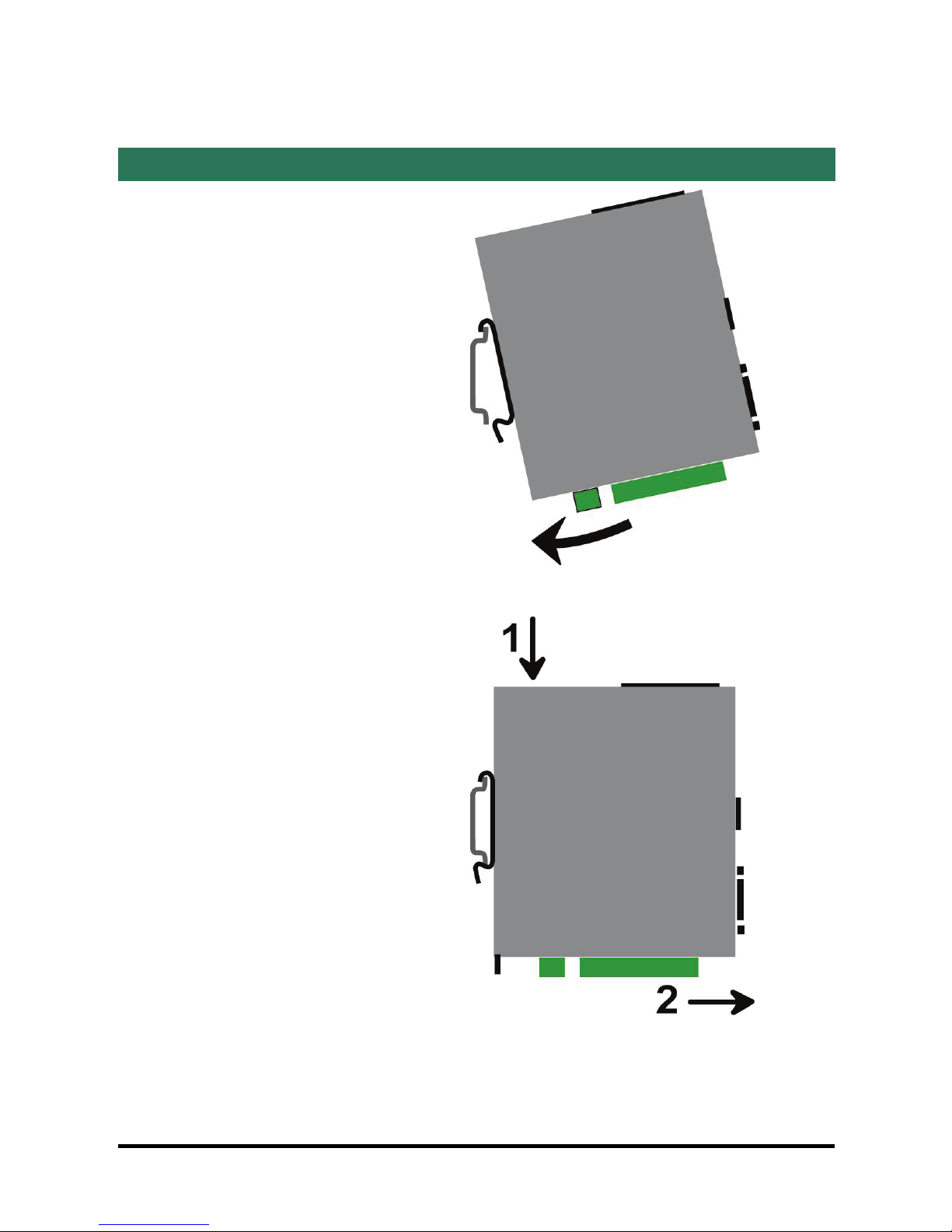
9 Mounting the product on a DIN rail or removing it
Mounting the unit on the DIN rail
This unit should be mounted on 35
mm DIN-rail, horizontally mounted.
Removing the unit from the DIN rail
IPL-3G UMTS router Page 15
PRODUCT DESCRIPTION
Page 16 IPL-3G UMTS router
10 Cooling
To avoid obstructing the airflow around the unit, the spacing must be at least 25
mm above and below, and 10 mm left and right.
11 RS232 interface
The RS232 data rate can be tuned from 1200 to 115200 b/s with parity (even / odd) or no
parity.
The data terminal must be less than 10 meters far from the modem.
Cables can be provided to connect the product to DTE and DCE as follows :
RS232 cables (L=1m)
Code User connector Cable function
CAB592 SubD 9 male To connect a DCE to the IPL-3G
CAB593 SubD 9 female To connect a DTE to the IPL-3G
CAB609 Wires To connect a device providing a specific
connector
PRODUCT DESCRIPTION
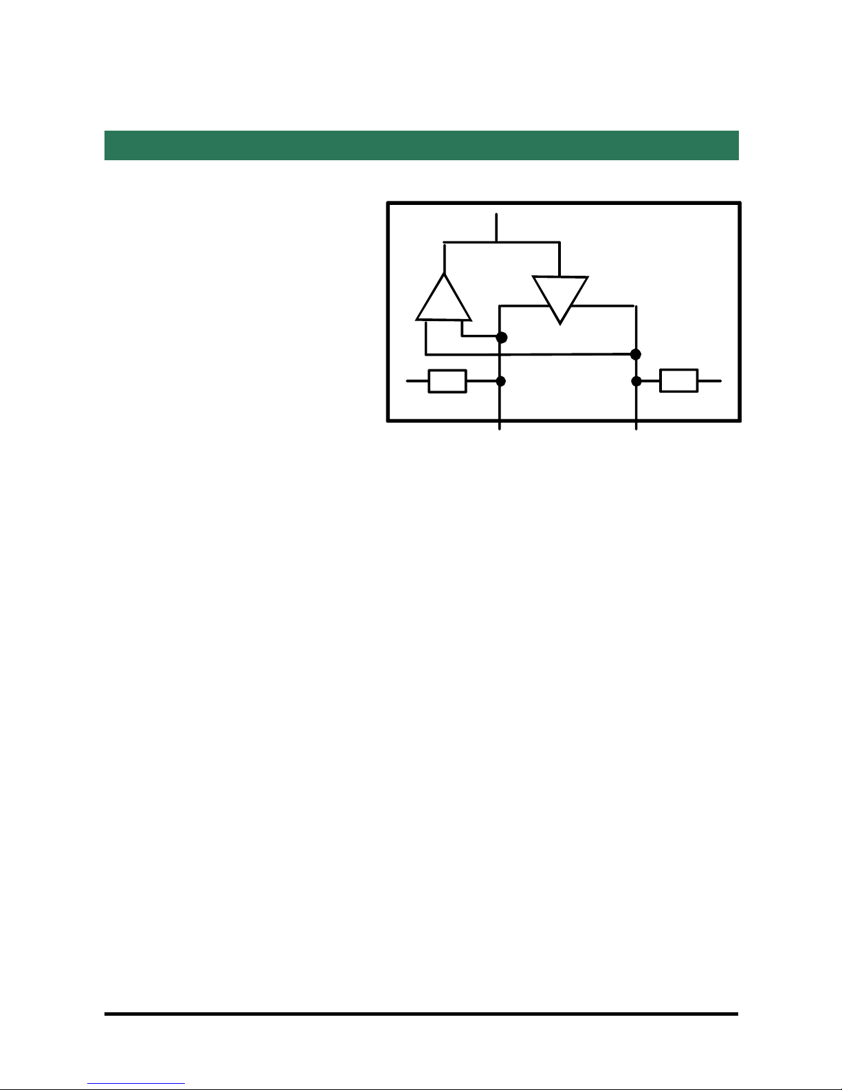
12 RS485 interface
The RS485 serial interface is
provided on the front panel 2
pins screw-block.
Polarisation resistors
1 Kohm bus polarisation
resistors are included inside
the product.
-
1K 1K
+SW1
B(+) A(-)RS485
RS485 line adaptation
For a several meters long connection over the RS485 local interface, it is not
necessary to adapt the RS485 line. For a longer distance, connect a 120 Ohm
resistor at each end of the line.
IPL-3G UMTS router Page 17
PRODUCT DESCRIPTION
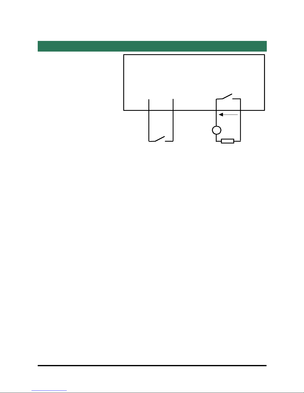
13 Digital input and output
Digital output :
Max. voltage : 48 VDC
Max. current : 500 mA
Digital input :
Maximum voltage : 20 VDC
F+ F-
78
Digital output
3V3 In
56
Digital input
Page 18 IPL-3G UMTS router
+V
IPL router
-
I max = 0,5 A V < 48 VDC
I < 0,5 A
GETTING STARTED
IPL-3G UMTS router Page 19
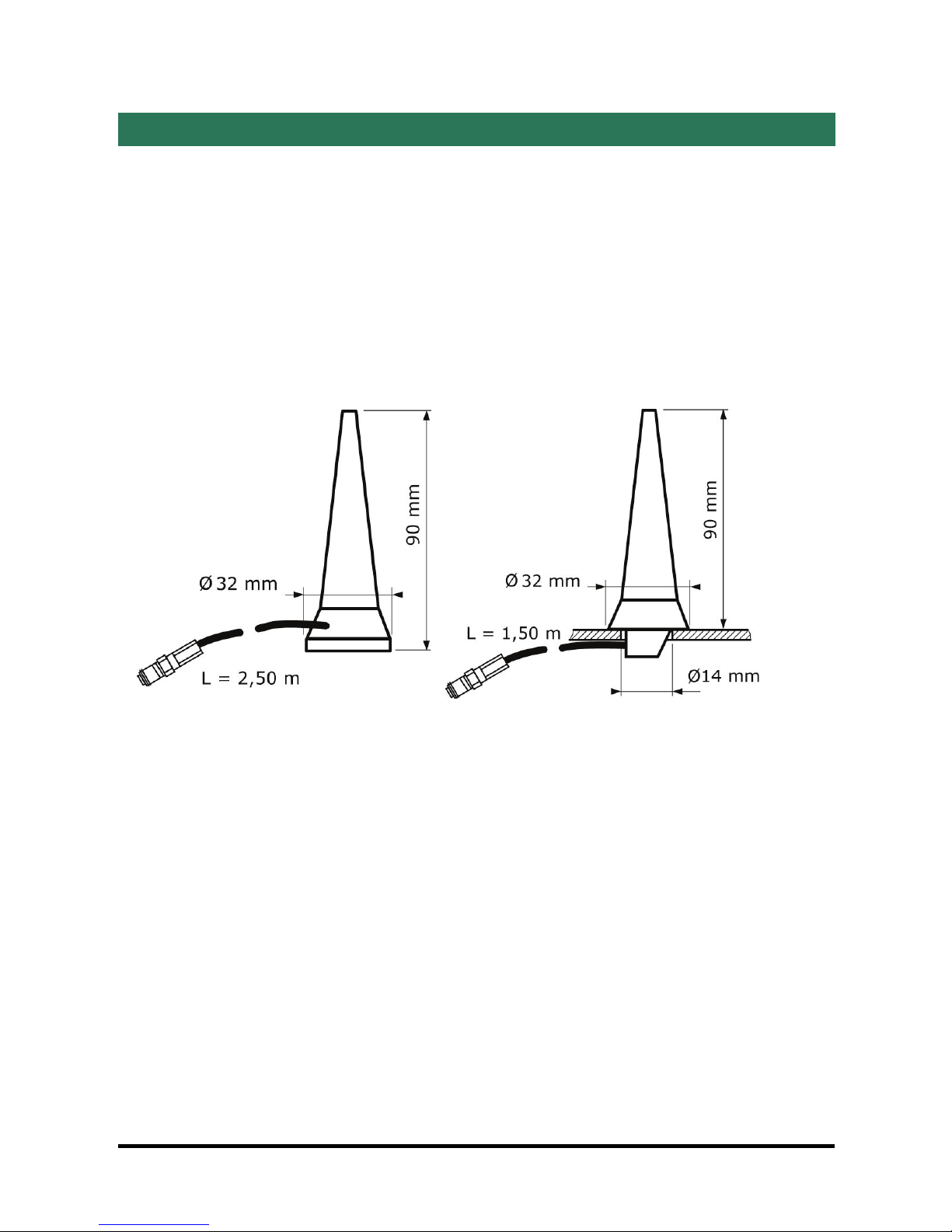
1 Connecting the antenna
If the cabinet in which the router has to be installed is made of metal, the antenna
has to be installed outside the cabinet; for instance on its top.
The antenna must be ordered separately; the models below are available :
• 90 ° antenna (ANT210 ).
• Magnet mount antenna (ANT211)
• Roof antenna (ANT212)
ANT211 ANT212 (1,50 m)
GETTING STARTED
Page 20 IPL-3G UMTS router
2 Installing the SIM card
Before installing the SIM card into the router, its PIN code be cleared.
The PIN code can be cleared using a usual telephone or a smart phone.
Step 1 : Install the SIM card
• Power off the router.
• Remove the anti-steal lid at the top of the product
• Press the SIM card eject button and remove the SIM card drawer.
• Insert the SIM card SIM card drawer.
• Slid the drawer back into the unit and make sure it locks into place.
Step 2 : Check the reception signal strength
• Switch-on the router
• The led first lights red and then green.
• The power indicator lights green.
• The reception led flashes to indicate cyclically the reception signal strength.
The reception indicator must flash at least 2 times to ensure a reliable connection.
If the reception led flashes only one time, it means that the reception signal is poor;
the reception conditions have to be improved.
If the reception led remains off or remains off, it means that the 3G service cannot be
received at that location or that the antenna is not connected or damaged.
• If the led lights red, it signifies that the PIN code of the SIM card
has not been cleared.
This manual suits for next models
15
Table of contents
Other ETIC Network Router manuals


