airria MU1000-0-075 User manual

1
v1.3
USER’S MANUAL
Decentralized ventilation system AIRRIA-
MU1000-0-075
WWW.AIRRIA.BE

2
v1.3

3
v1.3
1. Object
This user’s manual describes the functioning and explains how to use Airria’s ventilation system:
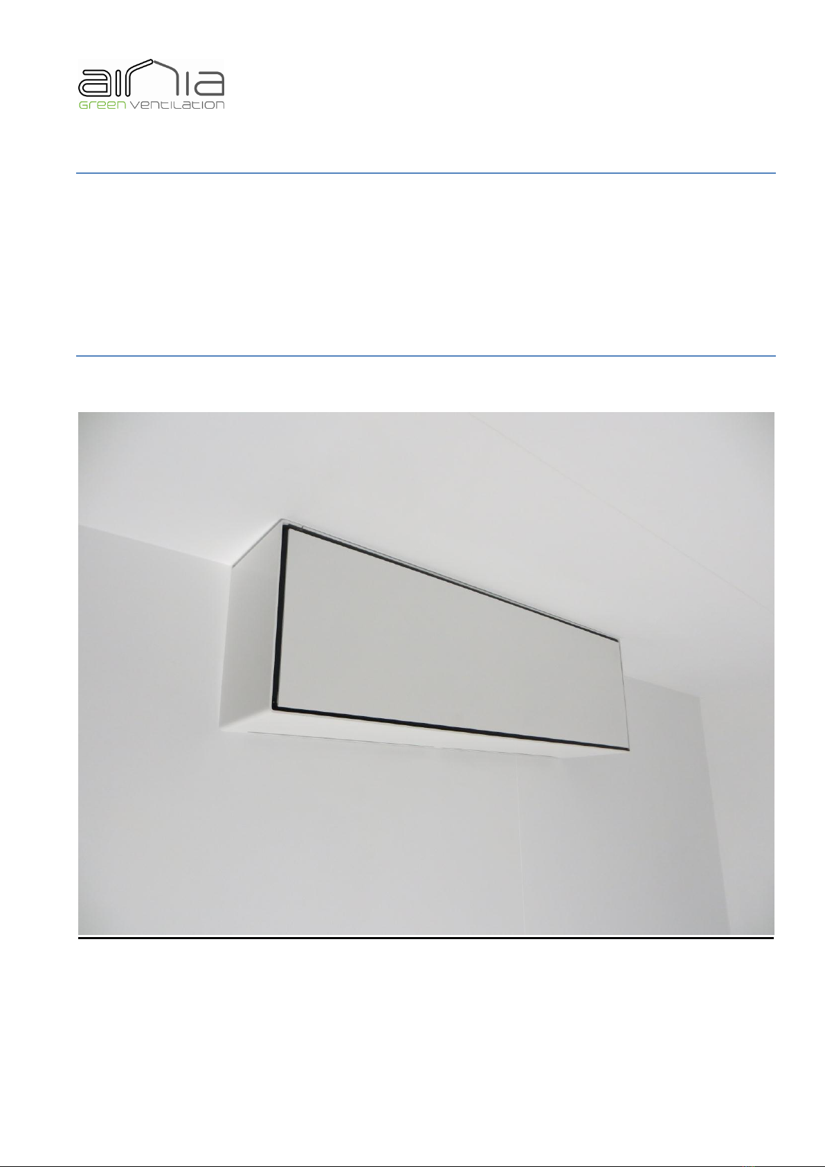
-Airria mural ventilation
With Airria-MU1000-0-075 decentralized ventilation system, including a heat recuperation system,
you have acquired a high-end product. This product improves your home and your well-being, and
protects you from the damages caused by humidity and mold inside your house.
Ventilating your house by opening the window, particularly during the cold season, now belongs to
the past. Starting from now, renewing the inside air (vitiated air) by outside air (fresh air), is automated.
The fresh air supply is constantly preheated in the heat exchanger, where the vitiated air’s heat is
transferred to the fresh air. This heat transfer improves your home, lowers your heating costs, and the
CO2emission into the atmosphere.
Typically, a 4-people family produces an average of 10 to 14 liters of condensation per day. This
condensation comes from cooking, laundry, personal hygiene, and the living beings’ respiration (plants,
animals, humans). This condensation production increases the absolute humidity of the inside air, and
furthers the appearance of mold that can be harmful to the building’s structure. By replacing the vitiated
air by fresh air, Airria-MU1000-0-075 ventilation extracts this humidity excess inside the building, as
well as the emanations from the floorings, furniture, and the CO2 excess, that can lead to exhaustion and
headaches.
1.1 Indications to the good use
Please read carefully this user’s manual and follow the instructions it contains. Please pay attention
to the warnings and precautions.
Never operate the Airria-MU1000-0-075 ventilation unit without filters. Use only Airria original
filters, to ensure the cleanliness of the system, its good functioning and it longevity.
The Airria-MU1000-0-075 ventilation unit can only be operated after its proper installation.
Never cover the Airria-MU1000-0-075 ventilation unit or one of its components with for example
curtains or blinds. A one-meter minimal distance has to be respected between the unit and any object
(wardrobe, chandelier, etc.), to ensure the good performances of the unit.
The Airria-MU1000-0-075 ventilation unit was designed to be operated continuously, and to thus
have a long lifetime. It is preferable that the unit is operated during the cold season, the fans and the
advanced electronics ensure, despite a continuous use, a weak energetic consumption of the unit. Only a
continuous use will ensure a permanent extraction of the humidity and the condensates present in the
Airria-MU1000-0-075 ventilation unit, and which could accumulate in the unit if it is not the case.
Please operate the Airria-MU1000-0-075 ventilation unit at maximum level (level 5) 15 minutes
every day to avoid any dust and/or condensates accumulation.
In order not to deteriorate the unit’s performances, especially during the cold season, it is preferable
to keep an interior temperature of at least 17°C.

4
v1.3
1.2 Maintenance and filters replacement
A signal light, based on a 4-months timer, will indicate you that it is time to check the state of the
filters.
For hygienic purposes, it is recommended to replace the filters at least once a year, ideally just
before spring. In order to ensure the good functioning of the Airria-MU1000-0-075 ventilation unit,
Airria-certified filters have to be used. If it is not the case, it could void the warranty, and Airria will not
be held responsible for any damages.
Note: Never interchange the two filters, at risk to redeploy, in the AHU, all the particles held
in the filters.
We hope you appreciate your new Airria-MU1000-0-075 ventilation unit.
2. Precautions and warnings
Please read the user’s and installation manuals before any operation upon the unit.
- Installation: it can only be done by informed installers.
- Use: this unit cannot be used by people (included children) presenting a physical, sensorial, or mental
disability, or lacking any experience or knowledge, unless they were informed and coached before.
- Finger-jamming hazard: during the opening of the hood, always ensure you are in a correct position.
Never open the hood while in a position where your arms and legs are tense.
- Electric hazard: before any manipulation, always start by turning off the switch of the main electric
board.
- Electric hazard: before any manipulation, always start by turning off the unit with the ON/OFF switch.
- Electric hazard: if the alimentation cable is damaged, it must be replaced by the manufacturer, its after-
sales service, or people with similar qualifications, in order to avoid any hazard.
- Finger-jamming hazard: during the change of filters, always start by turning off the unit with the
ON/OFF switch.
- Only use Airria filters (www.airria.be) to ensure correct functioning of the unit.

5
v1.3
3. Introduction
Airria-MU1000-0-075 ventilation units are conceived to ensure the basic hygienic ventilation, needed
for any residential building. The main advantages of decentralized Airria systems with heat recuperation
are:
- The end of ventilation networks that are hard to maintain, to make airtight, and to calibrate
- The pre-calibration of the flow rates
- The recuperation of the heat contained within the vitiated air, to pre-heat the fresh air, without any
electric resistance
- The filtration of the fresh and vitiated air.
4. Description
The decentralized, double-flux system is made of an active part (AHU : air handling unit) and a
casing.
The AHU contains a heat exchanger recuperator, which is a counter-flow exchanger with plates. The
2 flows circulation is made by 2 radial fans, low tension, with continuous current. The ventilation unit
also contains 2 filters, one for each flow, placed upstream the fan and the exchanger, for each of the
flows, so these key elements can be protected. The flow rates can go from 15 to 75 m³/h, for an
efficiency of 80 to 68% respectively. The audible level (Lw) at minimum flow is inferior to the superior
acoustic level of comfort, which if of 25 dBa. The maximum electric consumption is 45 Watts. The
electric connection is made with 230 Volts AC.
The AHUs are then integrated into casings that are manufactured independently. To avoid polluting
the AHU during works, it is inserted in the casing once it is definitively installed.
Two different casings exist: one for walls and one for windows.
The wall casing can be installed on any type of wall, and very easily. The installation only needs two
holes to let in and out fresh and vitiated air respectively. Its dimensions are fixed: 316 mm in height,
220 mm in depth and 1000 mm in length.
Electrical connection must be planned up to the casing, and go outside with an extra length of at leat
0,5 m (3G1,5).
Filters must be inspected at least twice a year and, if needed, replaced once a year.
A wireless remote “RF” allows:
-To select between 5 pre-calibrated flow rates
-To access the “boost” and “sleep” functions
-To change between simple-flow and double-flow modes.

6
v1.3
Depending upon the installations, a network can be realized:
-One remote can control several AHU (centralized command)
-Several remotes (maximum 10) can control the same AHU (co-existence of centralized and local
remotes).
5. AHU utilization
Make sure that the ventilation unit was correctly installed by an expert, according to the assembly
instructions, and that the unit is not damaged. The air input and output from the inside and outside
should not be covered or obstructed.
5.1 First use
5.1.1 Opening of the casing
For stability and security reasons, make sure to always have your shoulders at the same height as the
casing.
Place, on each side, the palms of your hands on the front face of the casing. Push to the buttress, and
relax. Then place all your fingers, except the thumbs, behind the face and pull it towards you.
Figure 1: First manipulation and removal of the hood
5.1.2 Turning on the AHU
Turn the AHU on by positioning the ON/OFF switch, up and left of the AHU, on “ON”. The “ON”
button is activated when the line on the switch is pushed in.

7
v1.3
Figure 2: Turning on the AHU
5.2 Common use
By default, the AHU runs at level 1 (minimum level)
Figure 3: Control panel
To increase the ventilation level: Press R5. Each pressing will lead to an emission of one of more
beep(s) corresponding to the ventilation level
Level
Flow [m³/h]
1
15
2
25
3
36
4
50
5
75

8
v1.3
To decrease the ventilation level: Press R6. Each pressing will lead to an emission of one or more
beep(s) corresponding to the ventilation level.
To go into simple flow/double flow mode: Press R4 to go from simple flow mode to double flow
mode, or the contrary. Each pressing of the R4 switch will make the LED twinkle either in purple
(simple flow), or in blue (double flow).
Simple flow mode:
When the DEV switch is on position 1, the AHU will operate in extraction mode only.
When the DEV switch is on position 2, the AHU will operate in pulsion mode only.
Double flow mode:
The DEV switch is nonfunctional.
Boost mode:
Keep R5 switch pushed until you hear a succession of beeps (around 4 seconds), then let go. The
UHA will operate at maximal level (level 5) during 15 minutes, then will operate again at level 1
(minimal level) automatically.
Sleep mode:
Keep R6 switch pushed until you hear a succession of beeps (around 4 seconds), then let go. The
UHA will shut down during 2 hours, then will operate again at level 1 (minimal level) automatically.
Humidity mode:
When the AHU is equipped with a humidity sensor, it can be operated in manual mode (level 1 and
5) or in automatic mode (level 2, 3 and 4).
In manual mode, the AHU operates at its minimum level at level 1 and its maximum level at level 5,
regardless of the relative humidity of the room.
In automatic mode, the AHU continuously regulates the speed of its fans depending on the set point.
AHU therefore ensures that the humidity in the room is at most equal to the requested value.
Level
Outflow [m³/h]
RH [%]
1
15
undefined
2
undefined
80
3
undefined
70
4
undefined
60
5
75
undefined

9
v1.3
Notes:
In some special cases, the moisture may remain too high in the room, even if the flow is at its
maximum. This will be seen in those situations:
- The momentary abnormal weather conditions make that the indoor relative humidity may not be
lower than the set point (very hot and humid weather).
- A continuous generation of moisture is generated in the room and the ventilation system is
undersized (number of units is not sufficient).
In these two cases, it is possible to manually select level 1 (minimum flow).
CO2 mode:
When the AHU is equipped with a CO2 sensor, it can be operated in manual mode (level 1 and 5) or
in automatic mode (level 2, 3 and 4).
In manual mode, the AHU operates at its minimum level at level 1 and its maximum level at level 5,
regardless of the rate of CO2 in the room.
In automatic mode, the AHU continuously regulates the speed of his fans depending on the set point.
AHU therefore ensures that the CO2 in the room is at most equal to the requested value.
level
outflow
[m³/h]
CO2 rate
1
15
Undefined
2
Undefined
1700
3
Undefined
1400
4
Undefined
1100
5
75
Undefined
Notes:
In some special cases, the indoor air quality may remain too poor in the room, even if the flow is at
its maximum. This will be seen in those situations:
- Conditions of exceptionally poor air quality and probably temporary make that the indoor air
quality cannot be below the set point (air intake very close to a combustion engine,....).
- A continuous generation of pollution is generated in the room and the ventilation system is
undersized (number of units is not sufficient).
In these two cases, it is possible to manually select Level 1 (minimum flow).
5.3 Remarks

10
v1.3
In order to ensure a healthy room and a continuously renewed interior air, it is recommended to
operate the AHU permanently at level 1 or 2. Operate at a superior level for a limited time if necessary.
During the winter, it is recommended to operate the AHU every day at its maximal level (level 5)
for 15 minutes, using the “boost” mode, in order to avoid the accumulation of condensates inside the
AHU.
It is recommended to let the AHU in the bedrooms operate a minimal level during the night. Use the
“sleep” mode is the AHU represents any discomfort to falling asleep.
The R1 switch is only for the installators. It allows them to define the parameters of the Airria-
MU1000-0-075 ventilation unit.
6. Use of the remote
Figure 4: Télécommande
6.1 Using a standard, 3-buttons remote, without on-demand ventilation
1. A first push on the remote uses the last function emitted by the remote. A second
push will change the sent command.
2. The up arrow (P3) increases the ventilation flow. The down arrow (P2) decreases the
ventilation flow.
3. The P1 button allows to switch from double flow to simple flow modes, and back.
-Double flow ventilation mode is indicated by the LEDs 1, 6 and 7
lightning up.
-Simple flow ventilation mode is indicated by the LEDs 1 and 7 lightning
up.
4. A long push (2 seconds) on the down arrow (P2) will put the system in sleep mode,
which stops the ventilation for 2 hours. After this sleep period, the AHU operates
again at level 1 (minimal level).

11
v1.3
5. A long push (2 seconds) on the up arrow (P3) will put the system in boost mode,
which puts the ventilation at maximum level for 15 minutes. After this boost period,
the AHU operates again at level 1 (minimal level).
6.2 Changing the battery of the remote
1. Using a small flat screwdriver, open the battery casing, below the remote.
2. Replace the battery, positive pole towards the exterior (front face). (CR2430, 3V
battery).
3. Close the casing.
7. Linking a AHU and a remote
7.1 Linking a AHU with a standard, 3-buttons remote
1. Push the R2 button and keep it pushed down. The buzzer emits a short beep, followed by a
continuous beep.
2. While keeping the R2 button pressed down, press once a button of the remote. The remote
emits a signal, indicated by LEDs 1 to 6 lightning up one after another.
3. Link of the remote to the AHU is signaled by the beep of the AHU now being intermittent.
You can now let go of the R2 button.
7.2 Linking a AHU with a “presence captor, 1-button” remote
1. Push the R2 button (black) twice, and keep it pushed down on the second time. The buzzer
emits a short beep at each pressing, and then a continuous beep.
2. While keeping the R2 button pressed down, press once a button of the remote. The remote
emits a signal, indicated by LEDs 1 to 6 lightning up one after another.

12
v1.3
3. Link of the remote to the AHU is signaled by the beep of the AHU now being intermittent.
You can now let go of the R2 button.
7.3 Removing a remote
1. Push the R3 button and keep it pushed down. The buzzer emits a short beep, followed by a
intermittent beep.
2. Press once a button of the remote. The remote emits a signal, indicated by LEDs 1 to 6
lightning up one after another.
3. Removal of the link between the remote and the AHU is signaled by the beep of the AHU
now being continuous. You can now let go of the R3 button.
7.4 Removing all remotes
1. Push the R3 button twice and keep it pushed down the second time. The buzzer emits a short
beep, at each pressing, and then an intermittent beep.
2. Press once a button of the remote. The remote emits a signal, indicated by LEDs 1 to 6
lightning up one after another.
3. Removal of the link between the remote and the AHU is signaled by the beep of the AHU
now being continuous. You can now let go of the R3 button.
8. Shutdown and reboot of the AHU
During a power shortage or the AHU being turned off via the ON/OFF switch, the fans stop
progressively. When the power is back or the AHU is turned on via the ON/OFF switch, the AHU
operates in the last mode that was used before the shortage or the stop.
9. Changing the filters
Remark: Never interchange the two filters: this could cause redeployment, inside the AHU, of
all the particles held in the filters.
The clogging of the filters cannot be avoided, and they must be regularly replaced. The replacement
frequency of the filters is based on a timer integrated into the AHU. The timer counts the operating
hours of the unit, and the red LED of the unit stay continuously lit up once the timer delay is over (4
months). Once the timer is over and the red LED lit up, please take the filters out of the unit, check them
and if necessary, clean or replace them.
9.1 Choosing a filter

13
v1.3
Several types of filters can be placed inside the Airria-MU1000-0-075 ventilation unit. By default,
the AHU is equipped with a G4 filter on the fresh air side, and a G4 filter on the vitiated air side. For a
standard use, the G4 filter is enough.
To retain micro-particles, use a M5 filter (fresh air side only)
For people suffering from allergies, use a F7 filter (fresh air side only)
Filter type
Description
Reference
G4
Standard
FI01-G4
M5
Microparticules
FI01-M5
F7
Allergies
FI01-F7
Use only Airria-manufactured original filters. Otherwise, Airria cannot guarantee the air quality,
and will not be held responsible for any malfunction of the AHU.
9.2 Changing the filters
No tool is needed to change the filters, but you have to wear gloves. Both filters always have to be
replaced at the same time.
9.2.1 Open the hood
See section 5.1.1
9.2.2 Turn off the unit
Turn the Airria-MU1000-0-075 ventilation unit off by pushing the ON/OFF switch (up and left of
the AHU) into the OFF position (Figure 5). The unit is off when the little circle of the switch is pushed
down.

14
v1.3
Figure 5 : Turning OFF the UHA
9.2.3 Wait for 30 seconds
Wait for 30 seconds to be sure that the fans are completely stopped.
9.2.4 Take the filters
Take both filters out of the unit, as pictured on Figure 6, by pulling the little handle that is provided.
Figure 6: Taking the filters
Clean the frame if needed.
9.2.5 Take the plastic protection
Take the plastic protection off the new filters as shown in Figure 7.
Figure 7: Taking off the plastic protection
9.2.6 Insert the new filters
Insert the blue drawer on the fresh air side, on the left, as indicated on Figure 8.

15
v1.3
Figure 8: Placing the blue filter on the fresh air side (left) of the AHU.
Insert the black drawer on the vitiated air side. Push lightly downside, as shown on Figure 9.
Figure 9: Placing the black filter on the vitiated air side (right) of the AHU.
If the red LED is still lit up, press button R4.
9.2.7 Turning the unit on again.
Turn the Airria-MU1000-0-075 ventilation unit back on, by pushing the ON/OFF switch, up and left
of the AHU, into the ON position (Figure 10). The unit is on when the little line of the switch is pushed
down.

16
v1.3
Figure 10: ON/OFF switch of the AHU in « ON » position
9.2.8 Closing the hood
Place the palms of your hands on the front side of the casing, and push it as far as you can.
Figure 11: Closing the hood
10. Maintenance
The Airria-MU1000-0-075 ventilation unit only requires a little bit of attention.
10.1 Cleaning the external grid
It is recommended to clean the external grill, at least once a year, preferably during autumn.
10.2 Cleaning the interior part of the AHU
Clean regularly the casing of the AHU, with a slightly damp cloth.
Warning! Never use acidic or corrosive products to clean the AHU! Never use a steam cleaner!

17
v1.3
11. Performances and technical characteristics
- Each receptor can memorize up to 10 emettors
- RF remote battery: CR2430 3V
12. Warranty
Recording device (for validity)
e_mail:
Phone number:
address:
number of devices:
Table of contents
Other airria Fan manuals