Genvex ECO 300 User manual

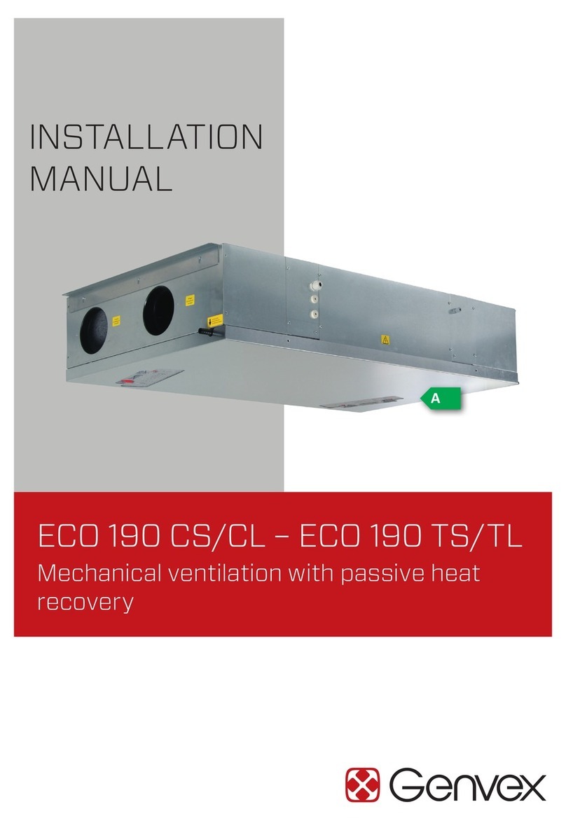
INSTALLATION
INSTRUCTIONS
ECO 300/ECO 300 XL
Mechanical ventilation with passive heat
recovery
A
THE AIR WE BREATHE

2
TABLE OF CONTENTS
Safety information..................................................................................................................................................................3
Functional description...........................................................................................................................................................3
Installation ................................................................................................................................................................................4
Dimensional sketch ................................................................................................................................................................ 5
Duct connection........................................................................................................................................................... 7
Duct system ...................................................................................................................................................................7
Condensation drain......................................................................................................................................................8
Insulation of ducts in cold attics ............................................................................................................................9
Insulation of ducts in warm rooms......................................................................................................................10
Post-heating of the supply air..............................................................................................................................10
Preheating of outdoor air.......................................................................................................................................10
Electrical installation...............................................................................................................................................11
Control and calibration of the system...............................................................................................................11
Optimal initial calibration of the system..........................................................................................................12
System maintenance................................................................................................................................................12
Access to internal parts..........................................................................................................................................14
Recommended maintenance intervals..............................................................................................................15
Spare parts..............................................................................................................................................................................16
Troubleshooting ....................................................................................................................................................................17
System not running....................................................................................................................................................17
No supply air.................................................................................................................................................................17
No exhaust air..............................................................................................................................................................17
Cold supply air.............................................................................................................................................................17
Alerts ..............................................................................................................................................................................17
Electrical diagram – Optima 270 ....................................................................................................................................18
Declaration of conformity.................................................................................................................................................19

FUNCTIONAL DESCRIPTION
ECO 300/ECO 300 XL is a horizontally mounted ventilation
system for ventilation in homes.
The system is equipped with a highly efficient counter-flow
heat exchanger, which recovers the heat in the exhaust air
from the home and preheats the fresh supply air.
ECO 300/ECO 300 XL can be configured as either right- or
left-facing depending on the installation conditions.
An integrated preheater can be selected for the system to
ensure that balanced air volumes can be maintained – even
with very cold outdoor temperatures.
You can also choose an integrated water level switch, which
ensures that the system stops and an alarm is shown on the
display if problems with the condensate drain occur (e.g.,
clogged floor drain).
ECO 300/ECO 300 XL has been designed for installation
outside the thermal envelope and has low heat loss due to a
very high thermal insulation performance. The system is not
intended for installation outside of buildings.
3
This manual also describes installation and service work to
be performed by a professional.
This device can be used by children aged 8 and over and by
people with reduced physical, sensory and mental capabili-
ties or lack of experience and knowledge, as long as they
are supervised or have been instructed in the safe use of
the unit and understand the dangers involved. Children
must not play with the device. Children must not clean or
maintain the appliance without supervision.
Subject to design changes.
Labelling
The CE mark represents Genvex’s assurance that the
product complies with all regulations laid down for the
product in accordance with relevant EU directives. The CE
mark is mandatory for most products sold in the EU,
irrespective of where they are made.
SAFETY INFORMATION

IMPORTANT:
Follow these instructions when installing the ECO 300/ECO
300 XL:
1) The system must be installed to allow the condensation
water to drain freely.
2) An airtight drain trap must be installed in a frost-free
location to compensate for fan pressure.
3) The drain trap must be a minimum of 50 mm in height.
4) Ensure the fall in the drain extends all the way to the
drain outlet.
5) Pour 1 litre of water into the condensate tray of the unit
to check that it drains correctly. Make sure the drain
trap is filled with water every year before beginning to
use the unit.
6) If the drain trap is installed in an area where
temperatures can drop below 0°C, then the drain trap
must be protected against freezing by a thermostat
and an electric heating element that turns on when the
temperature drops below +2C°.
7) The airflow volume for the supply air and exhaust air
must be adjusted before using the unit. It is important
to maintain an air balance inside the house.
8) We recommend closing the ceiling vents, etc., until the
system has been started up and adjusted.
KVM-Genvex A/S always recommends careful planning of
the installation space for your Genvex product in relation to
the location of living spaces. As this is a technical product
that contains fans and/or a heat pump, in rare cases, and in
combination with inappropriate installation conditions, it
may cause unsatisfactory noise or vibration nuisances. As a
rule, we always recommend installing the technical system
so that it is not located in the immediate vicinity of a
bedroom. Furthermore, when securing the Genvex system
to the building structure, it is recommended attaching it to
a heavy structural component such as concrete. It should
also be ensured that no sound or vibrations can be trans-
mitted through materials in contact with the technical
system. If there is a risk of propagation of noise and
vibrations, further installation of vibration-damping
material and sound-damping of installation rooms are
recommended.
For internal drainage
Draintrap 50 mm
Outdoor air
Exhaust
Extract air
Supply air
4
INSTALLATION

Dimensional sketch in mm.
1. Outdoor air
2. Exhaust air
3. Extract air
4. Supply air
5. Heat exchanger
6. Supply air fan
7. Exhaust fan
8. Filter outdoor air
9. Filter exhaust air
10. Condensate drain
11. Electrical connection
12. Bypass
The ECO 300/ECO 300 XL is supplied as either right- or
left-facing, as shown in the schematics below. If you want
the
condensate drain at the opposite end, simply remove the
front cover and back panel on the unit, then install the back
panel on the front and rotate the unit 180°.
Please note that the internal cable routing is at the front of
the system on the ordered model. Therefore, ensure an
appropriate distance at the rear cover if the system is
rotated relative to the model delivered.
The unit must be placed on a surface so that vibrations
from the unit are not transmitted down through the ceiling
and walls. The unit can produce up to 8 litres of conden-
sation per day during the winter, so the condensate drain
and the requisite drain trap must flow to the internal drain
without risk of frost.
To service and maintain the unit, there must be at least 600
mm of clearance in front of the unit and a surface that can
be walked on. If the unit is placed in the attic, then there
must be free access from the attic hatch to the unit.
Weight: 33 kg
15
Ø
584
260
598
292998
1058
181
491
160Ø
200Ø
1
2
3
4
5
6
7
9
8
11
10
12
Condensate drain
Right-facing
5

15
Ø
584
260
598
292998
1058
181
160Ø
200Ø
3
4
1
2
5
67
98
11
10
491
12
Condensate drain
Left-facing
6

3 m
1 m
3 m
Duct connection
A label on the front cover indicates which ventilation ducts
must be connected to the various connecting pipes.
Please note that the designations on the label are not valid
if the system is reconfigured from e.g. right to left after
delivery.
Connect supply air
Duct system from unit to supply air in living room.
Connect extract air
Duct system from wet rooms to the unit.
Outdoor air connected
Duct system from outdoor air intake hood/outdoor air
intake grille from outdoors or from the ground exchanger
to unit.
Exhaust is connected
Duct system from unit to exhaust hood/exhaust grille to
open air.
Duct system
It is recommended that the duct system is constructed
using spiral-folded pipes and fittings with rubber ring seals
to achieve a tight and long-lasting duct system.
To achieve a satisfactorily low noise level from the unit,
sound locks must always be fitted to the supply and
exhaust air duct system between the unit and the first
supply and exhaust air fittings.
Air velocities in the ducts should be dimensioned at a
sufficiently low rate so that no noise is generated by the
supply and extract air fittings.
When placing outdoor air and exhaust air hoods/gratings,
care must be taken not to short-circuit the two airflows,
thus causing exhaust air to avoid being sucked back in.
It is recommended that gratings be placed on the north or
east side of the house for optimal comfort in homes/
apartments.
Minimum distance: 3 metres
7

Condensation water drain
Condensate drain
The ventilation unit produces up to 8 litres of condensed
water per day. It is therefore important to mount the
condensate drain correctly. An ordinary Ø15 mm hose can
be connected directly to the ventilation unit.
It is important to make a loop on the hose, so that a drain
trap with a minimum of 50 mm is formed.
Water column
There must be a drop of 1% from the drain trap and the
hose towards the drain. If the unit is installed in a cold
environment the condensate drain must be insulated to
prevent the condensation water in the pipe from freezing.
However, it is recommended that the drain trap is installed
in a heated area to ensure that the water inside it does not
freeze. If installation problems make it impossible to
protect the condensate drain against frost using insulation,
then a thermostatically controlled heating wire must be
installed around the condensate drain. During operation,
the unit experiences internal negative pressure. Therefore,
it is necessary to ensure a water column height of at least
50 mm in the drain trap under all conditions.
If the heater is installed in a cold attic, the condensation
water drainpipe must be insulated so that the condensation
water in the pipe does not freeze.
We also recommend installing the drain trap in a heated
room below to ensure that the water in the drain trap does
not freeze.
If it is not possible to protect the condensation water
drainpipe against freezing by insulating it, then a
thermostatically controlled heating element must be
installed around the condensation water drainpipe.
When hanging on a wooden wall, a vibration damper is
recommended to avoid vibration transmission.
As an alternative to the looped drain trap, a Genvex
universal drain trap with hose connection can be used,
product no. 063289 (see the photo below).
8
Genvex universal drain trap
Tighten the supplied hose nozzle carefully until the O-ring
seals against the insert in the threaded connection, and the
condensation drain hose can then be connected to the
connecting pipe on the hose.
Check that the connecting pipe on the hose has been
installed correctly by pouring water into the condensate
tray and placing a finger over the outlet from the
connecting pipe. Check that no water escapes at
the O-ring seal.

Isolering af kanaler, alt. A
Isolering af kanaler, alt. B
Forkert isolering af kanaler
Insulation of ducts in cold attics
To utilise the full heat recovery capacity of the units, the
ducts must be properly insulated.
Genvex recommends the following:
Supply air and extract air ducts
To minimise heat loss from the duct system in cold attics,
supply and extract air ducts should be insulated with a
minimum of 100 mm insulation. If insulation form alterna-
tive (A) is used, it is recommended that the insulation is
made of 2 x 50 mm lamella mats with paper or aluminum
foil on the outside, and with staggered joints between the 2
insulation layers. If the ducts are laid out on the truss
frame, alternative B can be used. Insulation must always be
tightly wrapped around the ducts.
Outdoor air and discharge air ducts in cold rooms
It is recommended that outdoor air and extract air ducts
are insulated with a minimum of 50 mm insulation finished
with aluminium foil. Insulate the outdoor air duct to prevent
hot air in the attic from heating the outside air during
summer.
Be careful to seal where the exhaust duct passes through
the roof or out through the gable to avoid condensation
damage.
Contact your local supplier for guidance on national
insulation guidelines.
9

Insulation of ducts in heated rooms
Genvex recommends the following:
Supply air and extract air ducts
In a warm attic, the supply air and extract air ducts must
have 50 mm of insulation finished with aluminium foil.
Supply air and extract air ducts routed through heated
rooms in the home do not need to be insulated unless
cooling, a bypass or a geothermal heat exchanger are used.
In this case, the supply air duct must be insulated. In this
case, the supply air duct must be insulated.
Outdoor air and discharge air ducts
In warm attics and heated rooms in the home, outdoor air
and exhaust ducts must be have a minimum of 50 mm of
insulation. Furthermore, the outside of the insulation must
be covered with plastic or aluminium foil to prevent con-
densation water in the insulation.
Contact your local supplier for guidance on national insula-
tion guidelines.
When using a geothermal heat exchanger, it is recommend-
ed to add 100 mm of insulation to the outdoor air duct.
Reheating supply air
The counter flow heat exchanger cannot fully recover all
heat from exhaust air to supply air, so during winter the
supply air will be approximately 1-4°C lower than the
ambient temperature in the property. If the system is
intended for use in heating, then a water or electric heating
surface can be installed to heat the supply air to room
temperature.
Water heating surface
To protect the water heating surface against frost cracking,
a water frost sensor must be installed on the system and
the water heating surface must be insulated. The water
frost sensor is installed on the back of the slats of the
water post-heating surface. The sensor for controlling the
motor valve is installed in the supply air duct approximately
500 mm after the water heating surface so that it is not
affected by radiant heat from the heater. The water con-
nection to the water heating surface must be carried out by
an authorised plumber.
Electric heating surface
The sensor for controlling the electric heating surface is
installed in the supply air duct approximately 500 mm after
the electric heating surface so that it is not affected by
radiant heat from the heating unit.
Extract air
Supply Air
With water heating surface
500
Extract air
Supply Air
With electric heating surface
500
10

Electrical installation
Connection to the mains must be carried out by an author-
ised electrician. See the accompanying wiring diagram.
ECO 300/ECO 300 XL is prepared for external connection
of a 230 volt device plug, internet and display, BMS connec-
tion and
Genvex accessories.
See electrical diagrams and operating instructions for the
Optima 270 for further information
Important!
For functional and safety reasons, the unit
must be connected to a grounded socket suited
to the plug.
Control and calibration of the system
To achieve optimal system operation, it must be
commisioned using air measuring equipment.
If the system needs to be used before it is adjusted, then
the following can be done before commissioning the system:
1. Check that the ECO 300/ECO 300 XL has been mounted
correctly and that all ducts are properly insulated.
2. Check that the front cover can be dismantled so that it is
possible to carry out service and maintenance on the unit.
3. Check that the filters are clean (they may become dirty
after installation).
4. Check that the condensate drain is correctly fitted with
a drain trap and is protected from frost. Pour 1 litre of
water into the condensation water tray and ensure that
it drains freely through the condensate drainpipe.
5. Set all supply air valves so that the valve plugged into
the unit opens 3 turns from the closed position, while
the outermost valve opens 8 turns from the closed
position. The intermediate ones are opened between
4-7 depending on how close they are to the unit.
Set all exhaust air valves so that the exhaust air valve in
the kitchen opens 8 turns, the exhaust air valve in the
bathroom/toilet opens 7 turns and the extraction valve in
the utility room opens 6 turns from the closed position.
6. If a heating element is fitted to the system, the supply
air temperature is set to 0-3°C below the room
temperature in the property.
The system can now be put into operation and may operate
until the system is calibrated using ventilation measuring
equipment.
Preheating outdoor air
Electric preheater
At outdoor temperatures below 0°C and if software deicing
cannot be used, we recommend installing an electric
preheater to prevent ice from accumulating in the counter
flow heat exchanger.
It may be beneficial to use a factory-fitted, integrated
electric preheating surface (add-on accessory).
11
Connections for internet, display, BMS and add-on
accessories for the ECO 300/ECO 300 XL.

Optimal initial calibration of the system
Genvex recommends that the ventilation unit should be
calibrated by an authorised Genvex dealer before it is put
into operation.
Before starting the initial calibration, check that the 6
points in the section “Control and calibration of the system”
have been performed. Then start the unit:
Set the initial basic ventilation value, which is speed
2. To reduce energy consumption as much as possible,
first adjust the main air volumes to the desired levels by
adjusting the speed of the fans via the control panel.
Then adjust the supply air and exhaust air valves with air
measuring equipment (during the initial calibration of the
valves, remember to lock them and turn the baffle plate
in the supply air valves so that the air blows in the right
direction).
Then check the main air volumes again and fine-tune them
using the fresh air and exhaust air valves (remember to lock
the position of the valves after initial calibration).
G4/Coarse=Standardlter(coarselterclassG4)
F7/ePM1 =Pollenlter(nelterclassF7)
System maintenance
REMEMBER TO SWITCH OFF THE POWER BEFORE
OPENING THE UNIT.
Filters
When the filter timer reaches the set value for a filter
change,
this will appear in the text of the Optima Touch display
or in the Genvex app or be indicated with a yellow flashing
light in Optima Basic. This means that the filters must be
replaced/cleaned.
The system is stopped by pulling the plug out of the socket
or via the switch on the electrical panel. The front doors are
opened and the filters removed. Once the filters have been
cleaned/replaced, the front doors are closed and the filter
alarm can now be reset via the display or app. The system
then returns to normal operation.
If you want to replace the filters with a different time
interval, this can be done via the user menu.
Do not vacuum or clean the filter using pressurised
air. This will damage the filter!
Filter replacement
1. Open the filter plug.
2. Carefully pull out the filter and replace it with a new
filter.
12

Condensate drain
During the filter change before autumn, the condensate
drain should be checked to ensure it is not clogged with dirt
and to ensure there is water in the drain trap.
Pour 1 litre of water into the condensation water tray and
ensure that it drains away freely. If the condensation water
drain does not function properly, then this may result in
water damage to your home.
Counter flow heat exchanger
Inspect the counter flow heat exchanger annually. If it is
dirty, remove the unit and wash it in lukewarm water with
soap and rinse it in the bathroom with a shower head.
Fans
Remember to turn off the power.
Annually check the fan wheels for dirt.
Remove the front cover of the unit. Clean the fans with a
brush or bottle cleaning brush. Note: please do not remove
the balancing weights on the fan wheels, as this will lead to
an imbalance in the unit with a higher noise level and cause
more wear on the fans.
Supply air and exhaust air valves
Clean the vents by wiping them with a dry cloth. Ensure the
vent does not rotate causing the airflow to change.
Service
If you are unable to maintain your system, you can sign a
service agreement with the Genvex service department. If
the system is faulty, please contact the Genvex service
department.
100 mm
Water trap
To internal drain
50
13

Access to internal parts
1. Remove the screws from the front plate to access
internal parts.
2. Disassemble the bracket with the sensor mounted in the
exchanger. The exchanger can then be pulled out.
3. If a level sensor is installed in the system, this must be
unscrewed before the fan housing can be removed.
4. Dismantle the fan housing by pulling on it.
5. Dismantle the bypass by releasing the plug on the side of
the cassette.
6. Separate the two plastic flaps. The bypass cassette can
then be pulled out.
14

7. Remove the six screws on the cover at the top of the
system to gain access to the printed circuit board.
15
Recommended maintenance intervals
Component Maintenance Interval
Filter Replaced at set intervals so the unit is fully
efficient.
3–6 months
Fans Fans must be cleaned with a soft brush to ensure
operational safety and efficiency.
12 months
Counter flow heat exchanger Clean with water 12 months
General gaskets Give the gaskets on the unit a general check to
ensure they are intact
12 months
Supply air and exhaust air valves Check for dirt inside the supply air and exhaust air
valves. Clean as needed. Check that the valves
have the desired setting in relation to air volumes.
12 months
Air intake Check for dirt and grime inside the air intake and
exhaust air vents and clean as needed
12 months
Ventilation ducts Check the cleanliness of ducts and clean as
needed.
10 years

SPARE PARTS
7
10
53
1
2
49
11
12
8
6
Pos. Item no. Description
1 069875 OPTIMA 270 PCB
2 069876 I/O PCB
3070056 EC
070055 EC
90 Watt fan
170 Watt fan (XL)
4 070130 Bypass motor
5 072014 Counter flow exchanger
6 073001 Filter – F7 / ePM1 55%
6073006 Filter – G4 / Coarse 65%
7 073034 Assembled front cover
8 073041 Bypass flap, large
9 073042 Bypass flap, small
10 073045 Bypass mounting bracket
11 073046 Assembled bypass cassette
12 073047 Assembled rear cover
16

TROUBLESHOOTING
System not running
• Fuse in electric panel has blown, no voltage in the
system.
• One of the fuses in the system’s control board has blown.
• Loose cable, no voltage to the unit.
• Incorrectly set weekly program.
• Filter timer has switched off the system.
No supply air
• Defective supply air fan.
• Clogged supply air filter.
• Outdoor air grille clogged with dirt and leaves during
autumn or snow and ice during winter.
• Fuse on control board has blown.
• Unit is defrosting (supply air fan runs at reduced speed)
• Incorrect setting of Optima controls
No exhaust air
• Defective exhaust fan.
• Clogged exhaust filter.
• Fuse on control board has blown.
Cold supply air
Fault
• Heat exchanger is clogged.
• The exhaust fan is defective.
• The exhaust air filter is clogged.
• Disconnect the electric preheating surface from the
overheating thermostat (only systems with an electric
preheating surface installed).
• Air in heating pipe, defective thermostat/motor valve,
incorrect setting of control panel.
If none of the above errors are relevant, contact:
• During the warranty period (0-2 years), the installer from
whom the unit was purchased.
• After the warranty period (2+ years), the installer from
whom the unit was purchased or call the Genvex Cus-
tomer Centre on +45 7353 2700.
Please have the information from nameplate ready.
Alerts
See Optima 270 operating instructions.
17

18
ELDIAGRAM – OPTIMA 270
L2
GND
24VDC
A
B
1234 12341234 1234123 123
1
1
1
2
2
2 3
3
3
4
4
X1
X2
X3
X5
LED1 LED2
1
1
1
2
2
2 3
3
3
4
4
L1
L6
L8
L10
L11
L16
GND
GND
GND
GND
24VDC
24VDC
GND
GND
GND
GND
24VDC
A
B
Signal
Signal
0-10V
Sensor
Sensor
T8
T9
L4L3 AL3 BL3 CL3 DL20L21L17L18
H7 H9
L17
L18
L3
L4 L1
L6
L8
L10
L11
L16 L2
L22
F1F3 H1
H3
H14
H17
H7
H9
X1
MODBUS
Master
MODBUS
Display
MODBUS
CTS
RUN
ERROR
LAN OK
RJ45
ES 2010 - Optima 270
USB-mini
L
L
L
L
L
L
L
N
N
N
N
N
N
GND
GND
GND
GND
GND
GND
GND
GND
Sensor
3,3V
GND
24VDC
24VDC
GND
GND
GND
GND GND
24VDC 24VDC
A A
B B
GND
GND
0-10V
0-10V
Tacho
Tacho
Signal
Signal
Signal
0-10V
Sensor
Sensor
Sensor
Sensor
Sensor
T8
T9
R1
R2
R3
R4
R5
CR2032
8A2,5A
5x20mm 5x20mm
Rh
M
X5
L22
X1
X2
X3
A
B
GND
+24VDC
A
B
GND
+24VDC
A
B
GND
Signal
GND
+24VDC
+24VDC
GND
Signal
1
1
2
2
3
3
4
4
24
23
22
21
21
22
23
24 JRS
23/02/2021
Version 1,2
A
B
C
D
Mains connection
1x230V 50Hz, L, N, PE
Max: 10A
Electric Pre- / Reheat / Operating
1x230V 50Hz
Max.load 1800W
Aux. relay H17
1x230V 50Hz
ONLY control current
Sensor T8 Frost
Sensor T7 Extract air
Sensor T4 Exhaust air
Sensor T3 Outdoor air
Sensor T1 Supply air
Sensor T9 Option
External stop
EC fan Extract air
Blue
Yellow
EC fan Supply air
Blue
Yellow EC fan Extract air
1x230V 50Hz
Brown
Brown
Blue
Blue
Yellow/green
Humidity sensor P1
EC fan Supply air
1x230V 50Hz
Belimo CM230
ON/OFF Bypass
2x230V 50Hz
White
Control signal for
Rotor,
Bypass,
Motorvalve
Modulating Reheating
Modulating Preheating
Potential free input
for optional:
Humidistat,
Extractor hood
White
White
Modbus Master /
ES1048
Brown
Blue
Yellow/green
Yellow/green
Yellow/green
Brown
Blue
Brown
Blue
Flow sensor Extract air
Flow sensor Supply air
Optima Touch Display /
Optima Basic Display
Optima Touch Display /
Optima Basic Display
Modbus Master /
ES1048
Modbus CTS
Brown
Blue
Green / Blue
White / Yellow
Brown / Red
I/O PCB
Please ensure sufficient
earthing of the installation
Service menu EC 10 = Right
LED 1
On = Internet connection
LED 2
1 flash = External stop
2 flashes = Sensor error
3 flashes = Humidity sensor error
4 flashes = Fan error
5 flashes = Sensor Frost error
6 flashes = Fire failure / test
7 flashes = Fire failure - Damper 1
8 flashes = Fire failure - Damper 2
9 flashes = Fire failure - Box 1
10 flashes = Fire failure - Damper 3
11 flashes = Fire failure - Damper 4
12 flashes = Fire failure - Box 2
13 flashes = Rotor alarm

19
DECLARATION OF CONFORMITY
The declaration of conformity can be found on our website: www.genvex.com

08:471-2302
KVM-Genvex A/S • Sverigesvej 6 • DK-6100 Haderslev • Tel.: +45 73 53 27 00 • [email protected] • www.genvex.com
THE AIR WE BREATHE
Genvex – the original Danish ventilation system
Genvex is a true Danish original. We started producing ventilation
systems in 1978 and are still the front runners when it comes to
development and production of the most innovative and durable
ventilation systems on the market.
Our units are installed in thousands of homes, providing clean, fresh air
free from pollen, dust and harmful particles. They help lots of families
with maintaining a healthy and comfortable indoor climate and prolong
the longevity of the house itself. With very high heat recovery rates, a
Genvex system lets you recover and reuse up to 95 % of the heat inside
your home. As a result, our units provide a strong contribution to energy
savings in both in family homes and in society as a whole.
All
Genvex
systems are
rated with
energy label
A
Genvex develops ventilation units
that use as little energy as possible,
whilst still being as efficient as
possible. This is good for the
environment – and will also save you
money. Our units comply with all
applicable standards and are easy
to use, install and maintain. Last –
but not least – all Genvex units have
compact dimensions that makes
them easy to install seamlessly in all
types of homes – large or small.
Genvex is a part of the Swedish
NIBE Group, which has specialised
in providing environment-friendly
energy solutions throughout the last
70 years. The NIBE group consists
of more than 140 companies all over
Europe.
Please visit www.genvex.com to see a list of our distributors
This manual suits for next models
1
Table of contents
Other Genvex Fan manuals

Genvex
Genvex GE ENERGY 3 User manual

Genvex
Genvex ECO 375 TS User manual

Genvex
Genvex OPTIMA 270 User manual

Genvex
Genvex ECO 275 User manual

Genvex
Genvex ECO 400 XL User manual

Genvex
Genvex ECO 190 CS/CL User manual

Genvex
Genvex ECO 360 R User manual

Genvex
Genvex ECO 190 XL User manual

Genvex
Genvex ECO 375 User manual
Popular Fan manuals by other brands

Sterr
Sterr IDM operating instructions

ELECTROTEK
ELECTROTEK ET-F16SF instruction manual

Broan
Broan ZB110ML installation guide

Minka-Aire
Minka-Aire CONCEPT I WET Instruction manual warranty certificate

Porcelanosa
Porcelanosa noken SEASONS 100239028 N199998966 instruction manual

Ebmpapst
Ebmpapst K3G250-RE07-05 operating instructions