AirScape HEPA TOWER User manual

Order#:
S/N:
(Required for Warranty)
HEPA TOWER
Installation and Operation Manual
Thank you for purchasing an
AirScape® HEPA TOWER
Your HEPA TOWER has been designed to quietly filter
the air in a room for many years to come
The AirScape HEPA TOWER:
Pre-filter: High quality MERV 11 pre-filter
This HEPA Filter is rated at 99 95% efficiency
[European H13-Certified, test certificate included]
which offers 99 95% arrestance at 0 3 micron
particle size HEPA standard uses 0 3 microns
as the "lowest point" This means that the
filtration efficiency increases for particle
diameters both less than and greater than
0 3 microns
ECM Motor (High Efficiency) to quietly produce
high volume airflow in ten speed steps
(with optional remote control) capable of many
room air changes per hour
Adjustable Louvered Air Exit, which allows you to
direct the filtered air in 4 directions to create the
optimum airflow pattern through the room The
importance of a high to low airflow pattern can
not be overstated Correct Air Flow will minimize
Low Flow Areas in the room
Appearance; Outer Panels may be made in any
of the currently available materials
Maple Veneer Panels (shown)
White Painted Aluminum (ACP)
Black Painted Aluminum (ACP)
HEPA TOWER Installation and Operation Manual, 0221
©AirScape, Inc., 2021. All Right Re erved. Page 1

Please take a few minutes to read over this manual and its accompanying documents
Before power-up of the unit, inspect it for any damage that may have been sustained during shipping
DO NOT USE DAMAGED EQUIPMENT If you suspect this unit was damaged during shipping, contact AirScape
technical support by phone at 1 866 448 4187, or email at experts@airscapefans com
THEORY OF OPERATION
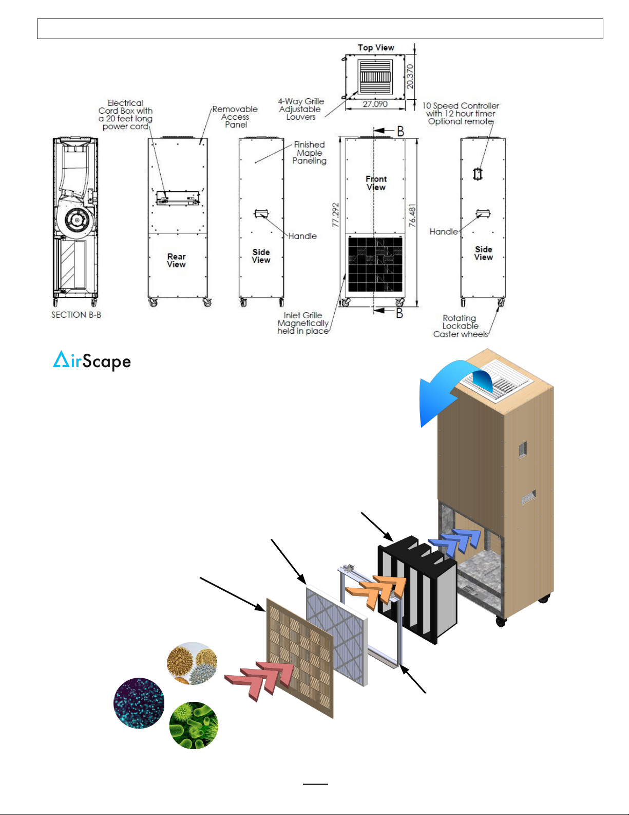
AirScape’s HEPA Tower was designed to greatly minimize exposure to airborne pathogens, pollen and
dust by quietly filtering the air in the room
The design intent was to create a mobile HEPA filter unit that would quietly filter any room, work space,
office space, conference room or waiting room to minimize the airborne transmission of viruses, viral
particles, and removal of pollen, fungal spores and dust, that can accumulate in indoor air
This stand alone unit recirculates and filters the air (HEPA=99 95%) in the space it is being used
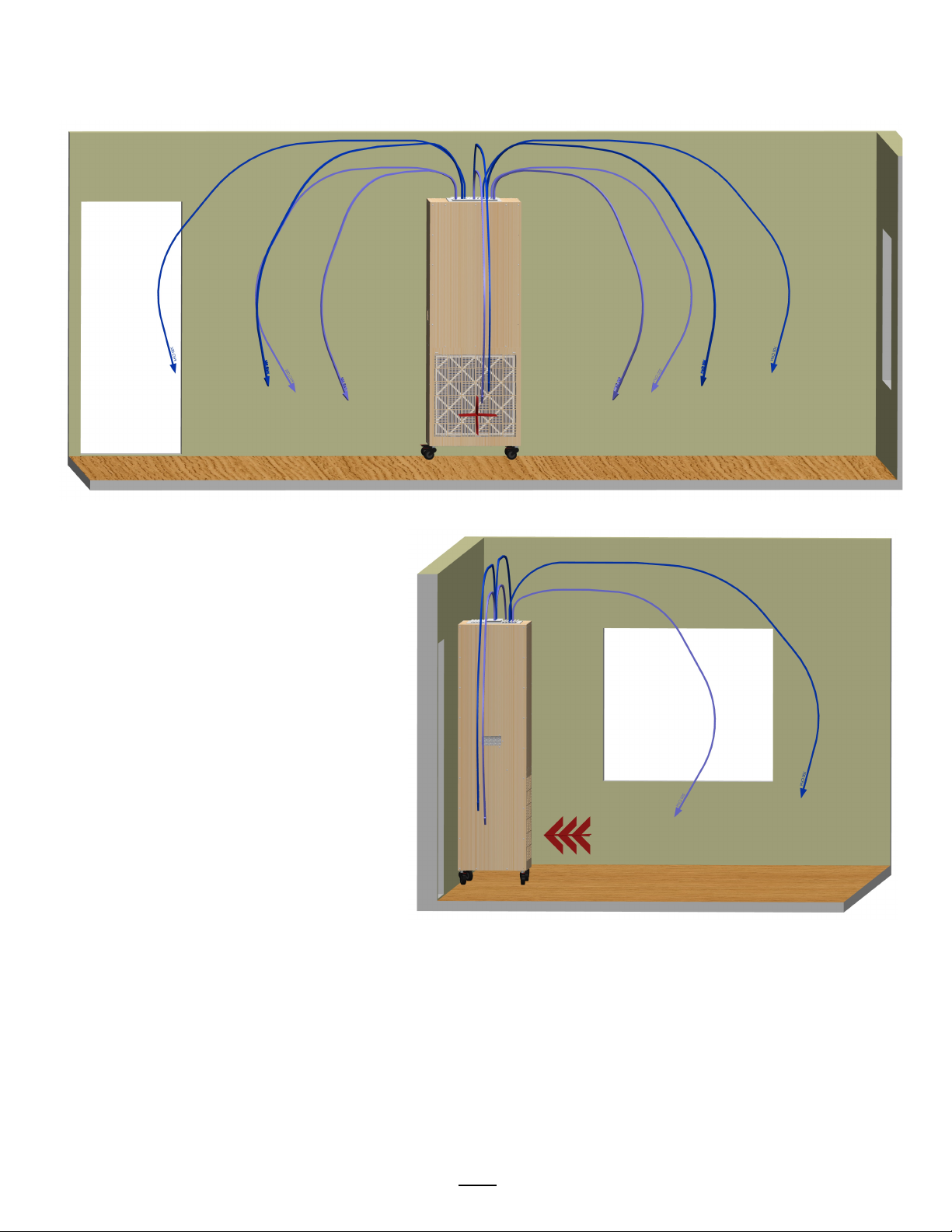
It works by pulling in contaminated air from low in the room and pushing the air up high thus creating an
airflow pattern [high to low] that reduces human exposure to contaminants
PURCHASE OPTIONS (not included)
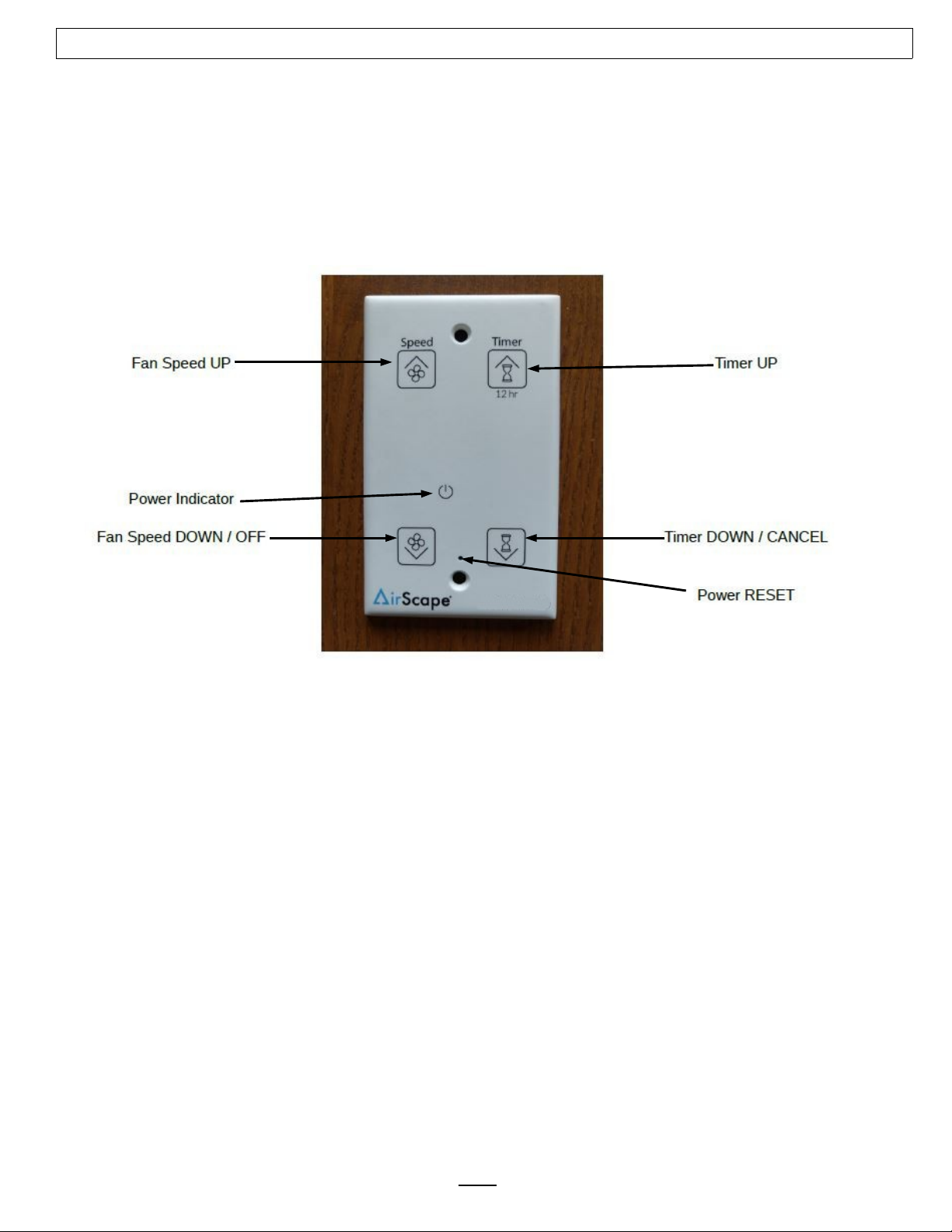
A wireless remote is an available accessory option for AirScape’s HEPA Tower The wireless remote is
NOT included as part of this fan’s standard control package The yellow manual included with these
accessories provides specific instructions for the installation and operation of the remote
If purchased
, the wireless remote receiver is connected to the fan electrical box at the blue RMT RJ45
port If purchased at the time of the purchase of the HEPA Tower, AirScape will install the remote
receiver in the unit If purchased after; Installation means removal of the rear panel, installation of the
remote receiver and blue Cat5E cable, an operational test and reinstalling the rear panel
Replacement HEPA Filter and MERV11 Pre-filters can also be purchased
SAFETY INFORMATION
•
The HEPA TOWER does NOT remove gasses
• The HEPA TOWER is not for use in professional kitchens
• Before servicing the Tower, unplug the fan from the wall receptacle
to reduce the risk of damaging
circuit boards, fire, electrical shock, or injury
•
A used HEPA Filter should be treated as “infected” or contaminated and discarded taking
precautions Avoid touching the filter material
• Perform periodic checks of the air flow pattern, physically feel air moving in and out of the HEPA
Tower and around the room
• When installing a new HEPA Filter avoid touching the filter material as this may damage (create a
hole in) the HEPA Filter and thus nullify the HEPA standard
• Strapping the unit to the wall using a few Rear Panel (access panel) screws is a good way to create
some earthquake protection (straps not included)
HEPA TOWER Installation and Operation Manual, 0221
©AirScape, Inc., 2021. All Right Re erved. Page 2

THE HEPA TOWER
HEPA Tower
HEPA TOWER Installation and Operation Manual, 0221
©AirScape, Inc., 2021. All Right Re erved. Page 3
HEPA FILTER
H13 (99 95%) Certified
1-2 year lifespan
MERV 11 Pre-Filter
2-3 month lifespan
Micro-Droplets
Viruses
Airborne Organisms
Fungal Spores
Pollen, Dust
Magnetic Inlet
Grille
Filter Frame
Screws in Filter Frame
to hold HEPA Filter,
Press-Fit Pre-Filter
Mobile
Clean air is supplied high in the room
Contaminated air returns to the Tower low
Creates a current of clean air to push contaminants
down and away
High efficiency ECM Motor
Large Air Flow of 940 CFM
Large HEPA Filter for long life

START-UP AND OPERATION
Before starting this Fan for the first time, verify that:
1 The HEPA Tower is standing on its wheels
2 The HEPA Tower’s power cord has been plugged into a ground tested, 120-volt outlet with
uninterrupted power
3 The area in front of the towers inlet (grille) is as unobstructed as possible
4 The Air Exit Louvers have been adjusted for proper Air Direction (see operational tips)
When running the HEPA Tower for the first time, make sure to observe it turning on, running at all of its
speed settings, and turning off, also verify Timer works at 1 Hour Setting
As shown above, there are four “buttons” on your fan’s control interface:
When the Digital Touch Controller (DTC) is connected to power, a red LED will illuminate
See the Power Indicator shown above
The AirScape Unit has ten speed settings Turn on the fan by touching FAN UP or TIMER UP The fan will
start at minimum speed Green LED’s will illuminate to indicate the speed setting
If the Fan was turned on by TIMER UP, the timer will be set to one hour and blue LED’s will illuminate to
indicate the timer setting Press or hold FAN UP to increase the fan’s speed to maximum Press or hold
TIMER UP to increase the length of time the Fan stays on in one hour increments until the desired time,
or the maximum time of 12 hours, is achieved
If the fan is already operating at minimum speed, touch FAN DOWN/OFF to turn off the fan; any time
remaining on the timer will be canceled If the fan is at maximum speed, press or hold FAN DOWN/OFF
to decrease the speed to minimum and once again to turn the fan off
Press or hold TIMER DOWN/CANCEL to reduce the time on the timer by one hour increments until the
desired time is achieved or the timer is canceled When the timer expires, the fan will turn off
automatically If the timer is canceled, the fan will remain on at its current speed
* Note: If untouched after a moment the selection LED’s will dim
** Note: If the Fan is on without a timer, the fan will run indefinitely
HEPA TOWER Installation and Operation Manual, 0221
©AirScape, Inc., 2021. All Right Re erved. Page 4

OPERATING TIPS
Make sure the Pre-Filter and inlet Grille are installed correctly Change the Pre-Filter every 2-3
months, change the HEPA Filter every 1-2 years
Use your HEPA Tower’s fan higher speed settings to clean your room quickly, then switch to its lower
settings to run it quietly and efficiently through the day
The Front of the Tower MUST remain unobstructed, with no objects closer than 24” to the face of the
Inlet Grille
Airflow through the room is very important and some time should be taken to visualize airflow
patterns to find the best spot for the Tower Note: Since the Inlet Grille of the Tower is low to the
ground it is wise to place the tower with it’s back against a wall leaving the Inlet Grille open to the
entire room and minimizing the airflow dead zone behind the unit
You can control where your tower’s airflow is directed by adjusting the louvers on the Air Exit
Grille (on top of the Tower) and increasing the speed of the fan Visualize the path air will travel from
the Air Exit Grille to the far corners of the room, downward over the floor and back into the Tower Inlet
Grille (see Airflow in a room below)
Objects in the room will “interfere” with (or redirect) the airflow An open door or window can change
the airflow pattern
AIRFLOW IN A ROOM
This room simulation shows the HEPA Tower (back against the wall) placement and shows a possible
airflow pattern These images can be used to visualize air flow through a space
Light blue airflow at 500 CFM
Dark blue airflow at 700 CFM
Red Arrows indicates mixed unfiltered air in
HEPA TOWER Installation and Operation Manual, 0221
©AirScape, Inc., 2021. All Right Re erved. Page 5

The HEPA Tower’s fan speed allows for audible and airflow adjustments The higher the speed, the
higher the airflow through the Tower The image below shows the changes in airflow pattern with a
higher velocity Light blue arrow = 500 CFM Dark blue arrow = 700 CFM
Note that the 700 CFM airflow representation penetrates further into the room
In this cut view it is clear how much
further the 700 CFM curve reaches
toward the far walls of the room
Dead zones or area’s of air stagnation occur:
- in upper and lower corners of a room
- behind the HEPA Tower, more so if not placed against a wall
- when the airflow is too low for the room size
- when there is furniture in the room obstructing the air path
HEPA TOWER Installation and Operation Manual, 0221
©AirScape, Inc., 2021. All Right Re erved. Page 6

Proper operation and placement of the HEPA Tower can be achieved by applying the basic information
previously described Physically sensing the reach of the airflow and direction should give the operator
a good idea about the airflow through the room Use speed adjustment in conjunction with adjusting the
exhaust louvers to create a proper airflow path that fills the room flowing from high to low
Use the AirLab Test Results (see below) to determine airflow and power consumption
Influences on Airflow Patterns can be:
- an open door will disturb the airflow pattern through the room
- an open window will disturb the airflow pattern through the room
- any HVAC operation will temporarily disturb the airflow pattern through the room
- any standing fan operation will disturb the airflow pattern through the room
- walking back and forth will temporarily disturb the airflow pattern through the room and stir-up the
layers close to the floor
HEPA TOWER AIRLAB TEST RESULTS
These are the HEPA Tower results recorded with AirScape’s AirLab The HEPA Tower was tested with new filters
Fan Setting Power (Watts) AirLab Airflow (CFM) Sound Level @ Inlet (dBa) (test room @ 40dBa)
1 10 62 41 7
2 13 114 43 3
3 19 191 44
4 30 280 44 5
5 46 379 47 4
6 73 504 50
7 110 610 53 4
8 164 767 55 9
9 227 883 58 4
10 272 940 59 3
HEPA TOWER Installation and Operation Manual, 0221
©AirScape, Inc., 2021. All Right Re erved. Page 7

Air Changes per Hour (ACH)
Room Width (feet)
20 22 24 26 28 30 32 34 36 38 40 42 44 46 48 50
20
17 6 16 0 14 7 13 6 12 6 11 8 11 0 10 4 9 8 9 3 8 8 8 4 8 0 7 7 7 3 7 1
22
16 0 14 6 13 4 12 3 11 4 10 7 10 0 9 4 8 9 8 4 8 0 7 6 7 3 7 0 6 7 6 4
24
14 7 13 4 12 2 11 3 10 5 9 8 9 2 8 6 8 2 7 7 7 3 7 0 6 7 6 4 6 1 5 9
26
13 6 12 3 11 3 10 4 9 7 9 0 8 5 8 0 7 5 7 1 6 8 6 5 6 2 5 9 5 6 5 4
28
12 6 11 4 10 5 9 7 9 0 8 4 7 9 7 4 7 0 6 6 6 3 6 0 5 7 5 5 5 2 5 0
30
11 8 10 7 9 8 9 0 8 4 7 8 7 3 6 9 6 5 6 2 5 9 5 6 5 3 5 1 4 9 4 7
32
11 0 10 0 9 2 8 5 7 9 7 3 6 9 6 5 6 1 5 8 5 5 5 2 5 0 4 8 4 6 4 4
34
10 4 9 4 8 6 8 0 7 4 6 9 6 5 6 1 5 8 5 5 5 2 4 9 4 7 4 5 4 3 4 1
36
9 8 8 9 8 2 7 5 7 0 6 5 6 1 5 8 5 4 5 2 4 9 4 7 4 5 4 3 4 1 3 9
38
9 3 8 4 7 7 7 1 6 6 6 2 5 8 5 5 5 2 4 9 4 6 4 4 4 2 4 0 3 9 3 7
40
8 8 8 0 7 3 6 8 6 3 5 9 5 5 5 2 4 9 4 6 4 4 4 2 4 0 3 8 3 7 3 5
42
8 4 7 6 7 0 6 5 6 0 5 6 5 2 4 9 4 7 4 4 4 2 4 0 3 8 3 6 3 5 3 4
44
8 0 7 3 6 7 6 2 5 7 5 3 5 0 4 7 4 5 4 2 4 0 3 8 3 6 3 5 3 3 3 2
46
7 7 7 0 6 4 5 9 5 5 5 1 4 8 4 5 4 3 4 0 3 8 3 6 3 5 3 3 3 2 3 1
48
7 3 6 7 6 1 5 6 5 2 4 9 4 6 4 3 4 1 3 9 3 7 3 5 3 3 3 2 3 1 2 9
50
7 1 6 4 5 9 5 4 5 0 4 7 4 4 4 1 3 9 3 7 3 5 3 4 3 2 3 1 2 9 2 8
The table is based on 8 foot ceilings and a 940 CFM unit
EXCELLENT (12+ ACH)
VERY GOOD (9 - 12 ACH)
BETTER VENTILATION (7 - 9 ACH)
GOOD VENTILATION (5 – 7 ACH)
HEPA TOWER SPECIFICATIONS
Dimensions: 77 3/8” High x 27” Wide x 20 3/8” Deep
Weight: 172 lbs
Electrical: 120VAC, 60 Hz, Single Phase, 2 5A
Tested Airflow: 62 / 940 CFM (Low / High)
Tested Power: 10 / 272 Watts (Low / High)
Tested Noise*: 42 / 59 dBa (Low / High)
Controls: Low Voltage, Digital Touch Controller, Optional Wireless Remote
Speed Settings: 10
Timer: 12 Hours, in increments of 1 Hour
Warranty: 3 years parts, 1 year remote
no warranty on the filters
* Tested at 45° and 1 meter from source
MAINTENANCE
Replace The Tower’s Pre-Filter every 2-3 Months
Actual Size: 23 3/8” x 23 3/8” x 1 3/4” (or 3/4”) MERV11 Filter
Replace The Tower’s HEPA Filter every 1-2 Years
Actual Size: 23 3/8” x 23 3/8” x 12” (H13) HEPA-Filter
NOTE: Consider a used HEPA Filter “contaminated” and discard with care!
Clean exterior paneling / wheels using mild soap and a clean cloth
Visually inspect the unit, wheels, paneling, air-inlet grille and air-exit louver for proper
functioning and fit
HEPA TOWER Installation and Operation Manual, 0221
©AirScape, Inc., 2021. All Right Re erved. Page 8
Room Length (feet)

AIR-INLET FILTER SECTION
HEPA TOWER Installation and Operation Manual, 0221
©AirScape, Inc., 2021. All Right Re erved. Page 9
Hepa Filter Assembly 23 3” x 23 3” x 11 5”
Hold Filter by edges Do NOT touch the HEPA
Filter Material Slide HEPA Filter into the Tower,
place the filter frame and secure it with the 4
screws
Filter Frame Assembly
Mounts by screwing it into the Tower
with a Philips head screwdriver
Tighten screws in a cross pattern
Inlet Grille magnetically
mounts on the Tower
Pre-Filter Assembly
23 3/8” x 23 3/8” x 1 3/4”
(or 3/4”) Actual Size
Press fit into the Filter Frame

ACCESS PANEL
HEPA Tower Rear Top (Access) Panel Removed
HEPA TOWER Installation and Operation Manual, 0221
©AirScape, Inc., 2021. All Right Re erved. Page 10
Controller
Fan’s
Electrical Box
Cord Wrap Box
(removable)

TROUBLESHOOTING
Before servicing your HEPA Tower, unplug the Tower to reduce the risk of electrical
shock, injury, fire, and/or circuit board damage
Your AirScape HEPA Tower has been factory tested If you encounter problems with the unit,
please take a few minutes to run through the following troubleshooting procedures
before calling for technical support
NOTE: a “kinked” CAT5E Cable may cause all of the listed symptoms Use a second short cable and plug the wall
switch (controller) directly into the W/S port on the fan to rule out a cable issue before proceeding
Symptom: Unit does not start
Possible causes: No power to unit or kinked Ethernet Cable
Suggestion 1: Is the Red LED on the DTC** on? Reset the DTC Power (see Start-Up & Operation)
Suggestion 2: Check the re-settable circuit breaker on fan’s electrical box
Suggestion 3: Using another CAT5 Cable and connect it to the W/S port on the fanbox and the DTC
Suggestion 4: Check power (115VAC) at the electrical outlet, inside the fan’s electrical box wiring at both the
power supply (115VAC) and the Fan Box Board* (24VDC inside the fan’s electrical box)
** DTC = Digital Touch Controller
Symptom: Audible “click” but Fan does not start
Possible causes: Wiring issue between Fan Box Board* and Fan
Suggestion 1: Open Fan’s electrical box and check for power (115VAC) at the fan’s power wires
Suggestion 2: Check for pwm (control 0-24VDC, 80Hz PWM) signal at fan’s control wire connections on the Fan
Box Board*
* Fan Box Board, located inside a metal box, located on the fan
Symptom: Wireless remote does not Operate
Possible causes: Battery, RF interference
Suggestion 1: Check transmitter’s battery for power Replace if necessary
Suggestion 2: Check to see if LED on the remote receiver is lit Open the cover and see if internal LED’s
respond by pressing a button on the remote
Suggestion 3: Temporarily replace the CAT5 Ethernet cable
Suggestion 4: Check for red LED responses on DTC when pressing the remote buttons
If problems are encountered, please take a few moments to run through the troubleshooting procedures
described on the blue Warranty Card If these suggestions do not work, contact AirScape technical support
at
1 866 448 4187 or by email at experts@airscapefans com for further assistance
NOTES:
HEPA TOWER Installation and Operation Manual, 0221
©AirScape, Inc., 2021. All Right Re erved. Page 11

ELECTRICAL SYSTEM SCHEMATIC SIMPLIFIED (HPT-MA-4-1)
HEPA TOWER Installation and Operation Manual, 0221
©AirScape, Inc., 2021. All Right Re erved. Page 12
Digital Touch Controller
Optional Remote
Optional Remote
Receiver
Fan Motor
(incl. Wiring)
EL-9 13
2 foot Power Cord
12 VAC, 6 Hz, 1 Phase, 15A
Connect to dedicated circuit
Power Supply
12V
AC IN,
24VDC OUT
FAN BOX BOARD
FAN BOX
24VDC
Motor Control Harness (24V PWM) Optional Blue CAT5E Cable (5ft)
Red CAT5E (Ethernet) Cable
Resetable
Circuit
Breaker
Table of contents