2
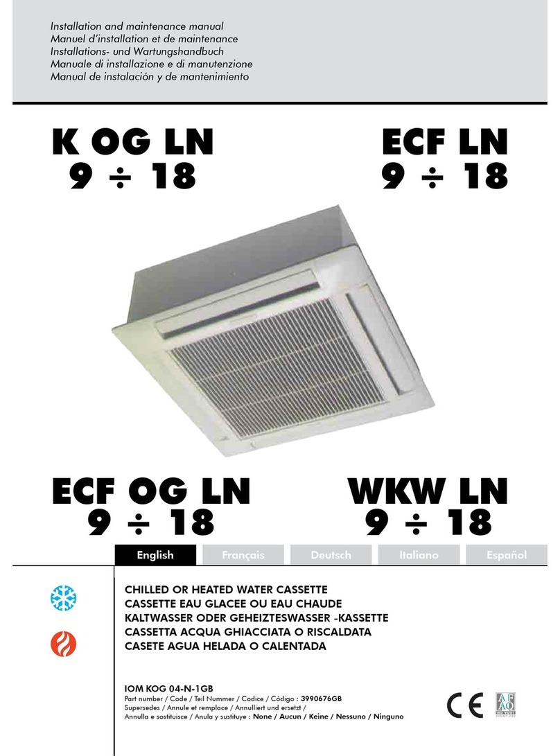
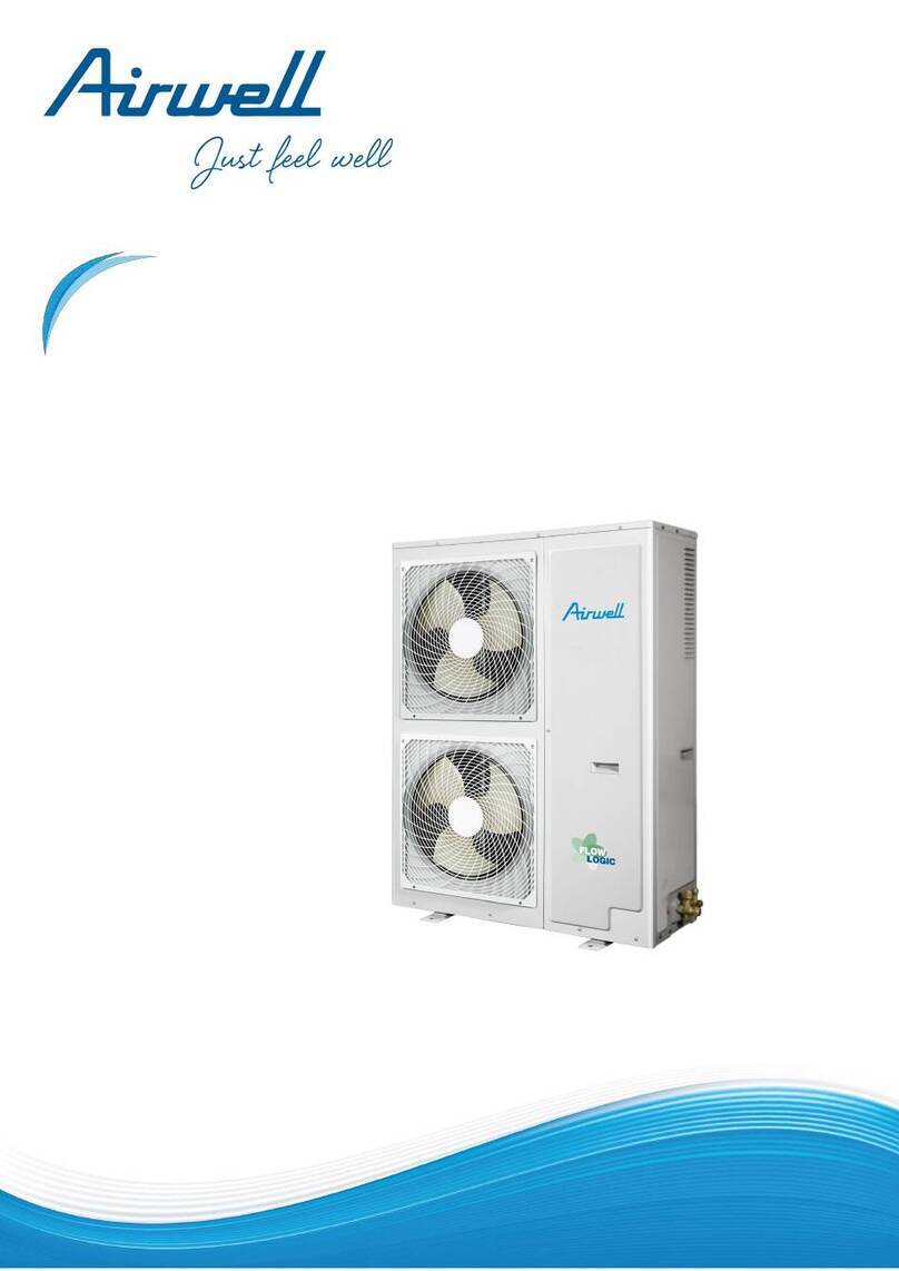
Split system gainable à pression -
Ductable pressurized split system -
Split-system für Kanalanschluß unter Druck
MISE HORS TENSION
OBLIGATOIRE AVANT
TOUTES INTERVENTIONS
DANS LES BOITIERS
ELECTRIQUES
- Les informations contenues dans cette notice sont
sujettes à modifications sans préavis.
ECOMMANDATIONS
GENERALES
- Avant tout, merci d'avoir porté votre choix
sur un matériel Airwell.
CONSEILS DE SECURITE
- Lorsque vous intervenez sur votre maté-
riel : suivez les règles de sécurité en vi-
gueur.
- L’installation et l’entretien du matériel de-
vront être effectués exclusivement par du
personnel qualifié selon les règles de l'art,
les normes et instructions en vigueur.
- Assurez-vous que l'alimentation électrique
disponible et la fréquence du réseau sont
adaptées au courant de fonctionnement né-
cessaire compte tenu des conditions spé-
cifiques de l’emplacement, et du courant
nécessaire à tout autre appareil branché
sur le même circuit.
AVERTISSEMENT
- Couper l'alimentation électrique générale
avant toute intervention ou opération d’en-
tretien.
- Le fabricant décline toute responsabilité et
la garantie ne sera plus valable si ces ins-
tructions d’installation ne sont pas respec-
tées.
- Si vous avez des difficultés, faites appel
au Service Technique de votre zone.
- Avant la mise en place, procédez si pos-
sible au montage des accessoires obliga-
toires ou non. (Voir notice livrée avec cha-
que accessoire) .
R
- Pour une meilleure connaissance du pro-
duit, nous vous conseillons de consulter
également notre notice technique .
ENERAL
RECOMMENDATIONS
- Congratulations for having selected an
Airwell air conditioner.
SAFETY DIRECTIONS
- Follow the safety rules in force when you
are working on your appliance.
- Installation and maintenance of the
equipment must only be performed by
qualified specialists in accordance with the
rules of good workmanship and prevailing
standards and instructions.
- Make sure that the power supply and its
frequency are adapted to the required
electric current of operation, taking into
account specific conditions of the location
and the current required for any other
appliance connected with the same circuit.
WARNING
- Cutoff power supply before starting to work
on the appliance.
- The manufacturer declines any
responsibility and the warranty becomes
void if these instructions are not respected.
- If you meet a problem, please call the
Technical Department of your area.
- If possible, assemble the mandatory or
optional accessories before placing the
appliance on its final location.(see instruc-
tions provided with each accessory)
In order to become fully familiar with the
appliance, we suggest to read also our
Technical Instructions .
- The information contained in these Instructions are
subject to modification without advance notice.
G
IT IS MANDATYORY TO
CUTOFF POWER SUPPLY
BEFORE STARTING TO
WORK IN THE ELECTRIC
CASING BOXES.
VOR JEDEM EINGRIFF IN
DEN SCHALTSCHRÄNKEN
UNBEDINGT NETZSTECKER
ZIEHEN
ALLGEMEINE
EMPFEHLUNGEN
-Zunächst danken wir Ihnen, daß Sie sich für
ein Airwell Klimagerät entschieden haben.
SICHERHEITSANWEISUNGEN
- Bei Eingriffen an Ihrem Gerät sind die
geltenden Sicherheitsvorschriften zu
befolgen.
- Installation und Wartung der Ausrüstung
dürfen nur von qualifiziertem Personal
fachgemäß und entsprechend den
geltenden Normen und Vorschriften
vorgenommen werden.
- Vergewissern Sie sich, daß
Stromversorgung und Netzfrequenz dem
erforderlichen Betriebsstrom entsprechen,
wobei die spezifischen Bedingungen des
Aufstellungsorts und der erforderliche Strom
für die anderen, an den gleichen Stromkreis
angeschlossenen Geräte zu berücksichtigen
sind.
WARNUNG
- Vor jedem Eingriff oder vor Wartungsarbeiten
an dem Gerät muß der Strom abgeschaltet
werden. Bei Nichtbefolgen dieser
Anweisungen lehnt der Hersteller jede
Verantwortung ab, und die Garantie wird
ungültig. Bei Schwierigkeiten wenden Sie
sich bitte an den für Ihren Bezirk
zuständigen Technischen Kundendienst.
- Vor dem Aufstellen falls möglich die
vorgeschriebenen oder wahlfreien
Zubehörteile montieren. (Siehe die mit den
jeweiligen Zubehörteilen gelieferte
Anleitung).
Um mit dem Gerät besser vertraut zu
werden, empfehlen wir, auch unsere
Technische Beschreibung durchzulesen.
-Die in der vorliegenden Beschreibung enthaltenen
Informationen können ohne vorherige Mitteilung geändert
werden.
