akira CT-21FD9M User manual

CONTENTS
1. SAFETY INSTRUCTIONS . . . . . . . . . . . . . . . . . . . . . . . . . . . 2
2. GENERAL INSTRUCTIONS . . . . . . . . . . . . . . . . . . . . . . . . . . 3
3. SPECIFICATIONS . . . . . . . . . . . . . . . . . . . . . . . . . . . . . . . . . 6
4. INSTRUCTION MANUAL . . . . . . . . . . . . . . . . . . . . . . . . . . . . 8
5.TROUBLESHOOTING . . . . . . . . . . . . . . . . . . . . . . . . . . . . . . 18
6. BLOCK DIAGRAM . . . . . . . . . . . . . . . . . . . . . . . . . . . . . . . . 24
7. THE METHOD OF ADJUSTMENT FOR CHASSIS . . . . . . . 25
8. IC DESCRIPTION . . . . . . . . . . . . . . . . . . . . . . . . . . . . . . . . . 29
9. EXPLODED VIEW . . . . . . . . . . . . . . . . . . . . . . . . . . . . . . . . 34
10. SCHEMETIC DIAGRAM . . . . . . . . . . . . . . . . . . . . . . . . . . . 35
11. PRINTED CIRCUIT BOARD . . . . . . . . . . . . . . . . . . . . . . . . 36
12. REPLACEMENT PARTS LIST . . . . . . . . . . . . . . . . . . . . . . 37
SERVICE MANUAL
H-704V CHASSIS

- 1 -
• SAFETY PRECAUTION
WARNING: Service should not be attempted by anyone unfamiliar with the necessary precaution an this
receiver. The following are the necessary precaution to be observed before servicing.
1. Always discharge the picture tube anode to the CRT conductive coating before handing the picture tube.
The picture tube is highly evacuated and if broken, glass fragments will be violently expelled. Use
shatterproof goggles and keep picture tube away from the body while handing.
2. When replacing chassis in the cabinet, always be certain that all the protective devices are put back in
place, such as; nonmetallic control knobs, insulating covers, shields, isolation resistor-capacitor network,
etc.
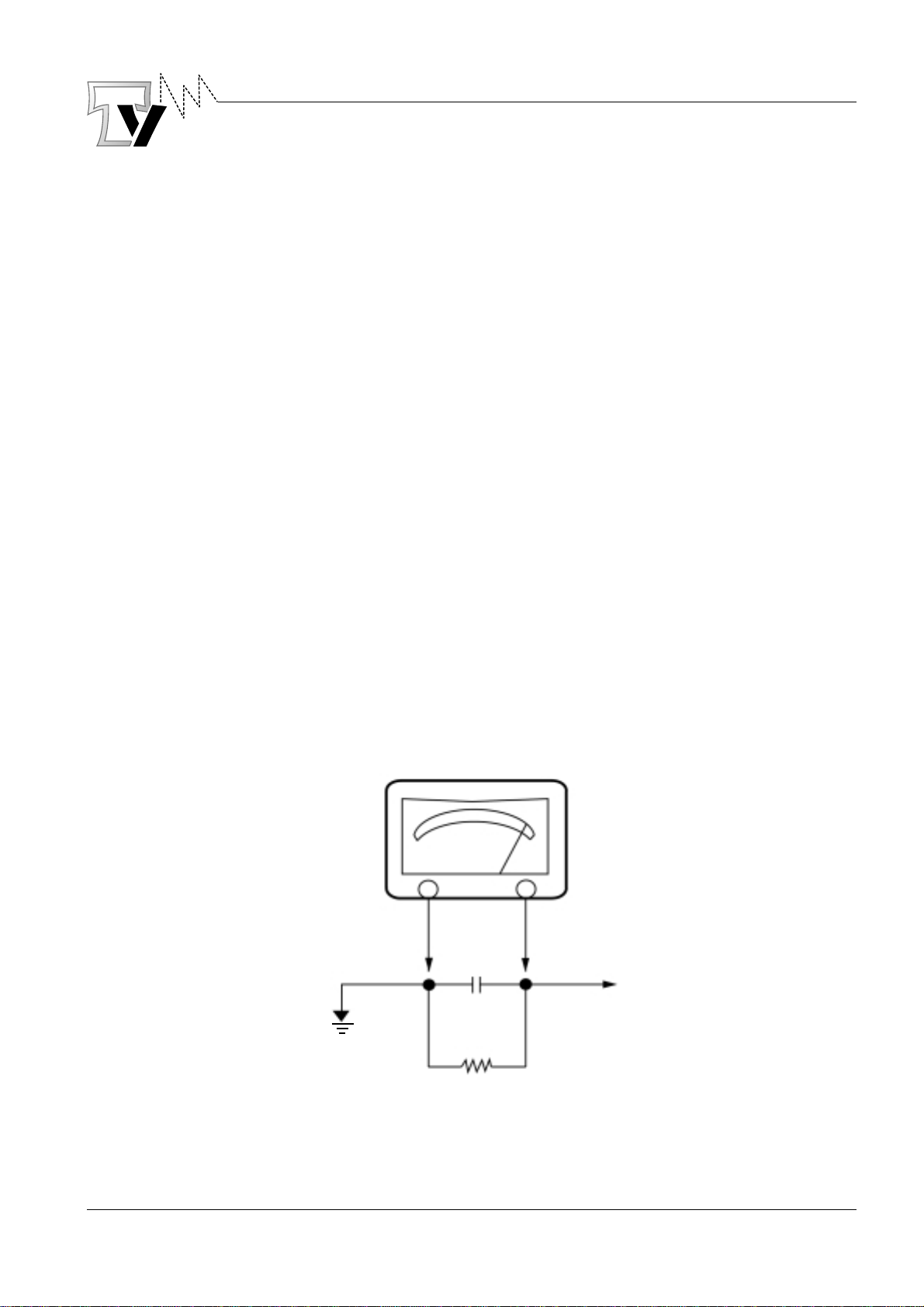
3. Before returning the set to the customer, always perform an AC leakage current check on the exposed
metallic parts of the cabinet, such as antennas, terminals, screw heads, metal overlays, control shafts etc.
to be sure the set is safe to operate without danger of electrical shock. Plug the AC line cord directly onto
a 110/220V AC outlet. Use an AC voltmeter having 500 ohms per volt or more sensitivity in the following
manner. Connect a 1500 ohm 10 watt resistor, paralleled by a 0.15 µF, AC type capacitor, between a
known good earth ground (water pipe, conduit etc.) and the exposed metallic parts, one at a time.
Measure the AC voltage across the combination of 1500 ohm resistor and 0.15 µF capacitor. Reverse the
AC plug at the AC outlet and repeat AC voltage measurements for each exposed metallic part. Voltage
measured must not exceed 0.3 volts RMS. This corresponds to 0.2 milliamp. AC Any value exceeding this
limit constitutes a potential shock hazard and must be corrected immediately.
AC VOLT METER
0.15 µF
1500 ohm
10 watt
Good earth ground
such as a water
pipe, conduit, etc. FIG 1
Place thes probe
on each exposed
metallic part

- 2 -
1. SAFETY INSTRUCTIONS
1-1 PRODUCT SAFETY NOTICE
Many electrical and mechanical parts in this chassis have special safety-related characteristics.
These characteristics are often passed unnoticed by a visual inspection and the protection afforded by
them cannot necessarily be obtained by using replacement components rated for higher voltage,
wattage, etc. Replacement parts which have these special safety characteristics are Identified in this
manual and its,
Supplements : Electrical components having such features are identified by shading on the schematic
diagram and the part list. Before replacing any of these components, read the parts list
in this manual carefully. The use of sub,situte replacement parts which do not have
same safety characteristics as specified in the parts list may create shock, fire or other
hazards.
1-2 SERVICE NOTES
1. When replacing parts or circuit boards, clamp the lead wires to terminals before soldering.
2. When replacing a high wattage resistor (metal oxide film resistor in the circuit .board) keep the
resistor min 1 /2inch away from the circuit board.
3. Keep wires away from high voltage or high temperature components.

- 3 -
2. GENERAL INSTRUCTIONS
2-1 CONVERGENCE MAGNET ASSEMBLY POSITIONING
Convergence magnet assembly and rubber wedges need mechanical positioning following figure 2.
2-2 COLOR-PURITY-ADJUSTMENT
NOTE : Before attempting any purity adjustments, the receiver should be operated for at least 15
minutes.
1. Demagnetize the picture tube and cabinet by using a degaussing coil.
2. Turn the CONTRAST and BRIGHTNESS controls to maximum.
3. Adjust RED and BLUE BIA, 5 controls to provide only a green rather.
4. Loosen the clamp screw holding the yoke, and slide the yoke backward to provide vertical green
belt(zone) in the picture screen.
5. Remote the Rubber Wedges.
6. Rotate and spread the tabs of the purity magnet(See figure 3) around the neck of the picture tube
until the green belt is in the center of the screen. At the same time, center the raster vertically.
7. Move the yoke slowly forward until a uniform green screen is obtained.
Tighten the clamp screw of the yoke temporarily.
8. Check the purity of the red and blue raster by adjusting the BIAS controls.
9. Obtain a white raster, referring to “CRT GRAY SCALE ADJUSTMENT”.
10. Proceed with convergence adjutment.
FIG. 2 Rubber Wedges Location

- 4 -
2-3 CONVERGENCE ADJUSTMENTS
NOTE : Before attempting any convergence adjutment, the receiver should be operated for at least 15
minutes.
2-3-1 CENTER CONVERGENCE ADJUSTMENT
1 .Receive a crosshatch pattern with a color bar signal generator.
2. Adjust the BRIGHTNESS and CONTRAST controls for a well defined pattern.
3. Adjust two tabs of the 4-pole Magnets to change the angle between them (See
figure 3)and superimpose red and blue vertical lines in the center area of the picture screen.
4. Turn both tabs at the same time keep in their angles constant to superimpose red and blue
horizontal lines at the center of the screen. (See figure 4).
5. Adjust two tabs of 6-Pole Magnets to superimpose red/blue line with green one.
Adjusting the angle affects the vertical lines and rotating both magnets affects the horizontal lines.
6. Repeat adjustment 3, 4, 5 Keeping in mind red. green and blue movement, because 4-Pole
Magnets and 6-Pole Magnets interact and make dot movement complex.
FIG. 3
FIG. 4

- 5 -
2-3-2 CONVERGENCE ADJUSTMENT
NOTE : This adjustment requires Rubber Wedge Kit.
1. Loosen the clamping screw of deflection yoke to allow the yoke to tiIt.
2. Place a wedge as shown in figure(2) temporartily.
(Do not remove cover paper on adhesive part of the wedge.)
3. Tilt the front of the deflection yoke up or down to obtain better convergence in circumference (See
figure 4) Push the mounted wedge into the space between picture tube arid the yoke to hold the
yoke temporarily.
4. Place other wedge into bottom space arid remove the cover paper to stick.
5. Tilt the front of the yoke right or left to obtain better convergence in circumference
(See figure 4.)
6. Hold the yoke position arid put another wedge in upper space, remove cover paper and stick the
wedges, recheck overall convergence .
7. Detach the temporarily mounted wedge and put it in another upper space.
Stick 2 on picture tube to fix the yoke.
8. After placing three wedges, recheck overall convergence.
Tighten the screw firmly to hold the yoke tightly in place.
9. Stick 3 adhesive tapes on wedges as shown in figure 2.

- 6 -
REMARKSPECIFICATIONITEM
3. SPECIFICATIONS
H-704V
VOLTAGE SYNTHESIZE (WITH REMOCON)
100 CHS
B/G, D/K,I, M(option)
PAL,SECAM, NTSC (option)
75 OHM ONLY ( UHF VHF 1 INPUT)
DIPOLE 700 3STEP
ELECTRONIC & VARACTOR
DT5-BF14D(DAEWOO), LG TUNER
L:S6~E2
H:S36~37
E69~S37
38.9MHz
DEPAND ON CCIR STANDARD
4.5(OPTION), 5.5, 6.0, 6.5MHz
F.M
AC 90-250V, 50/60Hz
CONTINENTAL PLUG
14" : 68[W] 20" : 75[W] 21" : 80[W]
NONE
AV 1,2 INPUT (RCA JACK)
MONITOR OUT (RCA JACK)
CATHODE RAY TUBE
5+5 WATTS MAX
8 OHM 5W(2EA)
1
GENERAL
2
ELECT-
RICAL
1) MODEL NO.
2) CHASSIS NO.
3)
TUNING
SYSTEM
1) CCIR STANDARD
2) COLOR STANDARD
3) ANT.
INPUT
4)
TUNER
5)
RECEPT10N
CHANNEL
6)
IF &
SUBCAR
RIER
7) SOUND TRANSMISSION
(DECODING) SYSTEM
8) MAINS
9) COUNTRY
10) SAFETY STANDARD
11) AUX
TERMIN-
AL
12)
DISPLAY
13)
AUDIO
1) METHOD
2) CHANNEL OF
PROGRAM
3) REMOTE
CONTROLLER
1) TERMINAL
2) ANTENNA
1) TYPE
2) PART NO
1) VHF
2) UHF
1) PIF
2) SIF
3) SOUND
SUBCARRIER
1) VOLTAGE &
FREQUENCY
2) CORD
3) POWER
CONSUMPTION
1) INPUT
2) OUTPUT
1) TYPE
2) SIZE
3) PART NO.
1) OUTPUT
POWER
2) SPEAKER

- 7 -
REMARKSPECIFICATIONITEM
- MENU
- CH UP
- CH DOWN
- VOL UP
- VOL DOWN
- TV/VIDEO SELECT
POWER 0-9
TV/AV/SAT(SAT:OPTION)
MUTE
CH UP SLEEP
CH DOWN FUZZY
VOL UP SOUND(STREO OPTION)
VOL DOWN DISPLAY
MENU QUICK VIEW
TIMER PICTURE
OK S-MENU(SAT OPTION)
STORE(SAT OPTION) SCREEN(SAT OPTION)
SCAN(SAT OPTION) SCREEN(SAT OPTION)
R,G,B,Y(TTX OPTION)
- NO SIGNAL AUTO POWER OFF ( AFTER 15
MINUTES )
- WHITE BALANCE CONTROL SERVICE KEY (FOR
FACTORY)
- LANGUAGE (MULTI)
- FUZZY PICTURE CONTROL
(NOMAL1, NOMAL2, FOVORITE)
- ON SCREEN DISPLAY
- 24 HOURS PROGRAMMABLE ON/OFF FUNCTION
- AUTO AGC CONTROL
- DC POWER(OPTION)
- RF/AV STEREO (OPTION)/NTSC
(EXCEPT RF STEREO)
- TTX(OPTION)
- SCART JACK
3.
USER
CONTR-
OL &
ACCES-
SORIES
4. SPECIAL NOTES
5. OPTION
1.
CONTROL 1) SET
2) REMOTE
CONTROLLER

- 8 -
4. INSTRUCTION MANUAL
To get the best satisfaction with your new COLOR TV SET, please read carefully and follow the instruction in
this guide.
We recommend that you read it before turning on your TV for the first time.
HOW TO GET THE BEST SATISFACTION
FROM YOUR NEW COLOR TV SET
INSTALLATION
ANTENNA
Unless your TV is connected to a cable TV system or to a centralized antenna system, a good outdoor color TV
antenna is recommended for the best performance. However, exceptionally, if you are in good signal area that is
free from interference of an electric wave, then an indoor antenna may be sufficient.
LOCATION(Ventilation)
Select an area where sunlight or bright indoor illumination will not fall directly on the TV screen. When you
place your COLOR TV, don’t forget to leave an interval of at least 10cm from the wall to prevent overheating.
POWER
Insert the power cord plug into 110/220, (100-240 Volts Automatic Voltage Regulator) 50/60 Hertz outlet.
Or, Insert the DC CAR cord plug into 9-13V outlet (option)
Please, Do not use DC power cord plug and AC power cord plug, together.
4-1. VHF ANTENNA or CABLE HOOK UP
At first, insert the lead of rod antenna into antenna adapter.
And connect antenna adapter to tuner jack. This antenna will provide an excellent picture in most areas. For the best
picture quality, adjust the length and position of antenna.
NOTE 1
If you don’t get good picture quality with an indoor antenna, an outdoor antenna is recommended. In this case
you should disconnect the indoor antenna before connecting an outdoor antenna to the TV.

- 9 -
MAKE REFERENCE TO THE BELOW THE PICTURE
ANTENNA JACK
75-300 OHM
COUPLING
TRANSFORMER
FROM 75OHM
ANTENNA
WITH CABLE OR
CABLE TV SYSTEM
ROD ANTENNA
TV SET OPERATION
Generally, REMOTE CONTROLLER has all the functions of the TV for normal use.
4-2. TO TURN ON/OFF THE TV SET
1-1 To turn on the TV, press MAIN POWER BUTTON on the front of TV, then
press any BUTTON on the PANEL or REMOTE CONTROLLER.
1-2 To turn off the TV, press POWER BUTTON on the PANEL or REMOTE
CONTROLLER.
4-3. TO SELECT CHANNEL
You can select the channels with CHANNEL NUMBER buttons or CHANNEL
UP/DOWN button.
4-3-1. TO SELECT CHANNEL DIRECTLY
Press the channel number you want with the number buttons. You can select 0~99 channels.

- 10 -
4-3-2. TO SCAN THROUGH CHANNELS
Press the CH UP/DOWN buttons on the PANEL or REMOTE CONTROLLER to find the channel you
want to see.
4-4. TO ADJUST VOLUME
To increase or decrease the volume, press the VOLUME UP/DOWN buttons on the PANEL or REMOTE
CONTROLLER.
4-5 OTHER FUNCTIONS
4-5-1 QUICK VIEW FUNCTION
If you want to go back to the previously viewed channel, press the QUICK VIEW
button.
4-5-2 SLEEP FUNCTION
Press the SLEEP button to set the timer from 30 to 120 minutes. Each time you
press the SLEEP button, changes of time as follows :
00 30 60
90120

- 11 -
Your TV will be turned off automatically after the set time.
The initial state of SLEEP mode is “ 00”, and the SLEEP FUNCTION does not operate in this state.
4-5-3 MUTE FUNCTION
MUTE button makes the sound off and displays an icon on the right top of the
screen.
Press the MUTE button again or press the VOL UP/DOWN buttons to restore
the sound.
4-5-4 TV/AV BUTTON FUNCTION
You can select TV and VIDEO mode.
To select VIDEO mode, press TV/AV button. The icon below will appear on
the right top of screen.
* STEREO MODEL (OPTION)
You can select TV, VIDEO 1 and VIDEO 2 mode.
To select VIDEO 1 mode, press TV/AV button once, and press twice for Video 2 mode. The icon below
will appear on the right top of the screen.
4-5-5 FUZZY FUNCTION
Users can select a combination of picture control. That includes a combination
of contrast, brightness, sharpness, color and tint.
These combinations are classified as three steps, Normal 1, Normal 2,
Favourite.
Each step will be selected by pressing FUZZY button on REMOTE
CONTROLLER.
4-5-6 DISPLAY FUNCTION
Press the DISPLAY button to see the current time and channel on the screen.
It lasts for four seconds. However, you can press again the DISPLAY button
to make the display disappear instantly.
Time display of this mode indicates the state of clock memory of TIMER of
MENU FUNCTION.
TV VIDEO TV
TV VIDEO 1 VIDEO 2 SVH(OPTION)
SAT(OPTION) TV
Normal 1 Normal 2 Favourite

- 12 -
4-6 MENU FUNCTION
If you press the MENU button, six items will
appear on the screen as following.
Press again the MENU button. Then the display
will return to the original screen.
4-6-1. PICTURE
1) Press Menu
2) Press CH UP/DOWN to select PICTURE item, and press O.K
3) Then, four items will appear as following on the screen.
4) Press CH UP/DOWN to select the item you want to adjust.
5) And press VOL UP/DOWN to adjust the item’s value.
6) To adjust other items, repeat step 4 and 5.
7) Press MENU to return to the MENU screen.
4-5-7. Timer FUNCTION
You can see the current time.
4-5-8. SOUND FUNCTION (STEREO MODEL ONLY)
You can select MONO, STEREO and DUAL 1, DUAL 2 by press the SOUND
button.
4-5-9. OK/DG BUTTON (DC POWER INPUT MODEL ONLY)
DC POWER INPUT MODEL BELOW FUNCTION ITEM ADD.
When the blue parts appear, you can clear the blue parts by press the OK key, but you can press the OK
button just one time during the one minute.
Main menu
Picture
Sound
Timer
Language
Preset
Edit
Activate OK
Sel. position
Exit MENU
Picture
Brightness 48
Contrast 58
Colour 55
Sharpness 39
Activate
Sel. position
Exit MENU

- 13 -
Equalizer : Higher resolution is possible in a gain step of about 1/8
dB. With positive equalizer settings, internal clipping may occur even
with overall volume less than 0 dB. This will lead to a clipped output
signal. Therefore, it is not remmended to set equalizer bands to a
value that, in conjunction with volume, would result in an overall
positive gain.
Audio in (Sound L, R divide mode) : When you use the audio out,
you selected STEREO or MONO mode
STEREO mode : Audio out divided L, R
MONO mode : Audio out L (You must hear sound L)
Equalizer
Activate
Sel. position
Exit MENU
15 15 15 15 15
120Hz 500Hz 1.5Hz 5KHz 10KHz
TINT item appears only when TV set receives the NTSC (play back only) signal.
4-6-2. SOUND (STEREO MODEL ONLY)
1) Press Menu
2) Press CH UP/DOWN to select SOUND item, and press O.K
3) Then, seven items appear as following on the screen.
4) Press CH UP/DOWN to select the item you want to adjust.
5) And press VOL UP/DOWN to adjust the item’s value.
6) To adjust other items, repeat steps 4 and 5.
7) Press MENU to return to the MENU screen.
ITEM Press VOL. DOWN (MIN 0) Press VOL. UP (MAX.63)
Brightness Darken the picture Brighten the picture.
Contrast Decrease picture contrast Increase picture contrast.
Colour Decrease shade of color Increase shade of color.
Sharpness Soften the picture. Sharpen the picture.
AVC : Press VOL. UP/DOWN, then OSD changes from OFF to ON.
You can hear different sound of many broadcasting stations as regular valued sound through this
function.
Sound
Bass 32
Treble 32
Balance
Effect OFF
Avc OFF
Equalizer OFF
Audio in STEREO
Activate
Sel. position
Exit MENU
ITEM Press VOL. DOWN Press VOL. UP
Bass Decrease the bass response. Increase the bass response.
Treble Decrease the treble response. Incresase the treble response.
Balance Emphasize the left speaker’s volume. Emphasize the right speaker’s volume.
Effect Effect OFF Effect ON
Avc Auto Volume Control OFF Auto Volume Control ON

- 14 -
4-6-3. TIMER
1) Press Menu
2) Press CH UP/DOWN to select TIMER item, and press OK button.
3) Then, five items appear as following on the screen.
4) Press CH DOWN to select the item you want to change.
5) Press OK to change the item’s time value.
6) Press the 0-9 buttons.
7) And press OK to set the time, you changed.
8) To change other items, repeat steps from 4 to 7.
9) Press MENU to return to the MENU screen.
ITEM Function
Clock To display or set up the present time.
Wake up time To turn your TV on at the set time.
Off timer To turn your TV off at the set time.
Activate Yes or No select by VOL.UP/DOWN
Wake up prog To turn your TV on at the set channel.
Timer
Clock --:--
Wake up time --:--
Off timer --:--
Activate Yes
Wake up prog P09
Activate OK 0..9
Sel. position
Exit MENU
4-6-4. LANGUAGE
* Select your language
1) Press Menu
2) Press CH UP/DOWN to select Language item, and press O.K
3) Then, nine languages appear as following on the screen.
4) Press CH UP/DOWN to select the language you want to use.
5) To change to other languages, repeat step 4.
6) Press MENU to return to the MENU screen.
Language
English
Français
Deutsch
Italiano
Espanol
Portugues
Persian
Russian
Arabic
Sel. position
Exit MENU

- 15 -
4-6-5. PRESET
1) Press Menu
2) Press CH UP/DOWN to select PRESET item, and press O.K
3) Then, items will appear as following on the screen.
4) Press VOL UP/DOWN to select the item you want to change.
5) Press CH UP/DOWN to change the item’s value.
6) To change other items, repeat step 4 and 5.
7) Press MENU to return to the MENU screen.
4-6-6. Edit
* Edit channel ( Memory Channel or Skip Channel)
1) Press Menu
2) Press CH UP/DOWN to select Edit item, and press O.K
3) Then, channels appear as following on the screen.
4) Press CH UP/DOWN to select the channel you want to change.
5) And press Yellow button to skip(YES: skip channel, NO : Memory channel).
6) To skip other channels, repeat step 4 and 5.
7) Press MENU to return to the MENU screen.
To change channel memory
1.Delete
To delete a channel from the memory, press the green button, and after a few seconds the selected channel
will be deleted from the list, and sent to the end of the list. The blank is automatically filled with the rest of
channels in order.
Sel. prog. 0..9.
Sel. position
Exit MENU
Preset
P09
----
B/G PAL
P --
(P09 : Select Channel)
Search
Auto. search OK
Sel. position
Exit MENU
( : Channel auto search)
Fine Tune
Sel. position
Exit MENU
( : Fine Tuning)
Sel. name
Input OK
Sel. position
Exit MENU
(–––– : Renaming the channel)
Sel. system
Sel. position
Exit MENU
(B/G : Select Sound)
You’ll see as following on the screen
B/G D/K I M (OPTION) B/G
Sel. system
Sel. position
Exit MENU
(PAL : Select Tuning system
PAL SCM NTSC(OPTION) PAL Sel. program No. 0..9.
Input OK
Sel. position
Exit MENU
(P–– :Memory Channel)

- 16 -
Sel. position
Move
Delete
Skip
Preset OK
Exit MENU
Edit
Pr Skip Pr Skip
00––––Yes 05––––Yes
01––––Yes 06 ––––Yes
02––––Yes 07––––Yes
03––––Yes 08––––Yes
04––––Yes 09––––Yes
2. Move
1) To move a memory channel to the other channel, press RED button.
Then you can see the color is changed from green to yellow on the
screen.
2) Select the other channel on the screen that you want to change by using
VOL.UP/DOWN and CH. UP/DOWN
3) Press RED button on the REMOTE CONTROLLER to move, and then
you can see the changed channel on the screen.
RED COLOR
GREEN COLOR
YELLOW COLOR
1) TV/TTX
This is toggle key, TV TELETEXT
When called in TV mode, this function activated TELETEXT
Initially page 100 of teletext will be displayed in the screen, unless at an earlier exit from TELETEXT (at the same
program), another page was requested in the page memory.
When called in TELETEXT sub mode, this command is interpreted as a rest
2) PAGE UP/DOWN
Page unmber is changed by “PAGE UP” or “PAGE DOWN” button or direct button (0-9).
3) INDEX
Press this key to select index page directly in FLOT and TV program in TOP mode.
4) SIZE
This is a toggle function between 3 different sizes.
Press “SIZE” button to expand the TOP half of the display.
Press again to expand the BOTTOM half of the display.
Press again to return the display to normal size.
5) SUB PAGE ACCESS
First, select the TELETEXT alarm page or TELETEXT page containing sub pages.
Press the “SUB” key, then four asterisks(“****”) will be displayed on the screen. Now enter the sub page number
required using keys “0-9” on the transmitter.
Press this key again to return to initial status.
TELETEXT FUNCTION (OPTION)

- 17 -
6) REVEAL
Press “REVEAL” key to reveal hidden words e.q. quiz pages will hidden answers.
Press the key again to make hidden words disappear.
7) HOLD
When TELETEXT information exceeds more than one page, the display changes automatically to the next page.
In rolling subpages, press “HOLD” button to hold the wanted display subpage.
And press the next button to stop the hold.
8) MIX
Press “MIX” button to superimpose TELETEXT picture into TV display.
Press this button again, then the screen go back to TELETEXT mode.
9) CANCEL
When searching for a TELETEXT page, the TV display can be viewed by pressing “CANCEL” key.
Once the page has been found, the page number will be displayed.
10) RED,GRE,YEL,CYN KEYS
These four keys are coloured-cord to correspond to the differently coloured subjects in “TTX” mode.
* press the menu
Adjust the volume and contrast in the MENU function
RED GREEN YELLOW CYAN

- 18 -
5. TROUBLESHOOTING
5-1. NO POWER (NOT WORKING SMPS)
CHECK THE VOLTAGE OF C804
CHECK THE VOLTAGE
AT PIN4 OF STR6653
CHECK/REPLACE
F801,D801,L801,R802
CHECK/REPLACE
R803,D802,R837
*R803A(ONLY DC)
CHECK/REPLACE
I801(STR6653)AND
THE SECONDARY PART OF POWER CIRCUIT
130 ~
380V
ABOUT 12V
0V
0V

- 19 -
CHECK IF HEATER ELEMENT IS LIGHTING
CHECK /REPLACE
R415
INCREASE THE SCREEN
VOLTAGE OF FBT
RETRACE LINE
IS VISIBLE
CHECK THE WAVEFORM
AT PIN42 OF I102
SCREEN IS BLACK
0V
NG
CHECK THE HEATER VOLTAGE
CHECK/REPLACE
Q401, Q402
CHECK THE WAVEFORM
AT PIN 10, 11, 12 OF I102
NO
CHECK/REPLACE
Q561, Q562, Q563
CHECK/REPLACE
I102
NO
YES
CHECK/REPLACE
T402(FBT)
SC562(CRT SOCKET)
5-2. NO RASTER & PICTURE
Table of contents
Other akira TV manuals

akira
akira 14KLS4/CE User manual

akira
akira CT-29FD9CPT User manual

akira
akira CT-21DS9A User manual

akira
akira CT-21LS9MTS User manual

akira
akira CT-14GT9A User manual

akira
akira LCT-20CHST User manual

akira
akira CT-21CBS5CPH User manual

akira
akira CT-14XA9A User manual

akira
akira CT-25TW9AN User manual

akira
akira LCT-20CVST User manual

akira
akira CT-25NI9AN User manual

akira
akira CT-21LPP1MKI/ANZ User manual

akira
akira 14LA/ANZ User manual

akira
akira 21SWP1/CE User manual

akira
akira CT-14TA9CP User manual

akira
akira 21RBS3 Series User manual

akira
akira CT-21FGS1 User manual

akira
akira CT-21CQS5CPT User manual

akira
akira CT-21CDP5CP User manual

akira
akira CT-25XG9 Series User manual