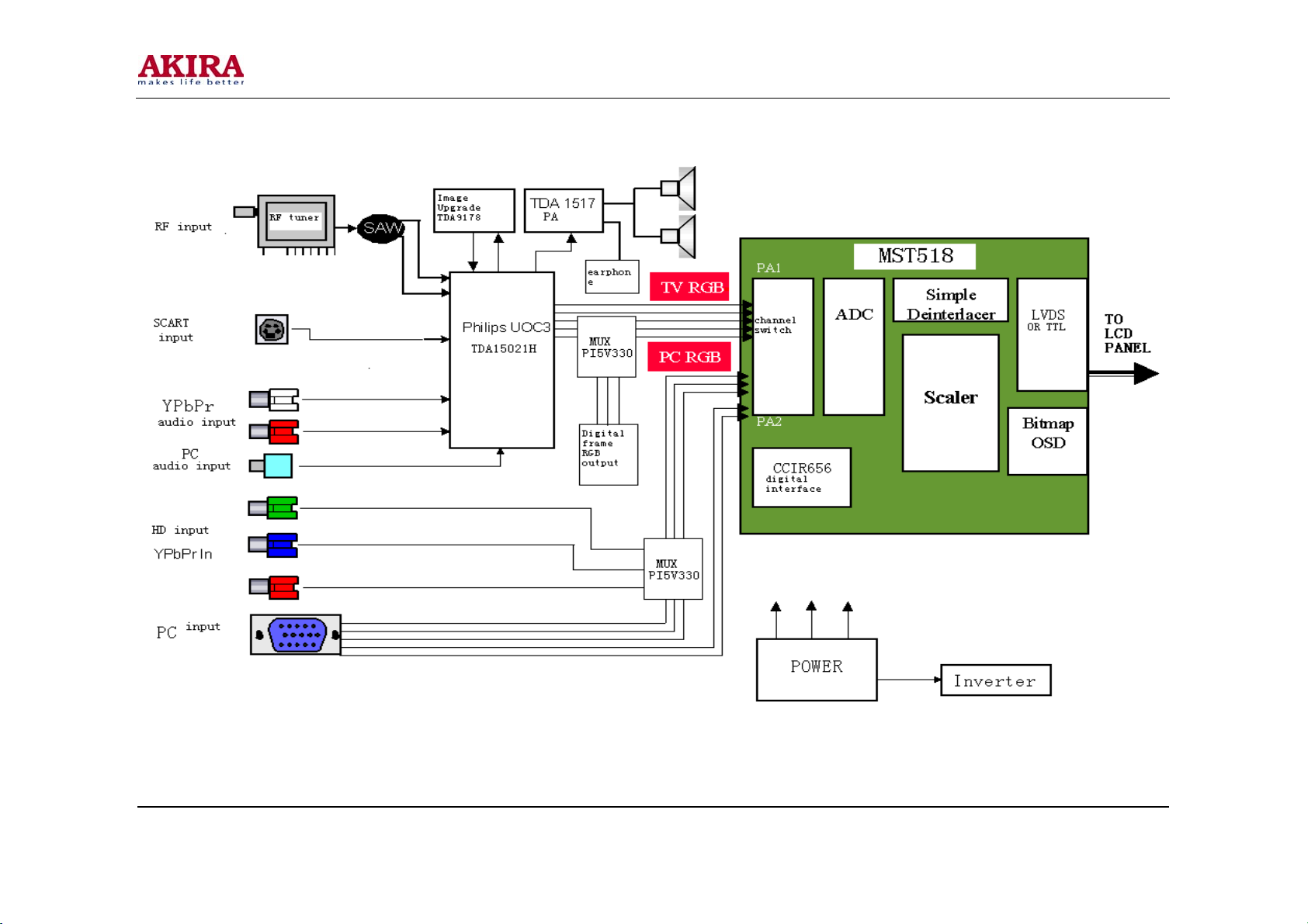
akira LCT-20CHST User manual

LCT TV
Service Manual

-2-
Model No.: LCT-20CHST
Version: 1.0
M
M
Mo
o
od
d
de
e
el
l
l:
:
:
L
L
LC
C
CT
T
T-
-
-2
2
20
0
0C
C
CH
H
HS
S
ST
T
T
C
C
Ch
h
ha
a
as
s
ss
s
si
i
is
s
s:
:
:
L
L
LS
S
S-
-
-0
0
07
7
7

-3-
Model No.: LCT-20CHST
Version: 1.0
CONTENTS
SPECIFICATION AND FEATURE ......................................................................................................... 4
THE FUNCTION INTRODUCTION LS07 CHASSIS LCD TV’S MAIN............................................. 9
SIGNAL PROCESSING FLOWCHART............................................................................................... 22
SPARE PART LIST AND EASY DAMAGE PART LIST ..................................................................... 34
FACTORY MODE ................................................................................................................................. 36
CIRCUIT DIAGRAM ............................................................................................................................ 37
WIRING DIAGRAM ............................................................................................................................. 47
EXPLODED VIEW................................................................................................................................ 48
PART LIST ............................................................................................................................................. 49

-4-
Model No.: LCT-20CHST
Version: 1.0
SPECIFICATION AND FEATURE
1. The Technical Specification of F Series Europe LCD TV:
a. TM150F7E:
Max display format: 1024*768(XGA)
Audio power output: 2*2.0W
Voltage: DC12V
Power adapter voltage: AC 100~240W,50/60HZ
Power adapter Model number: FSP048-1AD101C
b. W170F7E:
Max display format: 1280*768(WXGA)
Audio power output: 2*2.0W
AC input voltage of inside power Mold piece: AC 100~240V, 50/60HZ
The unit sets: AC power Switch.
c. TM201F7E:
Max display format: 640*480(VGA)
Audio power output :2*2.0W
AC input voltage of inside power mold piece: AC 100~240V, 50/60HZ
The unit sets: AC power Switch.
2. Main feature
a. RF input , CATV function
Can receive 470MHZ CATV Programs, can store 100 programs
(Program number display 0~99);
b. AV Audio and AV Video input
In scart mode, the system can automatically activate scart checking function to identify
signal input modes (CVBS or RGB) and input signal character (16:9 or 4:3); Capable to
receive PAL, NTSC, SECAM color systems; Very convenient to watch VCR (video cassette
recorder), Pickup Camera and other Disc’s programs.
c. YPbPr input
Can receive high definition YPbPr component video signal from such as DVD Conveniently .
Support format: 480I, 480P, 576I, 576P, 720P (50/60HZ), 1080I (50/60HZ), 1080P
(50/60HZ);
d. VGA input
As the Terminal display Equipments of computer, it can connect with computer conveniently.
It can connect with Computer audio card by its own Audio connection line ,so you can listen
the audio information from computer.

-5-
Model No.: LCT-20CHST
Version: 1.0
e. Program lock and child lock function
The function of program lock can lock the programs, input password and modification, the
function of child lock can lock the keys.
f. Timer function
You can set turn on and turn off on time, and power off in 15 min automatically if no signal
input. Automatically enter into save energy mode by itself if no signal in PC condition, it can
be awaken if signal inputs.
g. Blue screen mute noise
In condition of TV, AV, RGB and YPbPr, gentle blue screen will be displayed if no signal
input.
h. Chinese/English menu
Adopt the design of Convenient and Simple graphic menu, you can operate menu more
conveniently and more intuition.
i. Save energy function (power management mode)
When TV is used as PC display terminal, and PC has no output signal . The TV will be power
off in about 30 Seconds automatically, and enter into standby condition. press down
Power/P+/P-/ Number key of Remote control or the PC signal appearance again, the TV will
be on automatically.
j. Plug and play
The TV works as the terminal Equipments of computer, need not equip install software,it is
real Plug-and-Play.
k. Automatic correct
By its automatic correct function, the LCD TV can bring you the best view.
l. No Flicker, no radiation, green environment protection
The LCD TV can bring you high quality view, and avoid radiation, protect your eyes and look
after your health.
m. Because of it’s advanced power management mode, the TV can realize standby and recall on
function.
n. ACI function (Auto channel Installation).
o. Stereo and digital accompanying sound processing.
Auto identify and demodulate IGR, and decode NICAM digital accompanying sound.
p. Zoom image function
Support follow zoom function: Full screen mode, 4:3 mode (16:9 TFT), 16:9 (4: 3 TFT),
Movie mode, Sub-title movie mode.
q. Light weight, small dimension, low power consumption

-6-
Model No.: LCT-20CHST
Version: 1.0
r. Advanced picture quality Strengthen function
Dynamic skin color Correct: Improve distort color in picture make it Near to real color.
Black level Extension: blacken the more black area of picture. Raise the contrast in Dark
Background.
Color Edge correct: Increase the Steep of color signal edge make the edge of color Transition
more clearly.
Brightness edge correct: increase the steep of Brightness signal edge make the edge of picture
is more clearly.
s. Super fine and inner fairness TFT
t. 10-page teletext storage
u. Dynamic comb filter
v. Headphones output
3. Electric circuit of the TV
The Europe LS07 chassis LCD TV is composed of Steady voltage circuit、inverter Circuit, RF
circuit, video Strengthen circuit, video Processing circuit, Power Enlarge circuit, VGA circuit,
system control circuit and key control circuit. The block diagraph of circuit Constitute is below:

-7-
Model No.: LCT-20CHST
Version: 1.0

-8-
Model No.: LCT-20CHST
Version: 1.0
4. PCB Module introduction
The Constitute of the PCB is easier than LP03 chassis, all the Signal Processing are in Main board.
a. Main board Module
Main board Module is the main part of Signal Processing in LCD TV. The input signal is
converted into uniform digital signal, which can be identified by LCM by system control
circuit. Main board module contain two parts of signal processing Module: Philips UOC3
process analog audio and video circuit mainly, MST518 process VGA circuit, signal Format
transform system control circuit mainly. The front module can convert the video IF signal and
audio IF signal from tuner into RGB analog signal and audio signal, this part is named analog
audio and video decoding process. The RGB color from UOC is received by MST518 and
accomplishes A/D conversion, output suitable digital color signal to drive circuit of TFT. 8051
Processor inside UOC is responsible for co-operation the each part of works in system, and
Respond to user operation, which is operated on Control panel (key-press panel Module).
b. Key board Module
It is composed of 7 function keys the user can operate the LCD TV conveniently by using this
Module.
c. Remote control receiving board Module
It is composed of a work indicator light and a remote receive head. The user use the remote
control box by this module can operate the LCD TV conveniently and know the LCD TV
work condition.
d. Earphone output board module
It is composed of a earphone outlet, user can Listen to by earphone conveniently.
e. Inverter board module (include inverter circuit)
The function of the inverter is supply power to light tube in TFT and lighten the back lamp
Unit of TFT module, so the user can see the image on TFT.

-9-
Model No.: LCT-20CHST
Version: 1.0
THE FUNCTION INTRODUCTION LS07 CHASSIS LCD
TV’S MAIN IC
1. The main IC of LS07 chassis
Number Name Model Main function
1 A1 TAF5-E2I21RW2 RF tuner
2 U8, U21 TDA1517AWT Audio amplifier
3 U3 MST518 AD converter and format change
4 U2 UOC(TDA15021H) Video decode and MCU control
5 Q9 Si2311DS MOS switch
6 U11, U12 IRF7316 MOS switch
7 U19 NTMS10P02 MOS switch
8 U23 LM2596-5.0 Liner voltage IC
9 U1
24LC21A EEPROM (save display parameter
information)
10 U4 24LC32A EEPROM(save user control information)
11 U6, U20 PI5V330A Video switch
2. The function introduction of main IC
a. MST518 high integration chip
MST518 is a high performance, high integration image processor which is designed for LCD,
it can support SXGA format (1280*1024).it integrates a group of AD converter, high quality
format transform system, OSD generator, output clock generator, multiple format output
display interface (support TTL, LVDS, RSDS)
MST518 feature:
Have high quality Expand transform and compress transform, can output XGA format
signal
Integrated LVDS circuit inside
8 bit high quality ADC inside
Double VGA input, Software switch
Support ITU-656 format signal input
Support H/V sync, composite sync, green composite sync input, and detect
automatically by itself
Programmable 10 bit Gamma correct, the brightness and contrast is adjustable
8 color, 256 Character OSD
Built-in DDC circuit inside
Low standby power
Support TTL, double LVDS signal output, Software switch

-10 -
Model No.: LCT-20CHST
Version: 1.0
MST518 pin function:
And CPU interface
Pin Pin name Pin function
33 HWRESET
Hardware reset,high voltage enable
82 CS Chip select signal of three-wire serial bus
83 SDA data signal of three-wire serial bus
84 SCL clock signal of three-wire serial bus
85 INT interrupt
98-91 AD [7:0]
Parallel bus,the chassis is not used
125 BUSTYPE Bus type select
Analog Interface
38 HSYNC0 Analog Horizontal sync signal input channel 0
39 VSYNC0 Analog vertical sync signal input channel 0
40 HSYNC1 Analog Horizontal sync signal input channel 1
41 VSYNC1 Analog vertical sync signal input channel 1
78 RMID Scaler internal reference voltage
79 REFP
internal ADC decouple +
80 REFM
internal ADC decouple -
75 RIN0 Analog red signal input channel 0
74 RIN0M Analog red signal input channel 0 regrounding voltage
73 SOGIN0 Green sync signal input channel 0
72 GIN0 Analog green signal input channel 0
71 GIN0M Analog green signal input channel 0 regrounding
voltage
70 BIN0 Analog blue signal input channel 0
69 BIN0M Analog blue signal input channel 0 regrounding voltage
66 RIN1M Analog red signal input channel 1 regrounding voltage
65 RIN1 Analog red signal input channel 1
64 GIN1M Analog green signal input channel 1 regrounding
voltage
63 GIN1 Analog green signal input channel 1
62 SOGIN1 Green sync signal input channel 1
61 BIN1M Analog blue signal input channel 1 regrounding voltage
60 BIN1 Analog blue signal input channel 1
55 REXT Outside connect 390with 3.3V

-11 -
Model No.: LCT-20CHST
Version: 1.0
LCD Interface
145 OCLK Clock output
146 LDE Enable signal
144 LVSYNC Vertical sync output
143 LHSYNC Horizontal sync output
138 LVA0M
LVDS output 0-
137 LVA0P LVDS ouput 0+
136 LVA1M
LVDS output 1-
135 LVA1P LVDS ouput 1+
134 LVA2M
LVDS ouput 2-
133 LVA2P LVDS output 2+
128 LVA3M
LVDS output 3-
127 LVA3P LVDS ouput 3+
132 LVACKM
LVDS clock signal ouput-
131 LVACKP LVDS clock signal ouput +
26-23,18-15 RB[7:0] TTL red signal channel
14-11, 8-5 GB[7:0] TTL green signal channel
4,3,154,153,150-147 BB[7:0] TTL blue signal channel
GPIO Interface
87 GOUT1/PWM1 PWM output 1
86 GOUT0/PWM0 PWM output 0
2 BYPASS Outside connect filter capacitor
29 DDC_DAT Analog interface DDC data
30 DDC_CLK Analog interface DDC clock
31 DDCROM_CLK DDC ROM clock
32 DDCROM_DAT DDC ROM data
34 XIN Crystal oscillator signal input
35 XOUT Crystal oscillator signal output
Power Pins
48, 54, 58, 77 AVDD A/D convert power supply
56 AVDD_PLL PLL power supply
36 AVDD_MPLL MPLL power supply
10, 22, 88, 99, 111,
129, 139, 151 VDDP Digital signal output power supply
19, 102, 114, 142 VDDC Digital circuit power supply
1, 9, 20, 21, 37, 42,
45, 51, 57, 59, 76,
81, 89, 100, 101,
112, 113, 130, 140,
141, 152
GND Digital circuit ground

-12 -
Model No.: LCT-20CHST
Version: 1.0
MST518 inner diagraph:
b. TDA15021H introduction:
The third-generator super integrated circuit UOC III which designed by Philips company
recently integrates with video decode, 2D comb filter, high quality audio transacting
technique, suitable with the European teletext technique and suitable with US closed caption
and V-chip function compatible with single series IC. The series of UOC III have high
integrity, besides completing the Processing of all small signals (IF signal demodulation,
video decode, H/V signal, sound DSP), and integrate all the MCU function. It has many
Advantages, example: the compact circuit, good performance, simple craft and etc. It
matched with company’s high performance price ratio and high product efficiency
demanding. It is suitable for 4:3 or 16:9, 50/60HZ and A100/120HZ TV system, the main
characteristic below:
Multi-system IF demodulation、analog video decode
Comb filter internal
NICAM, stereo auto identify and decode
SCART input channel source auto identify (RGB, CVBS), SCART image input format
identify (4:3, 16: 9)
Support 4:3, 16:9 display format
TOP/FLOF TELETEXT (10 page) receive display
Channel auto install ACI function (can preset)
4 CVBS or 3 Y/C input, 1 CVBS output, 2 YcrCb/2 RGB input
4 AV audio input, 1 AV adjustable audio volume output
Volume auto level control circuit
Global FM demodulation
Picture quality enhancement of dynamic peak value control, skin color correct, Gamma
correct, Black level extension.

-13 -
Model No.: LCT-20CHST
Version: 1.0
Can turn down horizon and vertical scan part output H/V sync signal to Scaler
128K Flash Memory inside, support program on line
Automatic Y/C signal identify
TDA15021H pin function:
Pin Pin name Pin function
1 VSSP2 Grounding
2 VSSC4 Grounding
3 VDDC4 +1.8V
4 VDDA3 +3.3V
5 VREF_POS_LSL +3.3V
6 VREF_NEG_LSL+HPL 0V
7 VREF_POS_LSR+HPR +3.3V
8 VREF_NEG_HPL+HPR 0V
9 VREF_POS_HPR +3.3V
10 XTALIN Crystal oscillator input
11 XTALOUT Crystal oscillator output
12 VSSA1 Grounding
13 VGUARD/SWIO Protecting voltage input or I/O
14 DECDIG DECDIG signal input
15 VP1 +5V
16 PH2LF The second grade horizontal phase lock filter
17 PH1LF The first grade horizontal phase lock filter
18 GND1 Grounding
19 SECPLL SECAM PLL decouple
20 DECBG Inside reference voltage decouple
21 EWD/AVL VDD5A voltage input
22 VDRB Tv vertical sync signal output
23 VDRA Vertical sync output
24 VIFIN1 VIFinput 1
25 VIFIN2 VIFinput 2
26 VSC Outside connect vertical ramp capacity
27 IREF Recurrent input
28 GNDIF IF grounding
29 SIFIN1 SIF input 1
30 SIFIN2 SIF input 2
31 AGCOUT Tuner RF AGC control voltage output

-14 -
Model No.: LCT-20CHST
Version: 1.0
32 EHTO Over voltage protection input
33 SSIF MUTE control signal input
34 AUDIOIN5L Av left track signal input
35 AUDIOIN5R Av right track signal input
36 AUDOUTSL SCART/CINCH left track output
37 AUDOUTSR SCART/CINCH right track output
38 DECSDEM Track demodulator decouple
39 QSSO De emphasis capacitor
40 GND2 Grounding
41 PLLIF IF_PLL filter
42 SIFAGC Sound intermediate frequency auto gain control
43 IFVO IF demodulation video output
44 FMRO Fm broadcast output
45 VCC8V The supply voltage of Sound switch
46 AGC2SIF The second sound intermediate frequency auto gain
control
47 VP2 +5V
48 IFVO The video output of Choose channel
49 AUDIOIN4L HD signal left track audio output
50 AUDIOIN4R HD signal right track audio output
51 CVBS4/Y4 S-video luminance signal input
52 C4 S-video chroma signal input
53 AUDIOIN2L PC signal left track audio input
54 AUDIOIN2R PC signal right track audio input
55 CVBS2/Y2 AV CVBS signal input
56 AUDIOIN3L Inside DVD module left track audio input
57 AUDIOIN3R Inside DVD module right track audio input
58 CVBS3/Y3 Inside DVD module brightness signal input
59 C2/C3 Inside DVD module chroma signal input
60 AUDOUTLSL Main channel left track output
61 AUDOUTLSR Main channel right track output
62 AUDOUTHPL Earphone channel left track output
63 AUDOUTHPR Earphone channel right track output
64 CVBS/PIP CVBS/PIP output
65 SVM Scan modulate output
66 FBISO Flyback input/sandcastle output or composite H/V
timing output
67 HOUT Horizontal sync signal output

-15 -
Model No.: LCT-20CHST
Version: 1.0
68 VSScomb Grounding
69 VDDcomb +5V
70 VIN V signal input
71 UIN U signal input
72 YIN Y signal input
73 YSYNC Y signal input for Sync separate
74 YOUT Y signal output
75 UOUT U signal output
76 VOUT V signal output
77 INSSW3 RGB/YpbPr insert identify signal input
78 R/PrIN3 R/Pr signal input
79 G/YIN3 G/Y signal input
80 B/PbIN3 B/Pb signal input
81 GND3 Grounding
82 VP3 +5V
83 BCLIN Beam current limiter input
84 BLKIN Black current input
85 RO R basic color signal input
86 GO G basic color signal output
87 BO B basic color signal output
88 VDD3 +3.3V
89 VREFAD_NEG 0V
90 VREFAD_POS +3.3V
91 VREFAD Audio ADC re.voltage
92 GNDA Grounding
93 VDDA +1.8V
94 VDD3A +3.3V
95 VSSADC Grounding
96 VADC +1.8V
97 INT0 Remote control signal input
98 P10/INT1 DPF clock line
99 P11/T0 DPFdata line
100 VDDC2 +1.8V
101 VSSC2 Grounding
102 P04/12SWS MST reset signal
103 P03/12SCLK HD Pc select control signal
104 P02/12SDO2 Power Amplifier standby control signal
105 P01/12SDO1 TV_DPF select control signal

-16 -
Model No.: LCT-20CHST
Version: 1.0
106 P00/12SDII/O Turn on control signal
107 P13/T1 MST chip select signal
108 P16/SCL UOCI2C bus clock line
109 P17/SDA UOCI2C bus data line
110 VDDP +3.3V
111 P20/TPWM Red indicator light control signal
112 P21/PWM0 Green indicator light control signal
113 P22/PWM1 TFT power supply control signal
114 P23/PWM2 Inside DVD module power supply control signal
115 P30/ADC0 Reserve IO port
116 P31/ADC1 Earphone insert identify signal input
117 VDDC1 +1.8V
118 VDD18 +1.8V
119 P32/ADC2 DVD key-press signal input
120 P33/ADC3 TV key-press signal input
121 VSSC Grounding
122 P24/PWM3 Background control signal output
123 P25/PWM4 SAW filter control signal
124 VDDC3 +1.8V
125 VSSC3 Grounding
126 P12/INT2 MST interrupt signal input
127 P14/RX MST data line
128 P15/TX MST clock line

-17 -
Model No.: LCT-20CHST
Version: 1.0
TDA15021H inside block diagram

-18 -
Model No.: LCT-20CHST
Version: 1.0
c. TDA9178 introduction
TDA9178 is a analog signal processor with standard YUV input and output interface .It provid
three main process function: luminance vector, color vector and spectrum process. It can finish
comprehensive picture improving function independently. The characteristics of the TDA9178 are
below:
Luminance Transient Improvement (LTI), Colour Transient Improvement (CTI)
Variable gamma control
Self-suitable black level extend control
Skin color correction, green intensity ,blue extend
Noise measurement and reduced noise process founction
Line Width Control (LWC)
TDA9178 PIN DESCRIPTION:
Pin Pin name Function
1 Sand castle input Sand castle input
2 Not connected Grounding
3 ADC input 1 A/D convertor input 1
4 ADC input 2 A/D convertor input 2
5 ADC input 3 A/D convertor input 3
6 Luminance input Y input
7 Address selection input I2C address choose input port
8 U signal input U input
9 V signal input V input
10 Test pin Grounding
11 Serial clock input (I2C-bus) I2C bus clock signal
12 Not connected Not connected
13 Not connected Not connected
14 Serial data input/output (I2C-bus) I2C bus data signal
15 Decoupling digital supply Connect decouple capacitor external
16 V signal output V signal output
17 U signal output U signal output
18 Ground Ground
19 Luminance output Y signal input
20 Supply voltage Supply power
21 SCAVEM output Scan velocity modulate output
23 Not connected Grounding
24 Not connected Grounding

-19 -
Model No.: LCT-20CHST
Version: 1.0
TDA9178 inside block diagram:

-20 -
Model No.: LCT-20CHST
Version: 1.0
d. TDA1517AWT brief:
The TDA1517ATW is a double channel class-AB power amplifier contained in a plastic heat
sink thin shrink small outline package (HTSSOP20). The device is primarily developed for
multimedia applications.
• Outside circuit is simple
• Mute, standby is controllable
• Temperature protect circuit
• Low noise switch
• Constant gain
TDA1517 PIN DESCRIPTION:
Pin Pin name function
3 Non-inverting input Audio input
5 Supply voltage ripple rejection Bias circuit filter
8, 9 Output Audio output
12, 13 N.C. Not connected
15, 16 Supply voltage +12V power supply
17 Mode select switch Work mode select
18 Inverting input Reverse input terminal (connect capacitor to
ground )
1, 2, 4, 6, 7, 10,
11, 14, 19, 20
GND Ground
Table of contents
Other akira TV manuals

akira
akira CT-29TP9AS User manual

akira
akira CT-21CQS5CPT User manual

akira
akira CT-21TF9 User manual

akira
akira CT-21CH9 User manual

akira
akira 14THS3/CE User manual

akira
akira CT-29DR9 Series User manual

akira
akira CT-21PX9R User manual

akira
akira 21SWS1 BN User manual

akira
akira CT-21NI9 User manual

akira
akira 14FES1/BE User manual

akira
akira CT-14XA9A User manual

akira
akira CT-21LS9MTS User manual

akira
akira 21WHS3 User manual

akira
akira CT-21FD9M User manual

akira
akira 14BM19 User manual

akira
akira CT-14AZ9CP User manual

akira
akira 21FS9 Series User manual

akira
akira 14RBS3WN User manual

akira
akira CT29AZ9 Series User manual

akira
akira CT-21FDS1 User manual