akpo WK-7 User manual

1
MANUAL
KITCHEN HOOD WK-7
ENG
Manufacturer:
Production and trading enterprise
“AKPO” Spółka jawna
05-080 Izabelin-Laski; ul. Łąkowa 10
www.akpo.pl
Production plant:
06-430 Sońsk; ul. Ciechanowska 26
phone: (0-23) 671-34-70
fax: (0-23) 671-34-72

2
Dear customers!
Congratulations on your choice. Our equipment is designed and
manufactured to meet your expectations and will certainly become part of
a kitchen equipped in a modern manner. We are convinced that modern,
functional and practical devices made from high-quality materials will
meet all your requirements.
Before installing and using the hood, please read the contents of this
manual and the safety rules. We wish you satisfaction from using our
hoods.
1. GENERAL INFORMATION
The hood type WK-7 is designed to remove kitchen fumes in the outlet mode (pipelines
go outside the room) or in the absorption mode (internal circulation). It is designed to be
installed above a gas or electric stove. It has its own lighting and exhaust turbine with a
choice of one of three speeds of operation.
Note:
Save the purchase receipt along with a stamped warranty card for a potential complaint.
Without these documents, the warranty is void.
The manufacturer shall not liable for damages or damages caused in connection with
installation and use not in accordance with the instructions contained in this manual.
2. INSTALLATION
2.1 SETTING THE HOOD OPERATION MODE
The hood WK-7 can operate in two modes:
1) Outlet (Fig. 4a) - air is removed outside the room through the connection of the exhaust
hood to the ventilation pipe using a rigid plastic pipe with a diameter of 120 mm

3
2) Absorption (Fig.4b) - internal air circulation through a carbon filter (Fig. 3).
Fig.1 Fig.2 Fig.3
Filtered air is returned through the front outlet. Carbon filters should be changed at least
once every 3 months (depending on the intensity of cooking).
If the hood is installed as a vent, a check valve should be installed (Fig. 2), with two
folding valves that prevent the return of air from the ventilation pipe. On the check valve
there is an installed pipe for air exhaust.
a) OUTLET b)ABSORBER
P3050/60, K50/60 Light
Fig. 4
ATTENTION:
The air from the eaves should not be discharged to the chimney used to evacuate gases from
gas burning appliances or other fuels.
The hood has two outlets. On the top of the eaves and on the back of the eaves.

4
Depending on the needs, the user can use one of two options to connect the hood as a
statement:
1) Outlet from the top - on the upper opening of the hood, we install a collar Ø 120 mm with
a non-return valve (Fig. 5)
Fig. 5
2) Outlet at the back - in the rear opening of the hood there are two wings, which should be
cut from the bottom (Fig. 6). In order to facilitate removing of the air curtain, cut the curtain
with a knife across the center (Fig. 7) and remove it through the upper hole (Fig. 8)
Then put the end cap on the upper hole (Fig. 9).

5
Fig. 6
Fig. 7
Fig. 8

6
Fig. 9
In order to connect the hood as an absorber, unscrew the curtain of the front outlet (Fig.9)
and remove it from the turbine (Fig.10). Then cut the curtain with scissors (along the
groove) (Fig.11 and Fig.12). The cut curtain must be placed into the hood turbine and
screwed on again (Fig.13 and Fig.14). Put the end plug on the upper outlet (Fig. 15); the
cleaned air is ejected through the front outlet openings of the hood.
ATTENTION:
If the hood is supposed to work as an absorber, do not remove
the air curtain used as the rear air outlet.

7
Fig. 10
Fig. 11

8
Fig. 12
Fig. 13

9
Fig. 14
Fig. 15

10
2.2 ELECTRICAL CONNECTION
Before connecting the hood to electricity, make sure that the voltage and frequency of
the power supply correspond to the data indicated on the instrument panel. The hood
must be connected to an easily accessible outlet. Removing the plug and connecting the
hood directly to electricity is unacceptable. The hood should be connected to electricity
after installation as indicated.
3. INSTALLATION
For a gas stove, the distance “A” between the lowest part of the hood and the cooking
surface must be at least 65 cm (Fig. 16).
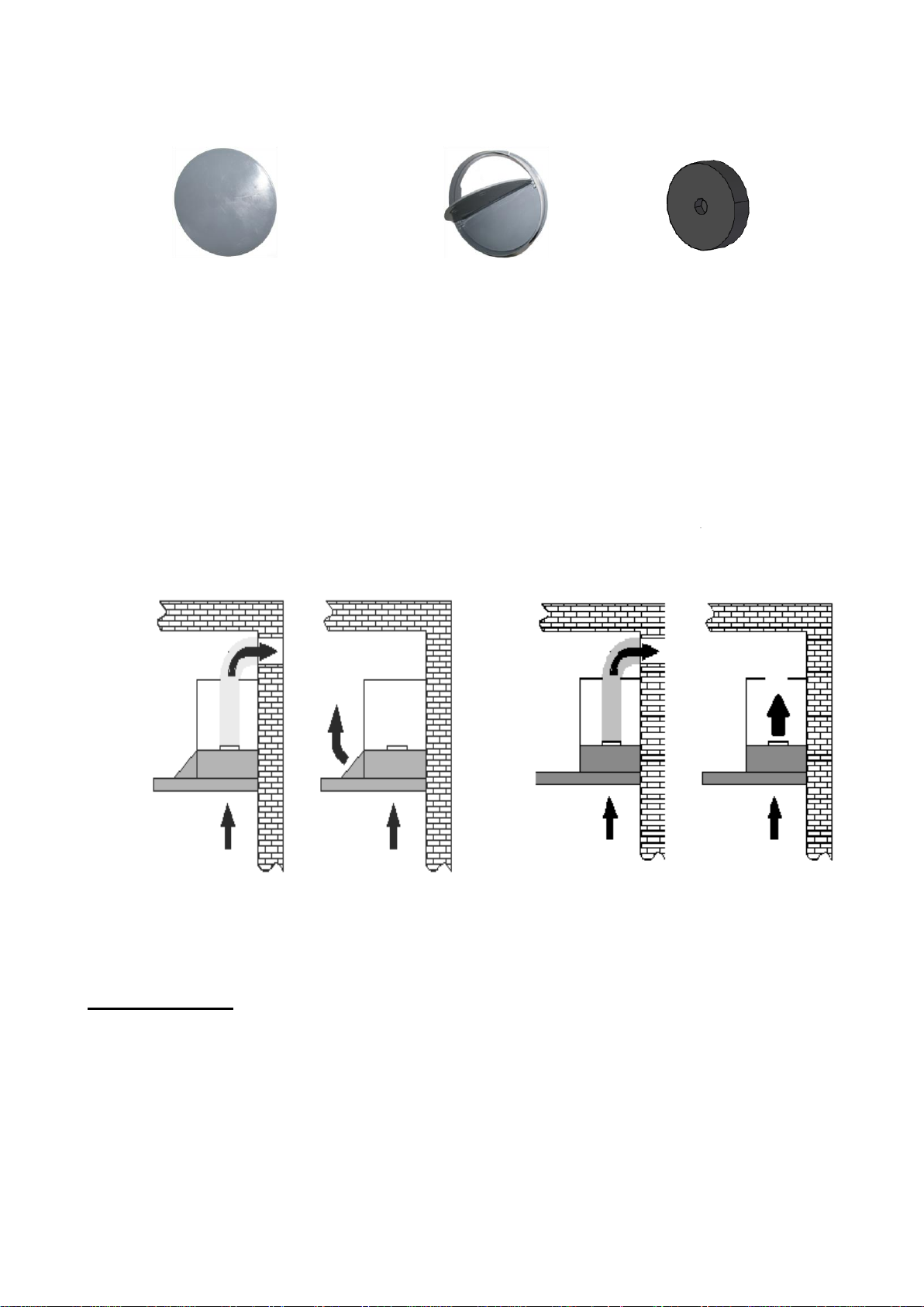
During assembly work, the applicable provisions regarding air exhaust must be
observed.
ATTENTION:
If the manual of the gas or electric cooker orders a different, larger distance from
the hood than 65 cm, then it should be used.
Fig. 16
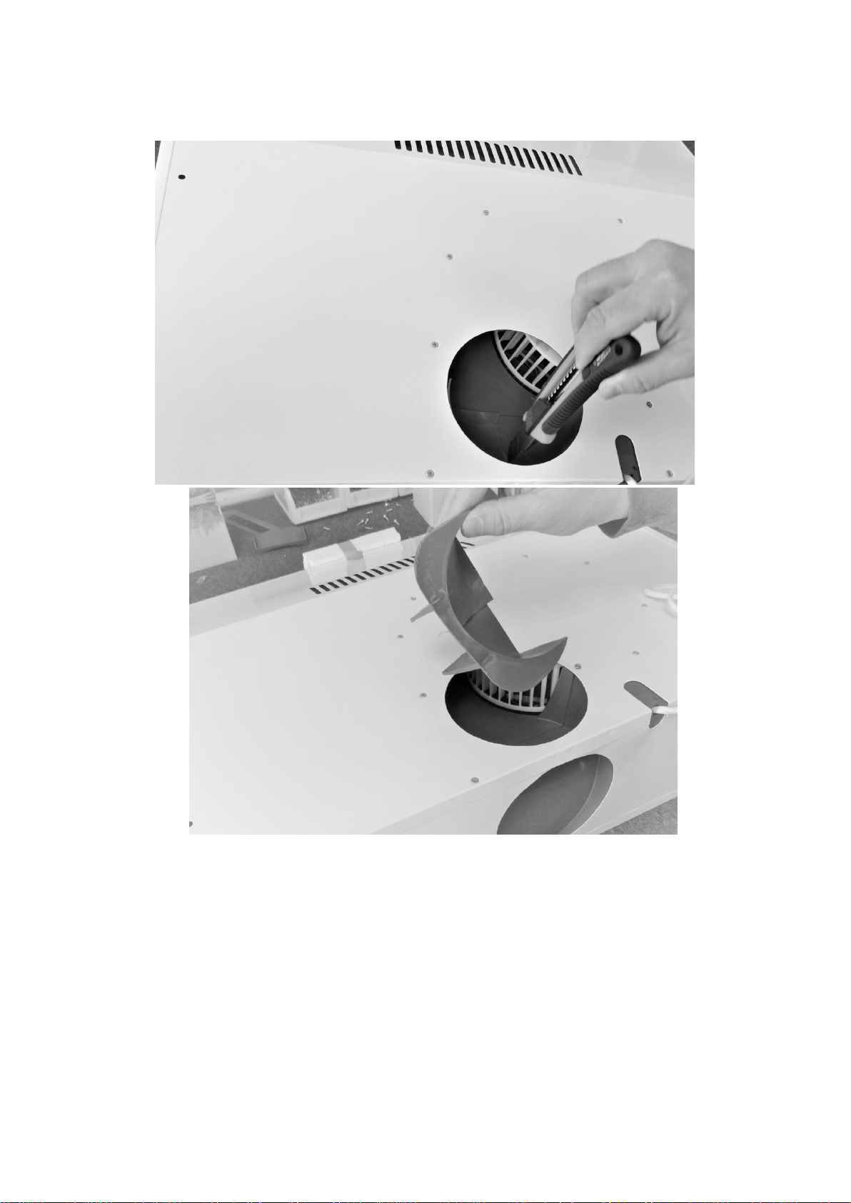
3.1 INSTALLATION OF EXHAUST HOUSING LIGHT, P3050/60
•Disassemble the aluminum grease filter (Fig. 17),
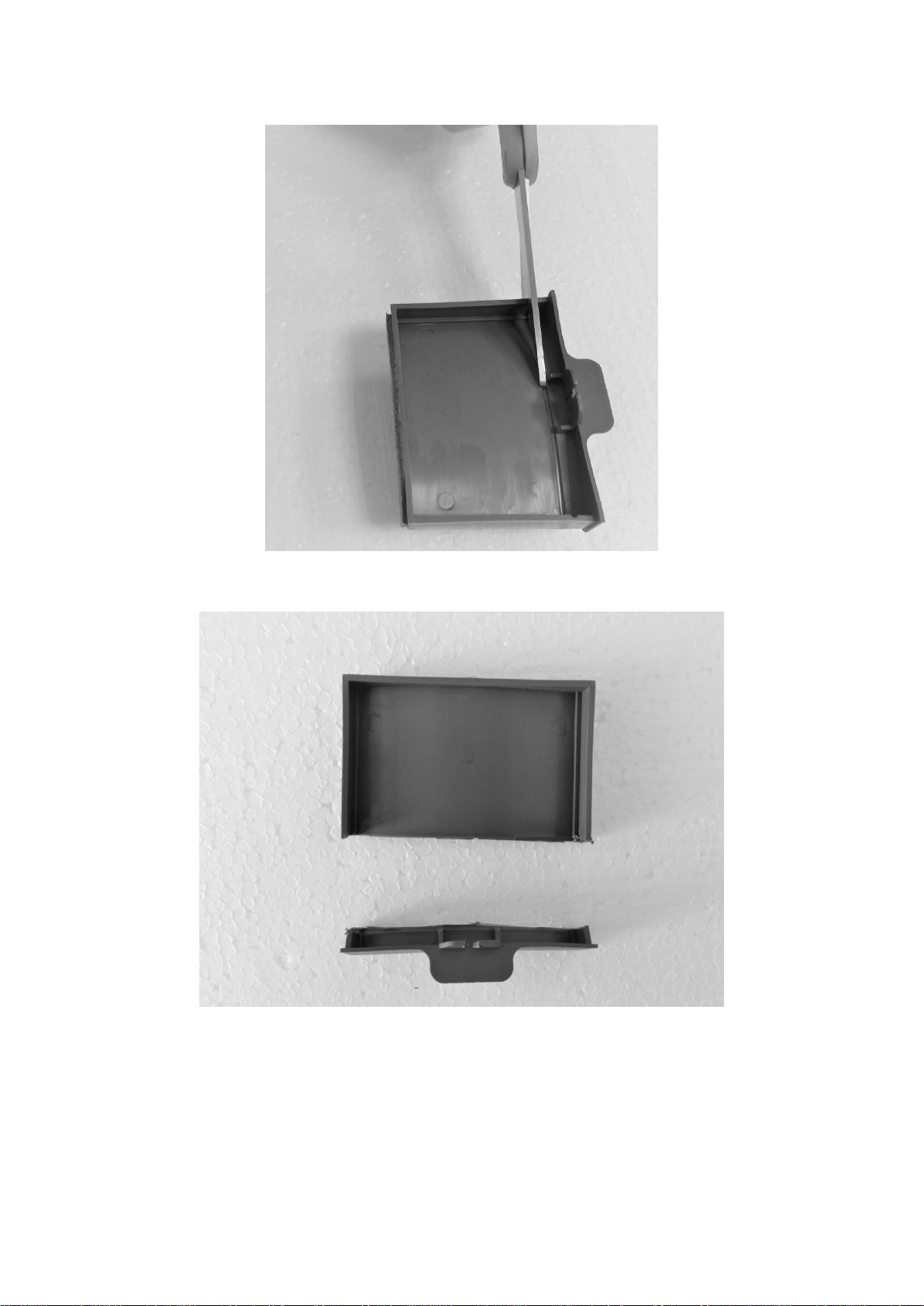
•Prepare the cabinet with the appropriate dimensions depending on the type of eaves
LIGHT GLASS / LIGHT / LIGHT ECO / LIGHT ECO R/ LIGHT ECO GLASS /
LIGHT PLUS (Fig. 18), P3050 (Fig. 22), P3060 (Fig. 23),
•Put the hood into the previously prepared cabinet (Fig. 19),

11
•Screw the cover to the inside shelf using four 3x16 screws (Fig. 20) that are
attached to the kit, or drill two holes in the wall to attach the cover to the wall
using the included 10x50 dowels,
•If the cap will be used as an exhaust cap (Fig. 4a), install a non-return valve (Fig.
5) into the outlet of the turbine and install a steam return pipe (Fig. 21) on it.
•Install the aluminum grease filter (Fig. 17).
Fig. 17
Fig. 18

12
Fig. 19

13
Fig. 20
Fig. 21
P3050

14
Fig. 22
P3060
Fig. 23

15
4. OPERATION
4.1 CONTROLPANEL
Hoods of type WK-7 are equipped with mechanical or electronic control without display.
A B C D E F
Fig. 24
A B
Fig. 25
A B C D E
Fig. 26
Control (Fig. 24):
A - turning the light on and off
B - turbine speed I
C - turbine speed II
D - turbine speed III
E - turbine shut-down
F - turbine lamp
Control (Fig. 25):
A - turning the light on and off
B –turbine speed I, II and III
Control (Fig. 26):

16
A - turbine lamp
B - turning the light on and off
C - turbine speed I
D - turbine speed II
E - turbine speed III
In Light, Light Plus and Light Eco hoods, work is possible after the drawer has been
closed. The switch is equipped with a function of automatic shut-down of the turbine and
lighting after 15 minutes.
TIMER
To enable this feature:
Press the turbine operation select button until the indicator light flashes above the button.
The timer is on.
Remote
The hood (LIGHT PLUS) can be controlled using the remote control
Fig. 27
Button definition (fig. 27)
1 - TIMER
Triggers a temporary hood switch,
2 - MINUS
Adjusts the speed of the turbine to turn off,
3 - PLUS
Turns the turbine on and adjusts the speed of the turbine.
4 - LIGHTING

17
Turning on and off the lighting,
5. CLEANING AND CARE
Regular maintenance and cleaning will ensure high performance and reliability of the hood
while simultaneously prolonging its lifecycle.
Pay particular attention to replacing grease filters and activated carbon filters in accordance
with the manufacturer’s recommendations.
5.1 GREASE FILTER
The hoods have aluminium filters (Fig. 29) which should be cleaned depending on the
intensity of cooking at least once a month. In order to clean the aluminium filter, it must
be removed from the body and rinsed with warm water with the addition of a grease
dissolving agent or in a dishwasher, after being placed in a vertical position. When
cleaning the aluminium filter, take care not to damage the mesh. After washing and
drying, insert the filter in its place in the hood.
When the aluminium filter works in the drain mode and is not cleaned regularly, it wears
out faster, and the efficiency of the hood diminishes.
Fig. 28
5.2 CARBON FILTER
In operating mode, as an absorber, carbon filters absorb odors associated with cooking. The
hood has been designed so that two carbon filters T300 can be mounted on both sides of the
turbine (LIGHT GLASS / LIGHT ECO GLASS / LIGHT ECO / LIGHT / LIGHT PLUS /
LIGHT ECO R/ LIGHT ECO) or one P30 (P3050/60). Carbon filters are not suitable for
regeneration and should be replaced at least once every 3 months or more often in the case
of intensive use of the hood.
Carbon filter replacement T300, P30
1. Disconnect the hood from the electrical outlet.

18
2. Remove the grease filter
3. Remove the carbon filter, which is located inside the exhaust hood on the motor
housing (P30, Fig. 29), or on both sides of it (T300, Fig. 30) rotating it counter-
clockwise.
4. Then, repeating all the steps from step 3 in the reverse order, install a new filter on the
turbine engine housing and turn it well to protect it against slipping.
Fig. 29 Fig. 30
5.3 LIGHTING
LIGHT hoods can be equipped with LED lighting with GU10 fixing, or
filament lamps depending on the model (see - product card).
Fig. 31 Fig. 32
Replacing light bulbs (Fig. 31)
1. To replace an ordinary light bulb
2. Open the grease filter screens
3. On the inside of the hood, unscrew the light bulb
4. Screw in a new light bulb (no more than 4 W, see the shield)

19
5. Insert grease filters
6. Connect the hood to the electrical outlet.
To replace the LED bulb (Fig. 32) proceed as follows:
1. Disconnect the hood from the electrical outlet
2. Press the bulb and turn it about 45° counter-clockwise
4. Remove the old bulb
5. Insert a new light bulb (2 W max, see the shield), in the reverse order
6. Connect the hood to the electrical outlet.
5.4 CLEANING
Unplug the power cord before cleaning. For external cleaning, use a damp cloth and a
non-toxic detergent.
Note:
1. If cleaning and maintenance are not carried out in accordance with the
instructions, there is a risk of fire.
2. If you use a gas stove, do not leave open fire.
3. The device is not intended for use by persons (including children) with
physical, sensory or mental disabilities.
4. The device is not intended to entertain children.
5. The air from the hood must not be vented to the chimney used to remove
exhaust gases from gas combustion devices or other fuels.
6. If the permanently built-in power cord is damaged, it must be replaced
by a special cord or block that can be purchased from the manufacturer
or from a specialized repair centre.
7. The manufacturer shall not be liable for any non-compliance with the
rules of installation and operation, as well as improper handling of the
hood.
CAUTION:
External parts may become very hot during use.
Table of contents
Other akpo Ventilation Hood manuals
Popular Ventilation Hood manuals by other brands

Küppersbusch
Küppersbusch IKD 9600 Instruction booklet

Midea
Midea MHC60GSS instructions

Zephyr
Zephyr Tempest II AK7500CS Use, care and installation guide

Bosch
Bosch DWK096750 Operating and installation instructions

Frigidaire
Frigidaire PL36WC50EC Professional series use & care

Schweigen
Schweigen UM-12UMS installation guide