AL-KO HWA 800 MC User manual

HAUSWASSERAUTOMAT
ELECTRONIC DOMESTIC WATER SYSTEM
GROUPE DE SURPRESSION ÉLECTRONIQUE
AUTOCLAVE ELETTRONICA
GRUPO DE PRESSÃO ELECTRÓNICO
AUTOCLAVE ELECTRÓNICO
ELEKTRONISCHE WATERRESERVOIR
ÁÕÔÏÌÁÔÇ AÍÔËÉÁ ÍÅÑÏÕ
ELEKTRONIK HIDROFOR
ÍÀÑÎÑ-ÀÂÒÎÌÀÒ
POMPA Z HYDROSTATEM
DOMÁCA VODÁREÒ S HYDROKONTROLOU
DOMÁCÍ VODÁRNA S HYDROKONTROLOU
HÁZI VÍZAUTOMATA
PUMPEAUTOMAT
KOTITALOUKSIEN VESIPUMPUT
PUMPAUTOMAT
BEDIENUNGSANLEITUNG
OPERATING INSTRUCTIONS
MODE D’EMPLOI
ISTRUZIONI D’USO
MANUAL DO USUÁRIO
INSTRUCCIONES PARA EL USO
GEBRUIKSAANWIJZING
OÄÇÃÉÅÓ XÑÇÓÇÓ
KULLANIS BILGILERI
ÈÍÑÒÐÓÊÖÈÿ ÏÎ ÝÊÑÏËÓÀÒÀÖÈÈ
INSTRUKCJA U¿YTKOWANIA
NÁVOD NA POUITIE
NÁVOD NA POUITÍ
HASZNÁLATI UTASÍTÁS
BRUGSANVISNING
KÄYTTÖOHJE
BRUKSANVISNING
HWA 800/MC
GPI 900/3
Compakt
GPI 1100/4
Compakt
GPI 5100/3
ELECTRONIC
P1720440

2
Inhaltsverzeichnis Seite
Bildteil 3
Bedienungsanleitung 4-9
D
Table of Contents Page
Illustrations 3
Operating Instructions 10-15
GB
Index Page
Figures 3
Moded’emploi 16-21
F
Ðåñéå÷üìåíá Óåëßäá
Ó÷Ýäéá 3
Ïäçãßåò÷ñÞóçò 46-51
GR
Indice Pagina
Figure 3
Istruzioni d‘uso 22-27
I
Índice Página
Figuras 3
Manual do usuário 28-33
P
Índice Página
Figuras 3
Instrucciones para el uso 34-39
E
Inhoud Pagina
Afbeeldingen 3
Gebruiksaanwijzing 40-45
NL
Içindekiler Sayfa
Sekiller 3
Kullanisbilgileri 52-57
TR
Ñîäåðæàíèå Ñòðàíèöà
Ðèñóíêè 3
Èíñòðóêöèÿ ïî Ýêñïëóàòàöèè 58-63
Spis treci Strona
Rysunki 3
Instrukcja u¿ytkowania 64-69
PL
Obsah Strana
Obrázky 3
Návod na pouitie 70-75
SK
Tartalomjegyzék Oldal
Ábrák 3
Használati utas tás 82-87
H
RUS
Obsah Strana
Obrázky 3
Návod na pouit 76-81
CZ
Indholdsfortegnelse Side
Billeddel 3
Brugsanvisning 88-93
DK
Sisältö Sivu
Kuvaosa 3
Käyttöohje 94-99
SF
Innehållsförteckning Sida
Bilddel 3
Bruksanvisning 100-105
S

3
AB
CD

4
EINLEITUNG
Lesen Sie vor der Inbetriebnah e Ihres Hauswas-
serauto aten diese Bedienungsanleitung sorgfäl-
tig durch. Dies ist die Voraussetzung für sicheres
Arbeiten und störungsfreie Handhabung.
Bewahren Sie die Bedienungsanleitung stets ver-
fügbar auf und geben Sie diese auch an Nachbe-
nutzer weiter.
Nachfolgend sind die in dieser Bedienungsanlei-
tung verwendeten Sy bole erläutert:
VORSICHT
steht bei Arbeits- oder Betriebsverfahren, die ge-
nau einzuhalten sind, u eine Gefährdung von
Personen auszuschließen.
ACHTUNG
enthält Infor ationen, die beachtet werden üs-
sen, u Schäden a Gerät zu verhindern.
HINWEIS
steht für technische Erfordernisse, die besonders
beachtet werden üssen.
SICHERHEITSHINWEISE
Das Gerät darf nur an einer elektrischen Ein-
richtung ge äß DIN/VDE 0100, Teil 737, 738
und 702 (Schwi bäder) betrieben werden. Zur
Absicherung uss ein Leitungs-Schutzschalter
10 A sowie ein Fehlerstro schutzschalter it ei-
ne Nennfehlerstro von 10/30 A installiert sein.
Die Angaben über Netzspannung und Stro art a
Typenschild üssen it den Daten Ihres
Elektronetzes übereinsti en.
Verwenden Sie nur Verlängerungskabel
3 x 1,5 2 der Qualität H07RN-F nach
DIN 57282/57245 it spritzwassergeschütz-
ter Steckvorrichtung. Kabeltro eln üssen voll-
ständig abgerollt sein.
Das Gerät darf nicht betrieben werden von
– Personen, die die Bedienungsanleitung
nicht gelesen und verstanden haben
– Kindern und Jugendlichen unter 16 Jahren.
Die Pu pe darf nur besti ungsge äß
verwendet werden. Stellen Sie vor Ge-
brauch sicher, dass
– das Gerät, das Anschlusskabel und der Netz-
stecker nicht beschädigt sind.
Beschädigte Geräte dürfen nicht betrieben
werden. Reparaturen dürfen nur durch un-
sere Kundendienst-Werkstätten durchgeführt
werden.
Den Hauswasserauto at nie a Anschlus-
skabel hochheben, transportieren oder be-
festigen. Benutzen Sie das Anschlusskabel nicht,
u den Netzstecker aus der Steckdose zu ziehen.
Ziehen Sie vor Wartungs-, Pflege- und Re-
paraturarbeiten oder bei Störungen stets den
Netzstecker. Schützen Sie den Netzstecker vor
Feuchtigkeit.
Jegliche eigen ächtigen Veränderungen
oder U bauten a Gerät sind verboten.
VERWENDUNGSZWECK
Bestimmungsgemäße Verwendung
Der Hauswasserauto at ist für die private Nut-
zung in Haus und Garten besti t. Sie darf nur i
Rah en der Einsatzgrenzen ge äß den techni-
schen Daten betrieben werden. Das Gerät ist aus-
schließlich für folgende Anwendungen geeignet:
– Garten- und Grundstücksbewässerung
– Wasserversorgung i Haus
– Druckerhöhung in der häuslichen Wasserver-
sorgung. Beachten Sie die örtlichen Vorschrif-
ten der Wasserversorgung. Fragen Sie Ihren
Sanitärfach ann.
Das Gerät ist ausschließlich zu Fördern von fol-
genden Flüssigkeiten geeignet:
– Klarwasser
– Regenwasser
– Schwi badwasser.
D

5
GERÄTEAUFSTELLUNG, INBETRIEBNAHME
• Stellen Sie die Pu pe auf einen ebenen, über-
flutungssicheren, festen und waagerechten
Standort.
• Stellen Sie sicher, dass Ihr Hauswasserauto-
at vor Regen und direkte Wasserstrahl ge-
schützt ist.
Achten Sie bei Montieren der Saug- und
Druckschlauchleitungen, dass kein echa-
nischer Druck oder Zug auf das Gerät ausgeübt
wird. Wir e pfehlen den Einbau von flexiblen Lei-
tungen a Pu peneingang und a
Pu penausgang. Fragen Sie auch Ihren Fach-
händler.
I täglichen Betrieb (Automatikbetrieb)
üssen Sie durch geeignete Maßnah en
ausschließen, dass bei Störungen a Gerät Fol-
geschäden durch die Überflutung von Räu en
entstehen.
Saugleitung montieren
Wählen Sie die Länge der Saugleitung so aus,
dass die Pu pe nicht trockenlaufen kann. Der
Saugschlauch uss sich i er 30 c unterhalb
der Wasseroberfläche befinden.
• Montieren Sie die Saugleitung. Achten Sie da-
bei auf dichten Anschluss, ohne das Gewinde
zu beschädigen.
Bei einer Ansaughöhe über 4 sollte ein
Saugschlauch it eine Durch esser von
indestens 1“ ontiert werden. Wir e pfehlen das
Verwenden einer AL-KO-Sauggarnitur (14) it
Saugschlauch, Saugkorb und Fußventil (Rück-
flussstop). Fragen Sie dazu Ihren Fachhändler.
Bei geringfügig sandhaltige Wasser uss
zwischen Saugleitung und Pu peneingang
ein AL-KO-Vorfilter (13) eingebaut werden. Fragen
Sie dazu Ihren Fachhändler.
• Verlegen Sie die Saugleitung stetig steigend.
Bei Verlegen über Pu penhöhe bilden sich
Luftblasen in der Leitung.
Druckleitung montieren
• Montieren Sie die Druckleitung. Achten Sie da-
bei auf dichten Anschluss, ohne das Gewinde
zu beschädigen.
Das Gerät funktioniert nicht ordnungsge äß,
wenn die Entnah estelle 15 höher als das
Gerät liegt.
Bestimmungswidrige Verwendung
Die Pu pe darf nicht i Dauerbetrieb eingesetzt
werden. Sie ist nicht geeignet zur Förderung von
– Salzwasser
– Lebens itteln
– Sch utzwasser it Textil- oder Papieranteilen
– aggressiven Medien, Che ikalien
– ätzenden, brennbaren, explosiven oder gasen-
den Flüssigkeiten
– Flüssigkeiten, die wär er als 35 °C sind
– sandhaltige Wasser und sch irgelnden Stof-
fen.
GERÄTEBESCHREIBUNG
Hauswasserautomat und Zubehör
(Bild A, B und C)
1 Pu peneingang/Saugleitungsanschluss
2 Rückschlagventil
3 Einfüllstutzen
4 Pu penausgang/Druckleitungsanschluss
5 Elektronik-Funktionsanzeige
6 Taste "Reset"
7 Kontrollleuchte "Power" (LED), Netzspannung
8 Kontrollleuchte "Pu p on" (LED), Pu pe an
9 Kontrollleuchte "Alar " (LED)
10 Kontrollleuchten "Flow" (LED), Förder enge
11 Netzkabel it Schukostecker
12 Ablassschraube
13 Vorfilter (Zubehör)
14 AL-KO-Sauggarnitur (Zubehör)
Lieferumfang
Der Hauswasserauto at ist it integrierte
Druckschalter, Trockenlaufschutz, Rückschlag-
ventil und eine Netzkabel it Schukostecker aus-
gestattet.
Funktion
Der Hauswasserauto at arbeitet auto atisch. Die
Pu pe schaltet sich druckabhängig ein und aus
(siehe technische Daten).
Wird eine Entnah estelle geöffnet saugt die Pu -
pe Wasser über die Saugleitung (1) an und fördert
es durch den Druckleitungsanschluss (4) zur Ent-
nah estelle.
Die Pu pe schaltet ca. 15 Sekunden nach Schlie-
ßen der Entnah estelle auto atisch ab.
Thermoschutz
Die Pu pe ist it eine Ther oschalter ausge-
stattet, der die Pu pe bei Überhitzung abschaltet
(siehe Störungen).
D

6
Pumpe befüllen
Die Pu pe uss vor jeder Geräteaufstel-
lung/Inbetriebnah e bis zu Überlauf it
Wasser gefüllt werden, da it sie sofort ansaugen
kann. Trockenlauf zerstört die Pu pe.
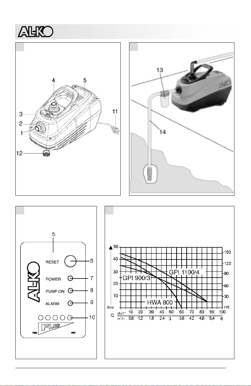
• Entfernen Sie die Verschlussschraube vo Ein-
füllstutzen (3).
• Füllen Sie über den Einfüllstutzen Wasser ein,
bis dieser überläuft.
Der Saugschlauch kann nicht über den Ein-
füllstutzen gefüllt werden, da zur Saugseite
hin ein Rückschlagventil (2) eingebaut ist.
• Schrauben Sie die Verschlussschraube in den
Einfüllstutzen ein.
Erstinbetriebnahme des Gerätes
• Öffnen Sie den in der Druckleitung vorhande-
nen Verschluss (Ventil, Spritzdüse, Wasser-
hahn), da it die Luft aus der Druckleitung ent-
weichen kann.
• Stecken Sie den Netzstecker des Anschlusska-
bels in die Steckdose. Die Pu pe beginnt zu
arbeiten.
Bei Starten arbeitet die Pu pe zunächst 2
Minuten, dann stoppt sie für wenige Sekun-
den, u Luftblasen entweichen zu lassen und star-
tet erneut.
Ko t nach drei Versuchen i er noch kein
Wasser, üssen alle Anschlüsse des Gerätes so-
wie die Füllung der Pu pe überprüft werden.
• Schließen Sie den Verschluss in der Drucklei-
tung, nachde Wasser ohne Lufteinschlüsse
aus der Leitung geflossen ist. Die Pu pe schal-
tet nach ca. 15 Sekunden auto atisch ab. Der
Hauswasserauto at ist betriebsbereit.
BEDIENUNG DES GERÄTES
• Neh en Sie das Gerät wie beschrieben in Be-
trieb (Erstinbetriebnah e des Gerätes).
Der Hauswasserauto at ist elektronisch geregelt
und arbeitet nach Erstinbetriebnah e vollauto a-
tisch.
Trockenlaufschutz der Pumpe
Das Gerät schaltet bei Wasser angel nach ca. 45
Sekunden auto atisch ab. Dies wird auf der
Elektronik-Funktionsanzeige durch Blinken
der roten Kontrollleuchte "Alar " (9) angezeigt.
Schutz bei Leckagen in der Druckleitung
Bei Leckagen (auch bei kleinen Undichtheiten) in
der Druckleitung schaltet die Pu pe durch den sich
ständig wiederholenden Druckabfall dauernd ein
und aus.
Nach 40 Ein- Ausschaltvorgängen innerhalb kür-
zester Zeit schaltet die Pu pe entgültig aus. Die
Leuchtdioden der Durchflussanzeige leuchten
nacheinender auf (Lauflicht).
Zu Neustart der Pu pe ziehen sie den Netzstecker
und stecken e eut ein.
Automatischer Neustart
Das Gerät versucht drei al einen automatischen
Neustart:
– nach einer Stunde
– nach 5 Stunden
– nach 20 Stunden.
Scheitern alle drei Versuche, bleibt das Gerät aus-
geschaltet. Dies wird auf der Elektronik-Funktions-
anzeige durch Leuchten der roten Kontrollleuchte
"Alar " (9) angezeigt. Zu erneuten Starten des
Gerätes gehen Sie wie folgt vor:
• Ziehen Sie den Netzstecker.
• Überprüfen Sie die saugseitige Wasserversor-
gung.
• Neh en Sie das Gerät wie beschrieben in Be-
trieb (Erstinbetriebnah e des Gerätes).
Zwischen den auto atischen Neustartversu-
chen können Sie das Gerät durch Drücken
der Taste "Reset" (6) anuell starten.
Manueller Neustart
• Überprüfen Sie die Saugseite des Gerätes und
das Wasserniveau.
• Starten Sie die Pu pe durch Drücken der Taste
"Reset" (6).
Pumpe ausschalten
•
Ziehen Sie den Netzstecker aus der Steckdose.
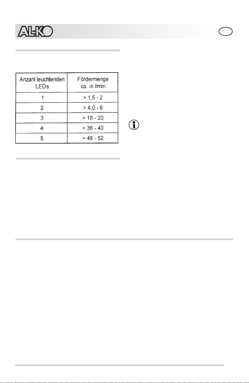
BETRIEBSZUSTANDSANZEIGEN
Die Betriebszustände werden it Hilfe von Kon-
trollleuchten (Leuchtdioden, LED) angezeigt.
Kontrollleuchte "Power" (Grün)
Zeigt an ob das Gerät a Netz angeschlossen ist.
Kontrollleuchte "Pump on" (Gelb)
Zeigt an, dass die Pu pe in Betrieb ist.
Kontrollleuchte "Alarm" (Rot), blinkt
Der Trockenlaufschutz hat aufgrund von Was-
ser angel auf der Saugseite ausgelöst.
Kontrollleuchte "Alarm" (Rot) leuchtet
Das Gerät hat nach drei auto atischen Neustart-
versuchen abgeschaltet.
D

7
WARTUNG UND PFLEGE
Vor Beginn jeder Wartungsarbeit ist das Gerät vo
Netz zu trennen und gegen Wiedereinschalten zu
sichern!
Reinigungsarbeiten
– Nach Förderung von chlorhaltige Schwi -
badwasser oder Flüssigkeiten, die Rückstän-
de hinterlassen, uss die Pu pe it klare
Wasser durchgespült werden.
ANZEIGE DER FÖRDERMENGE
Die o entane Förder enge in l/ in kann an den
Kontrollleuchten "Flow" (10) der Elektronik-Funk-
tionsanzeige abgelesen werden.
Verstopfungen beseitigen
Verstopfungen der Pu pe wie folgt beseitigen:
• Entfernen Sie den Saugschlauch a Pu pen-
eingang.
• Schrauben Sie den Saugleitungsanschluss (1)
it de Rückschlagventil (2) heraus.
• Schließen Sie den Druckschlauch vo Druck-
leitungsanschluss (4) an die Wasserleitung an
und lassen Sie Wasser durch das Pu penge-
häuse laufen, bis die Verstopfung beseitigt ist.
• Vor Wiederinbetriebnah e können Sie durch
kurzes Einschalten prüfen, ob die Pu pe frei
dreht.
Achten Sie bei Einbau des Rückschlagven-
tilsauf richtigen Sitz.
• Schrauben Sie den Saugleitungsanschluss (1)
it de Rückschlagventil (2) ein.
• Neh en Sie die Pu pe wie beschrieben wie-
der in Betrieb.
Frostschutz
Bei Frostgefahr uss der Hauswasserauto at
vollständig entleert werden (Leitungen und Pu -
pe).
• Entleeren Sie die Saug- und Druckleitung.
• Schrauben Sie die Ablassschraube (12) heraus
und lassen Sie das Wasser aus der Pu pe
auslaufen.
• Ablassschraube wieder einschrauben und den
Hauswasserauto aten frostfrei lagern.
TECHNISCHE DATEN
Typ HWA 800 GPI 900/3 GPI 1100/4
Artikelnu er 110 964 110 938 110 937
Nennleistung 800 W 900 W 1100 W
Netzspannung 230-240 V 230-240 V 230-240 V
Frequenz 50 Hz 50 Hz 50 Hz
Schutzklasse IPX4 IPX4 IPX4
Schalle ission < 58 dB(A) < 58 dB(A)
Ansaughöhe ax. 9 8 8
Förderhöhe ax. 42 /4,2 bar 35 /3,5 bar 45 /4,5 bar
Förder enge ax. 3600 l/h 5100 l/h 5100 l/h
Te peratur Förder-
ediu ax. 35 °C 35 °C 35 °C
Pu pen-Laufwerk 1-stufig 3-stufig 4-stufig
Saug-Druck-Leitung Ø 1“ 1“ 1“
Gewicht 8,1 kg 11 kg 11 kg
D
GPI 5100/3
112 142
900 W
230-240 V
50 Hz
IPX4
< 58 dB(A)
8
38 /3.8 bar
5100 l/h
35 °C
3 stufig
1“
11 kg
Pu penkennlinien siehe Bild D.

8
D
STÖRUNG
Vor allen Arbeiten zur Störungsbeseitigung den Netzstecker ziehen.
gnurötSnegieznA-DELehcasrUgnugitieseB
epuPeiD
thcintfuäl
"rewoP"DEL
thcintethcuel
gnunnapszteNenieK
nednahrov
kinortkelErednirelheF
nov.fgg,nefürpgnugrosrevortS
nessalnefürptfarkhcafortkelE
tsneidnednuKOK-LA
negithcirhcaneb
"rewoP"DEL
,tethcuel
"nopuP"DEL
,thcintethcuel
"ralA"DEL
thcintethcuel
tsignutielkcurDeiD
tfpotsrev
slarehöhtsielletsehantnE
51
nefürprebügnutielkcurD
nregnirrevehöhehantnE
"rewoP"DEL
,tethcuel
"nopuP"DEL
,tethcuel
NAtsi"ralA"DEL
kinortkelErednirelheFtsneidnednuKOK-LA
negithcirhcaneb
"rewoP"DEL
,tethcuel
"nopuP"DEL
,thcintethcuel
tknilb"ralA"DEL
02netztelreddnerhäW
nalegnaressaWnednutS
etiesguaSred
treikcolbdarfuaL
tsölegsuatahztuhcsorehT
dnuessülhcsnAegitiesguaS
nefürprebüdnatsressaW
etsaT,epuPeideiSneginieR
nekcürdteseR
"rewoP"DEL
,tethcuel
"nopuP"DEL
,thcintethcuel
"ralA"DEL
tethcuel
nednutS02slarhetieS
rednalegnaressaW
etiesguaS
treikcolbdarfuaL
tsölegsuatahztuhcsorehT
dnuessülhcsnAegitiesguaS
nefürprebüdnatsressaW
täreGsad,neheizrekcetszteN
nehenbeirteBnituenre
etsaT,epuPeideiSneginieR
nekcürdteseR
-redröF
uzegne
gnireg
gnufpotsreVegitiesguaS
ßorguzehöhguasnA
uzressehcrudhcualhcS
nielk
ßorguzehöhredröF
neginierhcierebguasnA
nregnirrevehöhguasnA
hcualhcskcurDnereßörG
nednewrev
nregnirrevehöhredröF
epuP
natfuäl
dnu
tetlahcs
baredeiw
nedninegakceL
negnutielkcurD
reduaevinressaWsaD
rhestinetiesguaS
ballenhcs
nefürprebünegnutielkcurD
gnugrosrevressaWednehciersua
hcualhcsguaSned,nelletsrehcis
nehcuatnierefeit
Störung
Die Pu pe
läuft nicht
Stro versorgung prüfen, ggf. von
Elektrofachkraft prüfen lassen
Die Druckleitung ist
verstopft
Entnah estelle ist höher
als 15
Druckleitung überprüfen
Entnah ehöhe verringern
Während der letzten 20
Stunden Wasser angel
an der Saugseite
Laufrad blockiert
Ther oschutz hat ausgelöst
Saugseitige Anschlüsse und
Wasserstand überprüfen
Reinigen Sie die Pu pe, Taste
Reset drücken
Laufrad blockiert
Ther oschutz hat ausgelöst
Saugseitige Anschlüsse und
Wasserstand überprüfen
Netzstecker ziehen, das Gerät
erneut in Betrieb neh en
Reinigen Sie die Pu pe, Taste
Reset drücken
Pu pe
läuft an und
schaltet
wieder ab
Druckleitungen überprüfen
LED "Alar "
blinkt und LED
Durchfluss-
anzeige läuft
zyklisch durch
Druckleitungen abdichten, Pu pe
aus und wieder einstecken
Leckage in der
Druckleitung
Förder-
enge zu
gering
Saugseitige Verstopfung
Ansaughöhe zu groß
Schlauchdurch esser zu
klein
Förderhöhe zu groß
Ansaugbereich reinigen
Ansaughöhe verringern
Größeren Druckschlauch
verwenden
Förderhöhe verringern
Leckagen in den
Druckleitungen

9
GARANTIE
Die Garantie auf dieses Gerät beträgt
24 Monate ab Kaufdatu .
Die Garantie erstreckt sich ausschließlich auf alle
Mängel des Gerätes, die nachweislich auf Mate-
rial- oder Fabrikationsfehler zurückzuführen sind.
Garantieansprüche gelten nur
– für Geräte, die sachge äß behandelt wurden
– wenn die Bedienungsanleitung beachtet wurde
– für Originalteile
– bei ausgefüllter Garantiekarte
– bei Vorlage der Rechnung.
Die Garantie erlischt
– bei Reparaturversuchen a Gerät
– bei jeglicher Änderung a Gerät
– bei nicht besti ungsge äßer Verwendung.
Eine weitere Haftung wird nicht überno en.
Bitte schneiden Sie i Rekla ationsfall die Ga-
rantiekarte aus und senden Sie die Karte zusa -
en it de Hauswasserwerk ein.
GARANTIEKARTE
Pu pe
Typ
Artikelnu er
Kaufdatu
Beanstandung/Fehler
Unterschrift
EG-KONFORMITÄTSERKLÄRUNG
Ge äß der EG-Maschinenrichtlinie 89/392/EWG
erklären wir hier it, dass das nachfolgend be-
zeichnete Produkt aufgrund seiner Konzipierung
und Bauart sowie in der von uns in Verkehr ge-
brachten Ausführung den einschlägigen grund-
legenden Sicherheits- und Gesundheitsanforde-
rungen der EG-Richtlinie entspricht. Bei einer nicht
it uns abgesti ten Änderung des Produktes
verliert diese Erklärung ihre Gültigkeit.
Produktbeschreibung
Pu pe, elektrisch
Hersteller
AL-KO Geräte G bH
Ichenhauser Str. 14
D-89359 Kötz
Typ
HWA 800 MC
GPI 900/3 Co pakt
GPI 1100/4 Co pakt
GPI 5100/3 electronic
Angewendete einschlägige EG-Richtlinien
EG-Maschinenrichtlinie (89/392/EWG)
Elektro agnetische Verträglichkeit (89/336/EWG)
EG-Niederspannungsrichtlinie (73/23/EWG)
Angewendete harmonisierte Normen
EN 60335-1:1994
EN 60335-2-41:1996
EN 55014-1:1993
EN 55014-2:1997
EN 61000-3-2:1995
EN 61000-3-3:1995
Kötz, den 01. 01. 2001
(Antonio De Filippo, Entwicklungsleitung)
SICHERHEITS- UND PRÜFZEICHEN
D

10
INTRODUCTION
Please read the operating instructions carefully
before you use the do estic water pu p to pre-
vent accidents and ensure the trouble-free ope-
ration of the device.
Make sure you keep the instructions at hand for
quick reference. If you resell your pu p or give it
to another user, please include these instructions
in the sale or the gift.
The following sy bols are used in the instructions:
DANGER
This sy bol draws your attention to work
processes or operating procedures that have to
be carefully observed in order to prevent serious
injury to the user or another person.
CAUTION
This sy bol draws your attention to infor ation
you need to ensure that your syste is not da a-
ged due to i proper or careless use.
PLEASE NOTE
The infor ation sy bol draws your attention to
essential technical require ents.
FOR YOUR SAFETY
The do estic water pu p ay only be con-
nected to an electrical device which is co -
pliant with DIN/VDE 0100, Parts 737, 738 and 702
(swi ing pools). Make sure that fuse protection
in the for of a 10 A auto atic cut-out and a fault
current guard circuit with a no inal fault current
of 10/30 A is installed.
The supply voltage and current specified
on the type plate ust be identical with the
voltage and current of your electrical syste .
If you need to connect your do estic water
pu p to an extension cord, ake sure that
the cable is 3 x 1.5 2, that it corresponds to
type H07RN-F and is co pliant with DIN 57282/
57245. The connector ust be splash-proof. Cable
dru s ust be co pletely unwound.
Please ake sure that the device is not
operated by anyone
– who has not read or does not fully understand
the operating instructions or
– is under the age of 16.
The do estic water pu p ay not be used
for any other than its designated use. Before
putting the device into operation, ake sure that
– the pu p, the electric cable and the plug are
not worn or da aged.
Do not operate the device if it is da aged.
Necessary repairs ust be carried out in a
qualified AL-KO service centre.
Never use the electric cable to lift, carry or
attach the device to another object. Do not
pull on the cable when unplugging the pu p.
Make sure that the pu p is unplugged
before beginning any aintenance, repair
or cleaning work. In the event of a alfunction,
i ediately unplug the pu pr. Make sure that the
plug does not get wet.
Do not atte pt to ake any changes or
odifications to the device by yourself. You
ay endanger your life or invalidate the warran-
ty.
USE
Designated use
The do estic water pu p is designed for ho e
use in your house or garden. Please observe the
technical data given in the instructions before put-
ting the device into operation.
Your do estic water pu p has been designed
for use in the following applications:
– irrigation and watering, e.g. of your lawn or
flower and vegetable gardens,
– do estic water supply,
– increasing pressure in the do estic water sup-
ply. Please observe the regulations issued by
your local water works. If necessary, ask a
plu ber.
The device is designed to pu p only the
following liquids:
– clear water,
– rain water,
– chlorinated water (swi ing pools).
GB

11
SETTING UP AND OPERATING THE DEVICE
• Place the device onto a hard, flat surface so
that it cannot tip over and so that it will not be
near the flow of water.
• Make sure that the device is protected fro
rain and any direct exposure to water.
When attaching the suction and pressure
hoses, ake sure that they do not exert a
tension on the device. We reco end the use of
flexible hoses at the pu p inlet and outlet. If you
have any questions, ask your retailer.
When operating the syste (automatic
operation), take appropriate easures to
ensure that da age due to flooding cannot occur
if the device should alfunction.
Attaching the suction hose
Choose a hose which is long enough so that the
device will not suck in air and run dry. The hose
should be at least 30c under the surface of the
liquid to be pu ped while the pu p is in operation.
• Attach the suction hose. Make sure to screw it
in tightly, but take care not to da age the
threads.
If the liquid to be pu ped is deeper than 4
, you should use a suction hose which is
larger than 1“ in dia etre for the best perfor ance.
We reco end our AL-KO suction set (14), which
consists of a suction hose, strainer and non-return
valve. The suction set is available at your local
retailer’s.
Before pu ping sandy water, you ust in-
sert a filter (13) between the suction hose
and the pu p inlet or you will da age your do e-
stic water syste . The filter is available at your lo-
cal retailer’s.
• When laying the suction hose, ake sure that it
is lower than the pu p.
If the suction hose is laid so that it is higher
than the device, bubbles will beco e trap-
ped in the line and the pu p will suck air.
Attaching the pressure hose
• Attach the pressure hose. Make sure to screw
it in tightly, but take care not to da age the
threads.
The device will not pu p liquid properly if
the it is located ore than 15 below the
tapping point.
Prohibited use
Your do estic water pu p is not intended for
per anent operation. The device ay not be used
to pu p the following liquids:
– saltwater,
– beverages or liquid foods,
– waste water containing textile or paper fibres,
– corrosives or che icals,
– acids or co bustible, explosive or gas-for ing
liquids,
– liquids with a te perature above 35 °C,
– sandy water or water containing abrasives.
DESCRIPTION OF THE PUMP
Domestic water pump/Accessories
(Figs. A, B and C)
1 Pu p inlet/suction hose connector
2 Non-return valve
3 Filler screw
4 Pu p outlet/pressure hose connector
5 Electronic display
6 Reset button
7 Power LED, voltage check
8 Pu p on LED
9 Alar LED
10 Flow LEDs, flow check
11 Electric cable with earthing-contact type plug
12 Draining screw
13 Filter (accessories)
14 AL-KO suction kit (accessories)
Scope of supply
Your do estic water pu p co es equipped a
built-in pressure switch, protection against dry
opera-tion, a non-return valve and an electric cable
with an earthing-contact type plug.
Function
The do estic water pu p works auto atically. The
pu p auto atically switches on or off depending
on the pressure set (see technical data).
If a tapping point is opened, the device sucks the
liquid to be pu ped through the suction hose (1)
and lets it out at the tapping point through the
pressure hose connector.
The pu p auto atically switches off approx. 15
seconds after the tapping point is closed.
Thermal protection
Your do estic water pu p is equipped with a
ther al protection switch, which switches the
pu p off if it is in danger of overheating (see
Troubleshoot-ing).
GB

12
Filling the pump
Before putting your do estic water pu p
into operation, you ust fill the pu p with
water until it overflows to achieve full suction po-
wer. Do not operate the pu p while it is dry, be-
cause this will cause serious da age to the pu p.
• Re ove the filler screw (3).
• Pour water into the opening until the the pu p
is full to overflowing.
The suction hose will not be filled with wa-
ter because of the built-in non-return valve
(2).
• Replace the filler screw and tighten it.
Switching on the device
• Open the pressure line (open valve, sprayer,
tap, etc.) to release any air trapped in the hose.
• Plug the electric cable into the socket. The pu p
will auto atically begin to run.
The pu p will then start and run for 2 inu-
tes. It will stop auto atically to release air bubbles
and then restart.
If the pu p does not re ain in continuous opera-
tion after three start-ups, please check all of the
connections and the pu p filling for leaks.
• As soon as the flow of water is cleared of air
bubbles trapped in the line, close the pressure
line. After approx. 15 seconds, the pu p will
auto- atically switch off. Your do estic water
pu p is now ready for operation.
USING THE PUMP
• Set up and switch on the pu p as set out in the
instructions (Setting up and Operating the De-
vice).
Your do estic water pu p is electronically con-
trolled and will run auto atically if set up correctly
and switched on.
The device is equipped with the following
functions:
Protection against dry operation
If there is no liquid left in the pu p, the de-
vice will auto atically switch off after approx. 45
seconds. The red alar LED (9) on the display
will begin to blink.
Protection agaist repeated starting of the pump
due to leakages in the pressure hose
If there is a leak in the pressure hose, the pu p
will continue to operate even if no water is being
drawn. Even the slightest leak (a few l) can cau-
se pressure failure that can start the pu p.
If a leak is detected but not rectified, the pu p will
auto atically disconnect after 40 cycles. This is
indicated on the flow rate display where only one
of the LED‘s will flash continually. To restart the
pu p, unplug and then plug in again.
Automatic restart
The pu p will try to restart automatically three
ti es:
– after one hour
– after five hours
– after 20 hours.
If the pu p is still dry after 20 hours, it re ains
switched off. The red alar LED (9) stops flashing
and burns continuously.
To restart the pu p:
• Unplug the electric cable.
• Check the water supply at the pu p inlet.
• Start the pu p as set out in the instructions
(Setting up and Operating the Device).
To start the pu p anually between the au-
to atic restarts, press the reset button (6).
Manual restart
• Check the suction hose, pu p inlet and the wa-
ter level.
• Start the pu p by pressing the reset button (6).
Switching off the pump
• Unplug the electric cable fro the socket to
switch off the pu p.
DISPLAYING OPERATING STATUS
The operating status of the pu p is displayed by
eans of control la ps (LEDs).
Power LED (green)
Shows that the device is connected to the power
supply.
Pump on LED (yellow)
Shows that the pu p is in operation.
Alarm LED (red), flashing
The pu p has run dry.
Alarm (red), burns continuously
The device has switched off after three unsuc-
cessful auto atic restart atte pts.
GB

13
MAINTENANCE AND CLEANING
Before beginning any aintenance or cle-
aning work, ake sure that the device has
been unplugged and take precautions to ensure
that it cannot be switched on during work!
Cleaning the pump
– If you have used your do estic water syste
to pu p chlorine water (swi ing pool water)
or liquids which leave a residue, flush your
pu p out with clear water after use.
DISPLAYING THE FLOW RATE
The current flow rate in litres per inute can be
read out at the flow LED (10).
Cleaning blockages
If your do estic water pu p should beco e
block-ed so that it does not suction or pu p out
liquid, re ove the obstruction as follows:
• Re ove the suction hose fro the pu p inlet.
• Unscrew and re ove the suction hose
connector (1) with the built-in non-return valve
(2).
• Attach the pressure hose connector (4) to the
water tap and spray water into the pu p until
the blockage is flushed out.
• If the pu p runs trouble-free when turned on
for a short ti e, put it into operation as described
in the instructions.
Make sure that the non-return valve is inser-
ted properlz when replacing the suction hose.
• Screw the suction hose connector (1) with the
inserted non-return valve (2) into the pu p inlet.
• Put the pu p into operation as described in the
instructions.
Frost protection
Your do estic water pu p is susceptible to low
te peratures. Make sure to e pty the device of
residual liquid (hoses and pu p) and store it so
that it is protected fro frost.
• E pty the suction and pressure hoses.
• Re ove the draining screw (12) and drain all
water fro the pu p.
• Replace the draining screw and store the device
so that it is protected fro frost.
See Figure D for the characteristic curve of your do estic water pu p.
TECHNICAL DATA
Type HWA 800 GPI 900/3 GPI 1100/4 GPI 5100/3
Product nu ber 110 964 110 938 110 937 112 142
Rated power 800 W 900 W 1100 W 900 W
Power supply 230-240 V 230-240 V 230-240 V 230-240 V
Frequency 50 Hz 50 Hz 50 Hz 50 Hz
IP class IPX4 IPX4 IPX4 IPX4
Noise e ission < 58 dB(A) < 58 dB(A) < 58 dB(A)
Max. suction height 9 8 8 8
Max. pu p height 42 /4.2 bar 35 /3.5 bar 45 /4.5 bar 38 /3.8 bar
Max. flow rate 3600 l/h 5100 l/h 5100 l/h 5100 l/h
Max. te perature
of liquid pu ped 35 °C 35 °C 35 °C 35 °C
Pu p drive single stage 3 stage 4 stage 3 stage
Suction/pressure hose 1“ 1“ 1“ 1“
Weight 8.1 kg 11 kg 11 kg 11 kg
GB
Nu ber of burning
LEDs
Flow rate
in l/ in
1 > 1.5 - 2
2 > 4.0 - 6
3 > 18 - 20
4 > 36 - 40
5 > 48 - 52

14
TROUBLESHOOTING
Before you atte pt to re edy any alfunction of your do estic water pu p, pull the electric
cable fro the socket to prevent injury or death due to electrocution!
GB

15
WARRANTY CARD
Domestic water pump
Type
Product number
Date of purchase
Reason for complaint/Defect
Signature
EU CERTIFICATE OF CONFORMITY
In accordance with the EU Machine Guidelines 89/
392/EWG we hereby certify that this product has been
designed and constructed so that it is in compliance
with the relevant basic safety and health
requirements stipulated in the EU guidelines. Should
any changes or modifications which have not been
approved by us be made to the product, this certifica-
te shall be null and void.
Product description
Pump, electric
Manufacturer
AL-KO Geraete GmbH
Ichenhauser Str. 14
D-89359 Koetz
Type(s)
HWA 800 MC
GPI 900/3 Compakt
GPI 1100/4 Compakt
GPI 5100/3 Electronic
Applicable EU Guidelines
EU Machine Guidelines (89/392/EWG)
Electromagnetic Compatibility (89/336/EWG)
EU Low Voltage Guidelines (73/23/EWG)
Applicable Harmonized European
Standards
EN 60335-1:1994
EN 60335-2-41:1996
EN 55014-1:1993
EN 55014-2:1997
EN 61000-3-2:1995
EN 61000-3-3:1995
Koetz, 2001.01.01
(Antonio De Filippo, Development Manager)
SAFETYAND APPROVAL CERTIFICATION
GB
WARRANTY
AL-KO warrants that this device has left the fac-
tory defect-free and will operate trouble-free for
a period of time of 24 months from date of
purchase.
This warranty covers solely those defects which
may occur due to faulty material or poor work-
manship.
Al-KO will adjust warranty claims only if
–the device has been handled properly,
–the operating instructions have been observed,
–original parts are used,
–the guarantee card has been filled out,
–the invoice is presented with the claim.
AL-KO will not be liable for warranty claims due
to
–attempted repairs made to the device by other
than AL-KO staff,
–changes or modifications made,
–use of the device other than its designated use.
Further liability is excluded.
If your domestic water pump should be defective,
cut out the warranty card on this page and send
it in together with the defective device.

16
INTRODUCTION
Avant la ise en route du groupe de surpression
électronique, lire attentive ent le présent livret de
ode d’e ploi afin de prévenir tout accident et
d’assurer un fonctionne ent parfait de l’appareil.
Le ode d’e ploi doit toujours se trouver à votre
portée et il doit être trans is à tout usager qui aura
acheté la po pe où à qui on l’aurait cédée.
Dans le présent livret nous utiliserons les sy boles
suivants:
MESURES DE SECURITE
UTILISATION
Applications prevues
La po pe est destinée à une utilisation do estique
à l’intérieur ou dans un jardin. Elle doit être utilisée
unique ent dans le cadre fixé par les li ites
d’e ploi confor é ent aux caractéristiques
techniques. L’appareil est exclusive ent approprié
pour les applications suivantes:
– irrigation de jardins et terrains;
– approvisionne ent do estique en eau;
– aug entation de la pression dans
l’approvisionne ent do estique en eau.
Respectez les esures locales prévues pour
l’approvisionne ent. Consulter le plo bier.
L’appareil est exclusive ent approprié pour le
po page des liquides suivants:
– eau claire;
– eau de pluie;
– eau pour piscine.
DANGER
Ce sy bole concerne les procédures de travail et
de fonctionne ent qui doivent être respectées
attentive ent pour éviter les risques encourus par
l’usager ou par d’autres personnes.
ATTENTION
Ce sy bole concerne les infor ations qui doivent
être respectées afin de ne pas endo ager
l’appareil.
REMARQUE
Ce symbole représente une information
concernant les propriétés techniques à
respecter.
La po pe ne peut être reliée qu’à une
installation électrique confor e à DIN/VDE
0100, Section 737, 738, et 702 (piscines). Pour
des questions de sécurité, s’assurer qu’un
disjoncteur différentiel 10 A soit installé ainsi qu’un
interrupteur de sécurité pour des pannes de
courant avec un courant no inal de 10/30 A.
Les indications relatives à la tension de
réseau et au type de courant reporté sur la
plaque technique doivent correspondre aux
caractéristiques de votre installation électrique.
Si des rallonges sont nécessaires, utiliser
exclusive ent un câble de rallonge 3 x 1,5
˝ du type H07RN-F confor e à DIN 57282/
57245 avec une prise de courant étanche. Les fils
ne doivent pas être e êlés.
– des personnes qui n’ont pas lu ou qui n’ont pas
co pris le ode d’e ploi,
– des ineurs de oins de 16 ans.
La po pe ne doit pas être actionnée par:
La po pe doit être exclusive ent utilisée
dans des e plois pour lesquels elle est
conçue. Avant de la faire dé arrer, s’assurer que:
– la po pe, le câble d’ali entation et la fiche ne
soient pas endo agés
Ne pas actionner les po pes si elles sont
endo agées. Les réparations doivent être
effectuées exclusive ent par les services après-
vente AL-KO.
La po pe doit être soulevée et transportée
unique ent par le anche. Ne pas utiliser
le câble d’ali entation pour enlever la fiche de la
prise de courant.
Débrancher la po pe avant d’effectuer des
interventions d’entretien, de nettoyage et de
réparations ou en cas d’ano alie et enlever la fiche
du câble d’ali entation de la prise de courant.
Protéger la fiche de l’hu idité.
Il est interdit d’effectuer arbitraire ent une
quelconque odification ou variation sur la
po pe.
F

17
DESCRIPTION DE LA POMPE
Groupe de surpression électronique et
accessoires (Figures A, B et C)
1 Tête d’aspiration/ connexion tube d’aspiration
2 Clapet de non retour
3 Bouchon de re plissage
4 Tête de refoule ent/connexion tuyau de refou-
le ent
5 Visualisateur électronique
6 Touche "Reset"
7 Té oin lu ineux "Power" (LED), tension de
réseau
8 Té oin lu ineux "Pu p on" (LED), po pe en
fonction
9 Té oin lu ineux "Alar " (LED)
10 Té oin lu ineux "Flow" (LED), indicateur de débit
11 Câble d'ali entation avec prise Schuko
12 Bouchon d’évacuation
13 Filtre (accessoires)
14 Kit d’aspiration AL-KO (accessoires)
Kit en accessoire
Le groupe de surpression électronique est doté
d'un pressostat intégré, d'une protection contre le
fonctionn ent à sec, d'un clapet de non retour et
d'un câble d'ali entation avec prise Schuko.
Fonctions
Le groupe de surpression électronique fonctionne
auto atique ent. La po pe se et en route et
s’arrête en fonction de la pression (voir
Caractérisiques Tecniques).
Si un robinet est ouvert, la po pe aspire de l'eau
à travers le tuyau d'aspiration (1) et la débite à tra-
vers la tête de refoule ent (4) vers le robinet.
La po pe s'arrête auto atique ent à environ 15
secondes après la fer eture du robinet.
Protection thermique
La po pe est dotée d’un interrupteur ther ique
qui débranche la po pe en cas de surchauffe (voir
"ano alies").
Applications interdites
La po pe ne doit pas être e ployée en service
continu. La po pe n’est pas appropriée pour le
po page:
– d’eau salée;
– d’ali ents liquides;
– d’eaux usées contenant du atériel textile ou
des frag ents de papier;
– de substances corrosives, chi iques;
– de liquides acides, infla ables, explosifs ou
volatils;
– de liquides ayant une te pérature supérieure à
35°C;
– d’eau sablonneuse ou de liquides abrasifs.
Dans le ontage des tuyaux d’aspiration et
de refoule ent, veiller à ce qu’il n’y ait aucune
pression ni traction écanique sur l’appareil. Nous
conseillons de onter les tuyaux flexibles sur la tête
d’aspiration et sur la tête de refoule ent. S’adresser
au revendeur spécialisé.
Dans l’utilisation quotidienne (fonctionne-
ment automatique), il est nécessaire de
respecter des esures adéquates de anière à
ce que, en cas de panne, la po pe ne soit pas
endo agée à la suite d’inondations des locaux.
INSTALLATION ET MISE EN ROUTE DE LA
POMPE
• Positionner la po pe sur une suface plane, sûre,
stable et parfaite ent horizontale.
• S’assurer que le groupe de supression électro-
nique soit à l’abri de la pluie et de jets d’eau.
Montage du tuyau d’aspiration
Etablir la longueur du tuyau d’aspiration de a-
nière à ce que la po pe ne tourne pas à sec. Le
tuyau d’aspiration doit toujours se trouver au oins
à 30 c au dessous de la surface de l’eau.
• Monter le tuyau d’aspiration. Bien serrer en veil-
lant à ne pas endo ager le filetage.
La po pe ne fonctionne pas de anière
régulière si le robinet se trouve à plus de 15
au-dessus du niveau de la po pe.
Au cas où la hauteur d’aspiration serait su-
périeure à 4 ètres, il faut onter un tuyau
d’aspiration ayant un dia ètre supérieur à 1". Il est
conseillé d’utiliser un kit d’aspiration AL-KO (14)
co posé de tuyau d’aspiration, d’un filtre et de
soupape de fond (clapet de non retour). Le kit
d’aspiration est disponible auprès des revendeurs
spécialisés de votre région.
En cas d’eau sablonneuse, un filtre ALKO
(13) doit être onté entre le tuyau
d’aspiration et la tête d’aspiration. Le filtre est dis-
ponible après des revendeurs spécialisés de votre
région.
• Placer le tuyau d’aspiration au dessous de la
po pe.
Au cas où il serait placé au-dessus de la po -
pe, des bulles d’air se for eraient et la po -
pe aspirerait de l’air.
Montage du tuyau de refoulement
•
Monter le tuyau de refoule ent. Bien serrer en
s’assurant que l’on n’endo age pas le filetage.
F

18
Remplissage de la pompe
La po pe doit être re plie d’eau jusqu’à ra-
bord avant tout dé arrage pour per ettre
une aspiration i édiate. Le fonctionne ent à sec
endo age sérieuse ent la po pe.
• Enlever le bouchon de re plissage (3).
• Verser l'eau dans l'e bout de re plissage
jusqu'à rabord.
Le tuyau d'aspiration ne peut être re pli puis-
que un clapet de non retour (2) est onté
sur le côté aspiration.
• Visser le bouchon de re plissage.
Premier démarrage de la pompe
• Ouvrir l’un des dispositifs de fer eture dont est
dotée la ligne de refoule ent (clapet, buse-spray
et robinet), pour faire sortir l'air du tube de
refoule ent.
• Introduire la fiche dans la prise de courant. La
po pe dé arre.
Au dé arrage, la po pe fonctionne pendant
2 inutes, puis elle s'arrête pendant
quelques secondes pour per ettre l'évacuation des
bulles d'air, puis elle redé arre.
Si l'eau n'arrive pas après trois essais consécutifs,
vérifier tous les branche ents et vérifier qu'il n'y
ait pas de fuites d'eau.
• Fer er les dispositifs de fer eture dans la ligne
de refoule ent après que l’eau se soit évacuée
sans inclusions d’air par le conduit. La po pe
s'arrête auto atique ent après environ 15 se-
condes. Le groupe de surpression électronique
est prêt à l'e ploi.
UTILISATION DE LA POMPE
• Faire fonctionner la po pe co e décrit au
paragraphe "Pre ier dé arrage de la po pe".
Le groupe de surpression électronique est réglé élec-
tronique ent et elle fonctionne en auto atique après
le pre ier dé arrage.
La po pe est dotée des fonctions décrites ci-dessus.
Protection contre le fonctionnement à sec de
la pompe
E
n cas d'abscence d'eau, la po pe se dé-
connecte auto atique ent après 45 secon-
des environ. Ceci est indiqué sur le visualisateur
où le té oin lu ineux rouge "Alar " (9) se et à
clignoter.
Protection en cas des fuites à l‘entrée / sortie
de pompe
En cas des fuites à l‘entrée / sortie de po pe, la
po pe se et en route et arrêt continuelle ent à
cause de la di inution de pression qui se répète
sans arrêt.
Après 40 fois d‘une ise en route et arrêt en court
te ps, la po pe arrêt définitive ent; les diodes
lu ineuses de té oin de passage s‘allu ent suc-
cessive ent. Pour la ise en route de nouveau,
tirez la fiche secteur et fichez-la encore une fois.
Redémarrage automatique:
La po pe essaie de redémarrer automatique-
ment consécutive ent 3 fois:
– après 1 heure
– après 5 heures
– après 20 heures
Dans le cas où les trois essais n'aboutiraient pas,
la po pe reste déconnectée. Ceci est indiqué sur
le visualisateur électronique sur lequel s'allu e le
té oin rouge "Alar " (9). Pour faire redé arrer la
po pe, agir co e suit:
• enlever la fiche de la prise de courant
• vérifier l'approvisionne ent hydraulique sur le
côté aspiration
• faire fonctionner la po pe co e décrit au pa-
ragraphe "Pre ier dé arrage de la po pe".
Dans le cas où les trois essais n'aboutiraient
pas, on peut faire fonctionner la po pe a-
nuelle ent en appuyant sur la touche "Reset" (6).
Démarrage manuel
• Vérifier le tuyau d'aspiration et l'orifice
d'aspiration de la po pe et le niveau de l'eau.
• Faire dé arrer la po pe en appuyant sur la tou-
che "Reset" (6).
Débranchement de la pompe
• Enlever la fiche de la prise de courant.
INDICATEURS DES CONDITIONS DE
FONCTIONNEMENT
Les conditions de fonctionne ent sont indiquées
grâce aux té oins lu ineux (diodes lu ineux, LED).
Témoin lumineux "Power" (vert)
Indique que la po pe est bien insérée au réseau.
Témoin lumineux "Pump on" (jaune)
Indique que la po pe est bien en fonction.
Témoin lumineux "Alarm" (rouge) clignotant
La protection contre le fonctionne ent à sec est
désactivée par anque d'eau à l'aspiration.
Témoin lumineux "Alarm" (rouge), allumé
La po pe s'est déconnectée après 3 essais de
redé arrage auto atique.
F

19
ENTRETIEN ET NETTOYAGE
Avant d’effectuer une quelconque interven-
tion d’entretien ou de nettoyage, la po pe
doit être déconnectée du réseau d’ali entation.
Nettoyage de la pompe
– Laver la po pe à l’eau claire après le po page
d’une eau contenant du chlore ou bien d’une eau
laissant des résidus.
INDICATEUR DE DEBIT
Le débit o entané en l/ n peut être lu sur le
té oin lu ineux "Flow" (10) du visualisateur élec-
tronique.
Elimination des obstructions
Eli iner les obstructions de la po pe co e suit:
• Enlever le tuyau d’aspiration de la tête
d’aspiration.
• Dévisser la connexion du tuyau d'aspiration (1)
avec le clapet de non retour (2).
• Relier le tuyau de refoule ent de la connexion
du tube de refoule ent (4) au robinet de l'eau
et faire couler l'eau dans le corps de la po pe
jusqu'à l'éli ination de l'obstruction.
• Avant de faire redé arrer la po pe, vérifier que
celle-ci tourne bien au oyen de brefs allu a-
ges.
S'assurer que le clapet de non retour soit
installé à la bonne place.
• Visser la connexion du tuyau d'aspiration (1)
avec le clapet de non retour (2) dans l'orifice
d'aspiration.
• Revisser la po pe co e décrit.
Protection antigel
En cas de gel, le groupe de surpression
électronique doit être vidé co plète ent (tuyau et
po pe).
• Vider les tuyaux d'aspiration et de refoule ent.
• Dévisser le bouchon de vidange (12) et faire
sortir l’eau de la po pe.
• Revisser de nouveau le bouchon de vidange et
garder le groupe de surpression électronique à
l’abri du gel.
Courbes caractéristiques de la po pe. Voir figure D.
CARACTERISTIQUES TECHNIQUES
Modèle HWA 800 GPI 900/3 GPI 1100/4
Nu éro article 110 964 110 938 110 937
Puissance no inale 800 W 900 W 1100 W
Tension de réseau 230-240 V 230-240 V 230-240 V
Fréquence 50 Hz 50 Hz 50 Hz
Classe de protection IPX4 IPX4 IPX4
E ission de bruit < 58 dB(A) < 58 dB(A)
Hauteur d’aspiration ax. 9 8 8
Hauteur d’élévation ax. 42 /4,2 bar 35 /3,5 bar 45 /4,5 bar
Débit axi u 3600 l/h 5100 l/h 5100 l/h
Te pérature
axi u de l’eau 35 °C 35 °C 35 °C
No bre roues 1-roue 3-roues 4-roues
Dia ètre tuyau
d’aspiration/refoule ent 1“ 1“ 1“
Poids 8,1 kg 11 kg 11 kg
F
GPI 5100/3
112 142
900 W
230-240 V
50 Hz
IPX4
< 58 dB(A)
8
38 /3.8 bar
5100 l/h
35 °C
3 roues
1“
11 kg

20
F
ANOMALIES
Pour éli iner d’éventuelles ano alies, avant toute opération, enlever la fiche de la prise de cou-
rant.
Problème Cause Solution
La po pe
ne tourne
pas
Indicateurs LED
LED "Power" éteint Manque de tension du
réseau
Panne électronique
Faire vérifier l'ali entation
électrique par un électricien
spécialisé
S'adresser au Service Après-Vente
Clients AL-KO
LED "Power" allu é
LED "Pu p on" éteint
LED "Alar " éteint
Tuyau de refoule ent
obstrué
Robinet positionné à plus
de 15 au-dessus du
niveau de la po pe
Vérifier le tuyau de refoule ent
Baisser la hauteur du robinet
LED "Power" allu é
LED "Pu p on"
allu é
LED "Alar " allu é
Panne électronique S'adresser au Service Après-Vente
AL-KO
LED "Power" allu é
LED "Pu p on"
éteint
LED "Alar "
clignotant
Manque d'eau sur le côté
aspiration au cours des 20
dernières heures
Turbine bloquée
Protection ther ique
désactivée
Vérifier les branche ents sur le côté
aspiration et le niveau de l'eau
Nettoyer la po pe et appuyer sur la
touche Reset
LED "Power" allu é
LED "Pu p on"
éteint
LED "Alar " allu é
Manque d'air sur le côté
aspiration depuis plus de 20
heures
Turbine bloquée
Protection ther ique
désactivée
Vérifier les branche ents de la
po pe sur le côté aspiration ainsi
que le niveau de l'eau
Enlever la fiche de la prise de courant
et faire redé arrer la po pe
Nettoyer la po pe et appuyer sur la
touche Reset
Débit trop
faible
Tuyau d'aspiration obstrué
Hauteur d'aspiration trop
élevée
Dia ètre du tuyau trop petit
Hauteur d'élévation trop
élevée
Nettoyer l'aspiration
Di inuer la hauteur d'aspiration
Utiliser un tuyau de refoule ent plus
gros
Di inuer la hauteur d'élévation
La po pe
dé arre
puis s'arrête
Fuites dans la ligne de
refoule ent
Vérifier la ligne de refoule ent
Écran avec té oin
lu ineux (LED)
"Alar e" clignate et
LED té oin de
passage passe d‘une
façon cyclique
Fuites dans la ligne de
refoule ent
Vérifier la ligne de refoule ent
This manual suits for next models
7
Table of contents
Languages:
Other AL-KO Water System manuals
Popular Water System manuals by other brands

Werner Dosiertechnik
Werner Dosiertechnik Sauna Plus 8 Basic operating instructions

EXTREME HEAT SOLAR
EXTREME HEAT SOLAR Geyser instruction manual

Atmos
Atmos EasySolar Series installation instructions

Watts
Watts WQC4 RO SERIES Installation, operation and maintenance manual

Judo
Judo BIOSTAT-COMBIMAT BST-CA Installation and operating instructions

ModvlvS
ModvlvS Kascata manual