Aladdin IND600 Manual

P.O. Box 2978, Hendersonville,TN 37077-2978
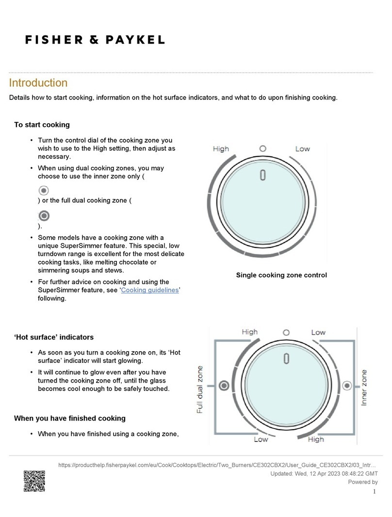
1-800-888-8018 or 615-537-3600
Fax 1-888-812-9956
www.aladdintemprite.com
MODEL IND600
Heat On Demand®ULTRA
HEAT ACTIVATOR & BASE
Manual P/N 98862
Rev. H 3/03/2009 INSTALLATION OPERATION & SERVICE MANUAL
Heat On Demand®U.S. Patent# 5 306 858 and 5 786 643 and 6 005 233 and 6 188 053
Japanese Patent# 3362855 other U.S. and Foreign Patents Issued and Pending

Copyright © 2007 Aladdin Temp-Rite®
Changes may be made to the information in this document without notication.

IND600 QUICK REFERENCE SHEET
ht9
“HEATING” unit is heating the Aladdin base
Steady during heating
rdy
“READY” base has completed its activation and is ready for use
Flashes at end of the heating cycle
Err
“ERROR” check LED error lights and service status for error code
Error codes can be found in the trouble shooting section
E02
Tray too hot or base has already been heated
Check tray temperature
Base is too cold to achieve proper retention
Remove base and set aside for 10 minutes then reinsert
Base has been removed before heating cycle was complete
Place base aside to cool for 10 minutes then reinsert
Unit has detected the base is not centered correctly
Remove base and reinsert into centering device


FOR PARTS & SERVICE CALL 1 (800) 888-5426
5
CONTENTS
IND 600 Heat On Demand®ULTRA SYSTEM
I. INTRODUCTION 6
II. SPECIFICATIONS 6
III. SAFETY 7
IV. REGULATORY COMPLIANCE & INDEPENDENT TESTING 7
V. RECEIVING INSPECTIONS 8
VI. INSTALLATION 9
ELECTRICAL CONNECTION 9
SETTING UP THE EQUIPMENT 10
REQUIRED CLEARANCE 10
PLUGGING THE UNIT IN 10
VII. OPERATION 12
DO'S and DON'TS 13
VIII. OPERATOR MAINTENANCE 14
SANITATION AND CLEANING PROCEDURES 14
IX. TROUBLESHOOTING 15
ERROR CODES 15
ELECTRICIAN’S TROUBLESHOOTING GUIDE 16
X. PARTS ILLUSTRATION 18
XI. PARTS LIST 19
XII. ELECTRICAL SCHEMATIC 20
XIII. BASE CARE AND HANDLING INSTRUCTIONS 21
HEAT-ON-DEMAND®ULTRA BASE CARE AND HANDLING 21
XIV. SERVICE 23
XV. WARRANTY AND LIABILITY 24

IND600 Heat On Demand®ULTRA SYSTEM Installation Operation
& Service Manual
FOR PARTS & SERVICE CALL 1 (800) 888-5426
6
I. INTRODUCTION
The Aladdin Temp-Rite Heat On Demand®Ultra Heat Activator is designed to provide a quick clean and
efcient heat source for use with the Aladdin Temp-Rite Heat On Demand® Ultra base.
The activator has been specically created for use O NLY with Aladdin Temp-Rite's Heat On Demand®Ultra
bases. There is no exposed coil open ame or heated surface. The only heat applied to the top surface of
the base is that which is absorbed from internal component base parts.
This activator contains no operator serviceable parts. Please consult a qualied electrician or the Aladdin
Temp-Rite Service Department should the equipment require service. Aladdin's toll free service line is
1-800-888-5426.
This product contains micro processor based componentry.
Potential voltages on the ground line or unstable electrical circuits may adversely affect the
operation of this equipment due to high frequency harmonics generated. Reliable grounding
practices prior to installation should be made to ensure line noise is minimized.
II. SPECIFICATIONS
MODEL NUMBER IND600
LENGTH 18.9”
WIDTH 17. 6 ”
HEIGHT 13.4”
VOLTAGE (with isolated ground) 208-240VAC
FREQUENCY 50/60HZ
PHASE 3
MAX AMPS DRAW 15
MINIMUM AMP CAPACITY 20
NEMA PLUG L15 - 20 P
WEIGHT 39 lbs
NUMBER OF WIRES 4
RECEPTACLE TYPE L15 - 20 R
i
! WARNING !
This equipment is to be installed only by a qualied electrician. There are
no operator serviceable parts inside this activator. Operators should never
remove the back panel or fuse access panel of this activator.

FOR PARTS & SERVICE CALL 1 (800) 888-5426
7
III. SAFETY
If you know how to correctly install operate clean and service the Heat On Demand®Ultra System
your satisfaction with the system will be increased and safety will be enhanced. In accordance
with generally accepted product safety labeling guidelines the following three signal words are
used throughout this manual to alert you to potential hazards and to tell you how to avoid them.
WARNING: The word "Warning" identies a potentially hazardous situation which if not avoided
COULD result in death or serious personal injury.
CAUTION: The word "Caution" identies a potentially hazardous situation which if not avoided MAY result in
minor or moderate injury. The word "Caution" may also be used to alert against unsafe practices
and property damage only accidents.
"Important" is used to identify installation operation or maintenance information which is
important but not hazard related.
Individuals with pacemakers are advised not to operate this product. To avoid
potential interference during operation, individuals with pacemakers, should maintain
a minimum distance of 24” (61 cm) from the unit.
IV. REGULATORY COMPLIANCE & INDEPENDENT TESTING
This equipment has been listed by the following organizations:
ETL to UL Standard 197 & National Sanitation Foundation - Standard Number 4
This equipment has been veried to comply with the following:
Code of Federal Regulations Title 47 Section 18 Federal Communications Commission
Code of Federal Regulations Title 29 Section 1910.97. Occupational Safety and Health Administration
Each user is responsible for adherence to existing local codes regarding the posting
of warning notices.
i
i

IND600 Heat On Demand®ULTRA SYSTEM Installation Operation
& Service Manual
FOR PARTS & SERVICE CALL 1 (800) 888-5426
8
This equipment generates uses and can emit radio frequency energy and if not installed and used
in accordance with these instructions may cause harmful interference to radio communications
devices. Changes or modications to this equipment not expressly approved by the party
responsible for compliance could void the user's authority to operate this equipment.
There is no guarantee however that interference will not occur in a particular installation. If
this equipment is found to cause harmful interference to radio communications the user is
encouraged to correct the interference by one or more of the following means:
A. Reorient or relocate the receiving antenna.
B. Increase the separation between the equipment and the receiver.
C. Connect the equipment into an outlet or on a circuit different from that which the receiver
is installed.
D. Consult your sales representative Aladdin Temp-Rite Service Department or an
experienced radio/TV technician.
NOTICE
V. RECEIVING INSPECTIONS
Your Aladdin IND 600 Heat On Demand Ultra Activator is factory tested for performance and is
free from defects when shipped. The utmost care has been taken in packaging this product to
protect against damage in transit.
You should carefully inspect your IND 600 Activator to assure that no damage has occurred
in transit. If however damage is detected see the following damaged goods policy. Under no
condition may a damaged unit be returned to Aladdin Temp-Rite without rst obtaining written
permission (return authorization). No credit will be issued for claims not reported to Aladdin
within ten (10) business days from receipt of shipment.
ALADDIN DAMAGED GOODS POLICY
There are two types of damaged merchandise:
A. VISIBLE DAMAGE OR SHORTAGE
B. CONCEALED DAMAGE
A. VISIBLE DAMAGE OR SHORTAGE - (All claims should be reported within 10 business
days)
1. Receiver should refuse the damaged portion of the shipment.
2. Receiver should sign the bill of lading indicating (delivery receipt) what merchandise is
being “refused due to damage” and have the driver initial the notation.
3. Receiver should note any shortages on the bill of lading (delivery receipt) in the same
manner.
4. Receiver should contact Aladdin Customer Service at 1-800-888-8018 and alert them to
FOR PARTS & SERVICE CALL 1 (800) 888-5426
9
the situation.
B. CONCEALED DAMAGE- (All claims should be reported within 10 business days)
Any receiving operation should inspect for this type of damage.
IF PRODUCT IS DAMAGED
1. Receiver should hold the shipping container and its contents in the same condition as when
the damage was discovered insofar as possible and call the delivering carrier to arrange on
site inspection within 10 days of delivery.
2. Receiver should contact Aladdin Customer Service at 1-800-888-8018 for claims
processing after inspection has been completed.
VI. INSTALLATION
This product contains micro processor based componentry.
Potential voltages on the ground line or unstable electrical circuits may adversely affect the
operation of this equipment due to high frequency harmonics generated. Reliable grounding
practices prior to installation should be made to ensure line noise is minimized.
This equipment is to be installed only by a qualied electrician. Installation Instructions
may be obtained from the Aladdin Temp-Rite Technical Services Department toll free
at 1-800-888-5426.
The installer should verify the proper operation of the unit as described in the following sections.
ELECTRICAL CONNECTION
Refer to Section II Specications data or the equipment data plate (located on the side of
the unit) your local codes and the National Electrical Code to be sure the ACTIVATOR is
connected to the proper power source. A protected circuit of the correct voltage and amperage
must be available for the connection of the power cord.
i
! WARNING !
Each Activator is tted with a grounded power cord and must be connected to a properly grounded
receptacle. Each receptacle must be wired to a dedicated circuit protected by a circuit protection
device rated at not more than 20 amps. If the Activator is not grounded a signicant electrical
shock hazard will exist.
To prevent electrical shock hazard turn the main power switch to the OFF position (No LED) and
disconnect the Activator from the power source whenever performing service or maintenance
functions. Always turn the Activator OFF (No LED) and disconnect it from the power supply prior
to removing the rear vented access panel. It is necessary to do this to prevent electrical shock
while performing service.

IND600 Heat On Demand®ULTRA SYSTEM Installation Operation
& Service Manual
FOR PARTS & SERVICE CALL 1 (800) 888-5426
10
PLUGGING THE UNIT IN
After setting the activator in place and insuring the unit has the proper
clearance plug the activator into the proper electrical outlet. Make sure to
lock the plug in place with a quarter turn clockwise.
TURN ON THE UNIT
The activator has a power switch located on the front right side of the control panel. Read the
following Operation sections of the manual before turning the activator on.
After turning on the activator the red LED next to the power button should
come on and the display show “___” & “___”. If the power LED or display
does not operate as described above the installer should
call the Aladdin Temp-Rite Service Department at 1-800-
888-5426.
To check the heating cycle slide a room temperature base into
the centering guides to activate the unit and verify that “ht9”
is displayed for approximately 12 seconds. At the end of the
heating cycle “rdy” should ash and beep twice
. If this does
not happen call the Aladdin Temp-Rite Service Department
at 1-800-888-5426.
SETTING UP THE EQUIPMENT
The activator has been completely checked at the Aladdin factory prior to shipment to you. No
adjustments of any sort should be required to place the activator into service. The activator
should be located in a position convenient to the tray line operator and within 6 feet of the
prescribed electrical outlet. The activator should be placed on a sturdy table capable of
supporting a minimum of 100 pounds safely (The table should support more weight if anything
else such as Heat On Demand Ultra bases are to be placed on the table). You may obtain
Model# IHAT98 "Table for Heat Activator" from Aladdin which has been designed specically
for use with this system.
REQUIRED CLEARANCE
Insure there is at least 6 inches of clearance between the activator and any combustible
materials such as paper plastic or cardboard. Insure there is also 6 inches clearance from the
rear panel so air ow through the activator is not obstructed. Insure that the unit is at least
36 inches from any source of steam.
! WARNING !
To prevent the possibility of re place the activator at least 6 inches from
any combustible material with no obstructions within 6 inches of the rear
vented access panel

FOR PARTS & SERVICE CALL 1 (800) 888-5426
11
CHECk SURFACE TEMPERATURES
Finally, the installer should verify the temperature of the Heat On Demand Ultra Bases. A surface
probe and digital thermometer such as Aladdin’s Model # TM97SPT and TM97DT should be used
to measure the surface temperature. Infrared thermometers, needle probes or grill thermometers
are NOT to be used. They will not provide an accurate measurement. Sixty (60) seconds after the
base has been activated (heated) on the unit for 12 seconds the outer perimeter of the base as
shown below, should be no less than 225°F (107°C) and should be at least 265°F (129°C). Starting
surface temperatures should be a minimum of 75°F (24°C). If this is not the case notify the Aladdin
Temp-Rite Service Department
at 1-800-888-5426
. Temperatures below 225°F (107°C) can impact
system performance.
Surface Temperature
Measurement Area
Minimum Temperature: No less than
225°F (107°C)
High Temperature: At least 265°F (129°C)
Guidelines for Best Food Temperature Holding Times
• Room temperature should be a minimum of 75°F (24°C).
• Aladdin’s Allure insulated dome is preferred.
• The base surface and Allure dome surface should be at least 75°F (24°C).
• China plate with a surface temperature of 165°F (74.°C) is preferred.
• Use 11oz of food with a minimum temperature of 165°F (74.°C)
• Place the Allure dome on the base within one (1) minute after heating the base.

IND600 Heat On Demand®ULTRA SYSTEM Installation Operation
& Service Manual
FOR PARTS & SERVICE CALL 1 (800) 888-5426
12
VII. OPERATION
No base should be on the activator surface when rst powering the
unit up. This may cause an “
Err”
message.
A.The activator has a power switch on the front right
side of the control panel. After turning on the activator the
red LED next to the power button should come on and the
display should show “___” & “___”.
1. Operator must place an unheated Heat On Demand
Ultra base in the proper location to start the heating
cycle. To do this slide the base into the self-centering
base guides until the heat activation switch is fully
depressed.
2. When the heater activation switch is depressed the display will beep once and “ht9” will
appear indicating the activator is heating.
Do not remove or tamper with the base during the heating cycle (while
“ht9” is displayed). Otherwise the activator will automatically stop heating
the Removed Early LED will illuminate and 5 beeps will sound.
3. At the end of the heating cycle “ht9” will be replaced by “rdy” blinking on the display and
beep twice to signal the base has completed its activation and is ready for use.
NOTE! “rdy” will blink on the display as long as the heated base remains in position.
4. The sequence of operation for this equipment is designed to activate a base in 12 seconds.
5. Always turn the main power switch to the "OFF" (Power LED and display dark) at the end of
each meal assembly period.
i
i
activation switch

FOR PARTS & SERVICE CALL 1 (800) 888-5426
13
DO'S and DON'TS
ALWAYS (DO'S) NEVER (DON'TS)
1Heat only Aladdin Heat On Demand®Ultra
bases (Ultra bases have "ULTRA" on the
bottom side of the base)
2 When calling Aladdin for service refer to
Model Number IND 600 and Serial Number
shown on the Data Plate on the right side
of the unit.
3 Power down the activator after each
meal service has been completed.
4Allow the heating cycle to nish before
removing the base.
1Never strike activator surface with sharp objects
or heavy weights.
2Never cover bottom of base during activation with
paper cloth foil or other material.
3Never place activator for operation near other
equipment with remote controls.
4Never attempt to heat any metal objects or bases
other than Aladdin Heat On Demand Ultra bases.
5Never heat an Aladdin Heat On Demand Ultra
base that has been heated within the past hour.
6Never heat Aladdin Heat On Demand Ultra
Bases in the microwave oven.
7Never stack bases after activation.
8Never heat a base with a dish in it.
9Never power up the activator with a base present
on the surface. The
“
Err” message will ash
and the unit must be reset without the base
present
10 Never strike Aladdin Heat On Demand®Ultra
bases against any hard surface to clean.
(Use caution when scraping base prior to
warewashing.)
11 Never heat an Aladdin Heat On Demand®Ultra
base missing the pressure relief poppet. Any
base found without a poppet should be removed
from service.
See Base Care & Handling for more
information
12 Never allow water to rest on the surface of the
activator. Make sure all bases are dry before
activating.
13 Never use bases that purge steam and expel
water onto the surface of the activator.

IND600 Heat On Demand®ULTRA SYSTEM Installation Operation
& Service Manual
FOR PARTS & SERVICE CALL 1 (800) 888-5426
14
VIII. OPERATOR MAINTENANCE
To prevent electrical shock hazard the power button must be in the OFF position before cleaning the
Activator.
The operator should never open the back panel or fuse access panel of this activator due to possible
electrical shock hazard. The back panel should only be opened by a qualied electrician who has read
the service and installation manual.
This activator is not hose washable. Clean only as directed above. Spraying with a hose can get water
into the electrical components and cause a short circuit or an electrical shock.
! WARNING !
To prevent damage to the top surface do not use harsh chemicals or under-diluted sanitizers.
Never
use bleach or solutions containing bleach to clean the stainless steel portions of the activator. The use of
this type of product can induce rusting.
! CAUTION !
SANITATION AND CLEANING PROCEDURES
1. Because the top surface remains relatively cool soil on the top of the activator will not "cook" onto
the top resulting in a quick and easy cleanup.
2. The Heat On Demand®Ultra activator should be cleaned and sanitized after each day's use or as
necessary by the following method.
a. Wipe the top and sides with a clean damp cloth using warm water and mild dishwashing deter-
gent. (Abrasive pads are not recommended for cleaning)
b. Use a soft nylon brush on any food soil and in corner areas.
c. Dry thoroughly with a clean dry cloth to remove moisture.
d.
Inspect and clean the air intake lter (see Section IX Parts Illustration)
located on the bottom of the Activator in the front with warm water and
mild detergent once each month or more frequently if it is heavily soiled.
To remove the air intake lter turn the activator off and disconnect it from
the power source. Pull the lter from the bottom front of the appliance.
No tools are necessary. The air intake lter may be immersed in water or
run through a dish machine. Insure that it is thoroughly dry before placing
it back in the activator
Do not operate activator with the air intake lter removed. Foreign particles could enter the activator and
cause an electrical failure. If the activator is operated without the air lter in place it is possible for a person
to stick their ngers in the moving fan blade and cause personal injury.
! WARNING !

FOR PARTS & SERVICE CALL 1 (800) 888-5426
15
IX. TROUBLE SHOOTING
E02
Base too hot or base has already been heated
Action Check base temperature
E03
Heat sink temperature too high
Action Check for air ow at back of unit air lter obstruction or heat sink fan for
failure
E04
Coil overheating
Action Check for air ow at coil, check coil fan connections, product may be
located too close to ovens, steam tables or fryers
E06
PCB board overheating
Action Check for air ow at back of unit, check air lter, verify heat sink fan is
operating, product may be located too close to ovens, steam tables or
fryers
E10
Communication error
Action check wiring between display and generator reset main power by
turning off unit and unplugging. Possible power problem due to loss of
phase or low voltage.
E25
Coil temperature sensor broken
Action Check coil temperature sensor connection
Only a qualied electrician should work on the activator.
Error Codes:
Displayed in the window.
i

IND600 Heat On Demand®ULTRA SYSTEM Installation Operation
& Service Manual
FOR PARTS & SERVICE CALL 1 (800) 888-5426
16
Fasteners used in the activator are metric. Any attempt to replace metric fasteners with
English fasteners could result in stripped threads or improperly afxed components.
To prevent electrical shock hazard the vented rear access panel must be opened only by a qualied
electrician. Prior to performing any maintenance service or removing the vented rear access panel
insure the activator is turned OFF and is disconnected from the electrical supply.
! WARNING !
i
Electrician’s Troubleshooting Guide
No. MALFUNCTION CAUSE SOLUTION
1. No power indicator light Main power button is OFF Turn on main power
Improper electrical plug
connection
Insert and twist plug quarter turn clockwise check
receptacle
Blown 20 amp main fuse Replace (at rear of unit) (PN 98914)
Power outage Call facilities maintenance
2. Base does not start to heat
(“ht9” not displayed)
Incorrectly positioned base Position base snugly against alignment xture so that
the switch is fully depressed.
3. Base does not nish heating
( “Err” displayed)
Incorrectly positioned base Remove original base. Next correctly reposition a
new base in alignment xture. (Do not double cycle
the same base) If activator does not operate properly
after resetting call Aladdin Temp-Rite Service Depart-
ment.
4. Activator will not run (“
Err”
displayed)
Incorrect voltage Check voltage at receptacle. Voltage should be +/-
10% at each phase.
Interrupted power Reset unit: Turn the unit OFF wait 10 seconds & turn
the unit back on.
Incorrectly positioned base Slide the base snugly against alignment guide so that
activation switch is fully depressed.
Inserting the base in the alignment guide at an angle
can create a situation where the activator thinks it
should begin a heating cycle. However the base
may not be properly seated on the IND600 surface.
Base in pellet guide upon
power up
Always remove base from pellet guide upon initial
power up of appliance.
Broken switch
(Visibly Noticeable)
Call a Service Technician to check if activation switch
is broken. Replace switch (p/n 97860) if necessary.
Broken switch
(Not visibly noticeable)
Call a Service Technician to check the activation
switch with an ohm meter ≤10 Ωis normal. Replace
switch (p/n 97860) if necessary.
COLD LED is illuminated Base is too cold to achiever
proper retention
Remove base and set aside for 10 min then reinsert
REMOVED EARLY LED is
illuminated
Base removed early Reinsert base may be too hot after removing early.
ALIGNMENT LED is
illuminated
Base not properly aligned in
guides
Check alignment of base in guides.
Electrician’s Troubleshooting Guide
Fig. A*
Fig. C*
Fig. B*
Fig. A*
Fig. A*

FOR PARTS & SERVICE CALL 1 (800) 888-5426
17
Electrician’s Troubleshooting Guide
No. MALFUNCTION CAUSE SOLUTION
5. Activator stops suddenly
(Power LED goes out)
Power cord has become
unplugged
Plug back in to receptacle with a quarter turn
clockwise
Power outage Call Facilities Maintenance
Do not double cycle base. Reset activator
by turning power switch OFF waiting 10 seconds
then turn power switch back on. If activator does not
operate properly after resetting call Aladdin Service
Department.
6. Top is excessively hot (Over
200˚F) shuts off
Missing air lter Replace air lter immediately
Dirty air lter Clean air lter monthly or more frequently if
heavily soiled.
7. Activator suddenly stops and
will not re-start
Power outage Call facilities maintenance.
8.
“ht9” is not displayed for
approximately 12 seconds.
Base has been heated within
the past hour and is still hot.
Use another Aladdin Heat On Demand®Ultra base
Previous base was pulled out
before cycle ended
Allow each base to remain in the alignment guide for
the entire heating cycle.
9. “E02” is immediately
displayed after inserting the
base
Base has been heated within
the past hour and is still hot
Use a cool (room temp.) Aladdin Heat On Demand®
Ultra base.
10. Low base temperature
(<230˚F on outer edges
60-90 seconds after
activation)
Refer to section VI in manual
Measuring base temperature
in the wrong location
Check temperature in proper location (see section
VI)
Measurement device in error Verify calibration of device
Fig. A
Fig. B
Fig. C
Fig. D
Fig. D
Fig. D

IND600 Heat On Demand®ULTRA SYSTEM Installation Operation
& Service Manual
FOR PARTS & SERVICE CALL 1 (800) 888-5426
18
X. PARTS ILLUSTRATION
34
1
2
3
4
5
6
7
9
13
15
17
18
19
20
22
23
24
28
29
31
32
28
21
27
32
20

FOR PARTS & SERVICE CALL 1 (800) 888-5426
19
XI. PARTS LIST
Electrical parts illustrated on the parts illustration wiring schematic and parts list are for
purposes of illustration only. Only the parts listed are replaceable in the eld by a qualied
electrician. All other service work will require that the Activator be returned to the Aladdin
factory for service. Should the Activator have to be returned for service to the Aladdin factory
contact the Aladdin Temp-Rite Service Department for information regarding the availability of a
"loaner".
ITEM PART # DESCRIPTION QTY
198913 AIR FILTER 1
298493 BASE PLATE ULTRA 1
398903 COIL 1
498902 FAN COIL 1
598901 COIL BOLT 4
698934 GLASS, REPLACEMENT ASSY
(GLASS, TOP COVER, SWITCH, 4 GUIDES, OVERLAY, FRONT LABEL)
1
798907 DISPLAY / CONTROLLER 1
8* 98908 EMI FILTER 1
975074 FOOT BASE CONICAL RUBBER 4
10* 98916 FUSE 250V 1A 1
11* 98914 FUSE 250V 20A 3
12 - - -
13 98497 GUIDE BASE 4
14* 98906 HARNESS COMMUNICATION 1
15 98909 FAN HEAT SINK 1
16 - - -
17 98564 GENERATOR 5KW ASSY 1
18 98885 LABEL MIN CLEARANCE HOD 1
ITEM PART # DESCRIPTION QTY
19 98516 LABEL FRONT ULTRA 1
20 99070 M4 NYLOC NUT -
21 97315 O-RING SIZE 009 SILICONE -
22 98512 OVERLAY DISPLAY 1
23 98495 PANEL BACK ULTRA 1
24 98915 PLUG 1
25* 98917 POWER CORD (WIRE ONLY) 1
26 - - -
27 92068 SCREW 10-14-1/2”THRD FR -
28 97817 SCREW 10-32X1/2 -
29 98905 SPRING -
30* 98900 STRAIN RELIEF 1
31 97860 SWITCH ACTIVATION 1
32 28125 WASHER #10 FLAT S/S -
33* 98927 KIT GUIDE AND O RINGS 4
34 98904 COIL SCREW 4
* items not shown

IND600 Heat On Demand®ULTRA SYSTEM Installation Operation
& Service Manual
FOR PARTS & SERVICE CALL 1 (800) 888-5426
20
Electrical parts illustrated on the parts illustration wiring schematic and parts list are for
purposes of illustration only. Only the parts listed are replaceable in the eld by a qualied
electrician. All other service work will require that the Activator be returned to the Aladdin
factory for service. Should the Activator have to be returned for service to the Aladdin factory
contact the Aladdin Temp-Rite Service Department for information regarding the availability of a
"loaner".
XII. ELECTRICAL SCHEMATIC
SERVICE SPECIFICATIONS: 208VAC/20AMP/3PHASE/60HZ
1.TWIST WIRES WHERE POSSIBLE (L1/L2/L3)
AMBER
PURPLE
COLOR
BLUE
YELLOW
BROWN
WHITE
BLACK
ORANGE
RED
AMB
PRP
BLU
YEL
BRN
WHT
BLK
2.
ABBR.
RED
ORG
NOTES
GREEN
GRAY
BROWN
BRN
GRY
GRN
GRN: EARTH GND
L3
L2
GND
PLUG: NEMA L15-20P
EMI FILTER
BLK
RED
BLK
WHT
RED
LINE
LOAD
BLK
BLK
BLK
POWER BOARD
COIL
H1
H2
H3
L2
L3
L1
I117
DISPLAY COMM. CABLE
L1
L2
L3
57uH
Electrical Diagram IND600
FUSE 250VAC/1A
DISPLAY
+
-
RED
ORG
YEL
BRN
FAN
I130
SWITCH
CYCLE
T-STAT
-
BLK
+
-
+
WHT
ORG
REDBLK
RED
USED
CONTROL BOARD
SINK
HEAT
67 Ohms@ 72F
FAN
COOLING
COIL
NOT
USED
NOT
BOARD
I152
RED
ORG
YEL
BRN
RED WHT
POWER: 208VAC / 15A / 60HZ / 3 PHASE
Audio OFF (Jumper Set)
DISPLAY
COIL
FUSE 250VAC/20A
FUSE 250VAC/20A
FUSE 250VAC/20A
5kW
24VDC 24VDC
Audio ON (No Jumper)
Jumper Set
No Jumper
No Jumper
L1
WHT
>1.250-
*UNLESS OTHERWISE INDICATED
GENERAL TOLERANCES - LINEAR DIMENSIONS - VARIATIONS IN INCHES
USED ON
VARIATIONS*
PERMISSABLE
(PLUS OR MINUS
INDICATED VALUE)
ANGULAR TOLERANCE IS +/- 30'*
PAGE #VENDOR
DATEDRAWN BY:
BASIC DIMENSIONS
A
B
C
D
X
>.125-
+/- 1/32"
.008
.004.004
.002.002
.250.125
.020-
.015
.030
.012
.006
5.000
.050
.020
.008
.004
1.250
.030
>.250-
ALADDIN synergetics inc.
ECN
NOTICE: THIS DRAWING IS THE PROPERTY OF
ALADDIN SYNERGETICS, INCORPORATED AND
CONTAINS PROPREITARY INFORMATION OWNED
BY THAT COMPANY. IT IS NOT TO BE USED
EXCEPT IN THE CONSIDERATION OF BIDS OR
IN WHOLE OR IN PART, IS STRICTLY PROHIBITED.
REPRODUCTION OR COPYING OF THIS DRAWING,
PROPOSALS TENDERED HEREWITH.
.080
.125
.030
.012
>12.000-
40.000
.050
.020
.008
12.000
>5.000-
.080
.125
.050
.020
>40.000-
80.000
.200
REV. DATE DESCRIPTION BY
Part No.:
Title
Nashville, TN
Scale: Sheet
Dwg. No.:
Sales Code:
of
IND600 ELECTRIC DIAGRAM
NONE
RDC 7/23/07
ELECTRIC
IND600 elect.
1 1
IND600
A DRAWING RELEASE7/23/07 RDC
IND600
+
-
N/O
Table of contents