Albalá Ingenieros, S.A. HVD3001C02 User manual
HVD3001C02
DUAL 1 INPUT TO 6 OUTPUTS 3G/HD/SD-SDI DIGITAL VIDEO DISTRIBUTOR
(ONE SAFE OUTPUT PER SECTION) AND WITH FRONTAL OPTICAL INPUTS
AND OUTPUTS WITH OPTIONAL PLUGGABLE SFP MODULES
Version 1.0
Albalá Ingenieros, S.A.
Medea, 4 - 28037 Madrid - Spain
20 May 2015 - © Albalá Ingenieros S.A. - All rights reserved

HVD3001C02

When the module incorporates any optional
SFP/SFP+ optic fiber transmitter provided by
Albalá Ingenieros, the HVD3001C02 is a CLASS 1
LASER product as per the IEC 60825-1 standard.
Please read the safety instructions included in
this manual carefully before using this module.

HVD3001C02

HVD3001C02
DUAL 1 INPUT TO 6 OUTPUTS 3G/HD/SD-SDI DIGITAL VIDEO DISTRIBUTOR
(ONE SAFE OUTPUT PER SECTION) AND WITH FRONTAL OPTICAL INPUTS AND
OUTPUTS WITH OPTIONAL PLUGGABLE SFP MODULES
Version 1.0
1. DESCRIPTION ...................................................................................................................... 7
1.1. The HVD3001C02 ........................................................................................................................... 7
1.2. Features ............................................................................................................................................. 9
1.3. Block diagram ............................................................................................................................... 10
2. SPECIFICATIONS ............................................................................................................... 11
3. INSTALLATION .................................................................................................................. 13
3.1. Initial inspection .......................................................................................................................... 13
3.2. Safety instructions ...................................................................................................................... 13
3.3. Environmental considerations ................................................................................................ 14
3.4. Power considerations ................................................................................................................. 14
3.5. Installation of SFP/SFP+ modules .......................................................................................... 15
3.6. Installing the module in the mounting frame ................................................................... 15
3.7. Interconnection ............................................................................................................................ 17
3.7.1. Electrical SDI video connections .................................................................................... 18
3.7.2. Optical SDI video connections ........................................................................................ 18
4. OPERATION ...................................................................................................................... 19
4.1. Front panel description .............................................................................................................. 19
4.2. Configuration ................................................................................................................................ 20
4.3. Module remote control and supervision ............................................................................. 21
4.3.1. Details of the HVD3001C02 registers .......................................................................... 22
5. GLOSSARY ........................................................................................................................ 25
6. REGULATIONS .................................................................................................................. 27
7. VERSIONS ......................................................................................................................... 29

HVD3001C02

Albalá Ingenieros | Manual HVD3001C02
1. DESCRIPTION
1.1. The HVD3001C02
The HVD3001C02 module is a dual digital video distributor for SDI format signals at
3Gbit/s (3G), 1.5Gbit/s (HD) and 270Mbit/s (SD) with automatic cable equalization and
reclocking functions. The module consists of two independent sections, each of which
has one electrical input and six electrical outputs. In addition, electrical-to-optical and
optical-to-electrical SFP modules can be installed in order to add fiber optic connectivity
to each section. Also, the two sections can be combined for use a as a single channel
distributor with one input and 12 outputs.
The HVD3001C02 can also distribute DVB-ASI signals however in this case the number of
electrical outputs is reduced by one half.
The SFP converter modules are optional. Up to two can be added - one for the input and
one for the outputs. Each module has two independent channels, one per section.
The fiber optic inputs and outputs of the HVD3001C02 module connect at the front
panel, allowing up to six outputs per section.
The HVD3001C02 includes one bypass relay per section on the rear board that connect
the electrical input of each section to one of that section´s electrical outputs in case of
power loss or extraction of the module from the mounting frame.
The HVD3001C02 includes the following status LEDs for each section: input failure,
de-sync of the reclocker and failure of the SFP module laser (if an SFP is inserted). In
addition there is an LED to indicate HD signals and two more LEDs to indicate if the input
is electrical or optical.
It is possible to monitor the HVD3001C02 status remotely using a communications
controller module installed in the same mounting frame. In addition, certain controller
modules provide SNMP management and the ability to record events in a file including
date and time information for further analysis.
The HVD3001C02 is a TL3000 terminal line module and can be housed in a three rack
unit (3 RU) UR3000 mounting frame or a 1 RU UR3100 mounting frame.
The HVD3001 family encompasses the following range of 3G/HD/SD-SDI signal
distributors:
•HVD3001C01: A dual 3G/HD/SD-SDI signal distributor with one input and six outputs
and capability for optical inputs and outputs via optional, front panel SFP modules.
•HVD3001C02: A dual 3G/HD/SD-SDI signal distributor with one input and six outputs
7

Albalá Ingenieros | Manual HVD3001C02
and capability for optical inputs and outputs via optional, front panel SFP modules. One
electrical output is protected with a bypass relay.
•HVD3001C03: A dual 3G/HD/SD-SDI signal distributor with one input and four outputs
and capability for optical inputs and outputs via optional, front panel SFP modules.
•HVD3001C04: A dual 3G/HD/SD-SDI signal distributor with one input and four outputs
and capability for optical inputs and outputs via optional, front panel SFP modules. One
electrical output is protected with a bypass relay.
The following optional, fiber optic SFP modules are available from Albalá Ingenieros:
- MSFPTP01 transmitter.
- MSFPRP01 receiver.
- MSF-CWDC01 transmitter.
- MSF-CWDC02 transmitter.
- MSF-CWDC03 transmitter.
- MSF-CWDC04 transmitter.
- MSF-CWDC05 transmitter.
- MSF-CWDC06 transmitter.
- MSF-CWDC07 transmitter.
- MSF-CWDC08 transmitter.
- MSF-CWDC09 transmitter.
8

Albalá Ingenieros | Manual HVD3001C02
1.2. Features
• Dual 3G/HD/SD-SDI digital video signal distributor.
• Provides two sections, each equipped with:
- One 3G/HD/SD-SDI electrical input.
- One front panel 3G/HD/SD-SDI optical input when optional SFP module is installed.
- Six 3G/HD/SD-SDI electrical outputs.
- One front panel 3G/HD/SD-SDI optical output when optional SFP module is installed.
•Each section provides a bypass relay on the rear board that enables the input signal to
be passed through to one of the outputs in case of power loss or module removal.
•Also distributes 270Mbit/s DVB-ASI signals but in this case the number of usable
outputs is reduced by one half.
•Provides cages for SFP modules allowing addition of optical inputs and outputs to the
distributor.
• Can be configured as one sole distributor in order to double the number of outputs.
• Provides automatic cable equalization at the input capable of compensating up to:
- 300 meters of Belden 1694A at 270Mbit/s.
- 180 meters of Belden 1694A at 1.5Gbit/s.
- 110 meters of Belden 1694A at 3Gbit/s.
• Includes reclocking.
• The distributor does not process the content of the video signal.
•Module control and supervision can be done remotely when the mounting frame is
equipped with a communications controller module.
•One UR3000 mounting frame can house up to 12 HVD3001C02 modules. If power
supply redundancy is required and FA3000 or FA3001 modules are used then only 10
modules can be housed in the mounting frame. If PSU3300 or PSU3301 modules are
used for this purpose then up to 12 modules can be installed.
• One UR3100 mounting frame can house up to three HVD3001C02 modules.
• Low power.
9

Albalá Ingenieros | Manual HVD3001C02
1.3. Block diagram
10

Albalá Ingenieros | Manual HVD3001C02
2. SPECIFICATIONS
SD/HD/3G-SDI digital video signal input
Connector BNC
Impedance 75Ω ± 1 %
Return loss:
Up to 3 GHz >10 dB
Up to 1.5 GHz >15 dB
Input Return loss when bypass is active:
Up to 3 GHz >10 dB
Up to 1.5 GHz >15 dB
Output protected with bypass relay Yes
Number of inputs 1 per section, 2 sections
Equalizable cable length:
Belden 1694A, SD 270Mbit/s >300 m
Belden 1694A, HD 1,5Gbit/s >180 m
Belden 1694A, HD 3Gbit/s >110 m
SD/HD/3G-SDI digital video optical signal input
Connector LC/PC with multimode or monomode
fiber
Number of inputs 1 per section, 2 sections
SD/HD/3G-SDI digital video signal output
Connector BNC
Impedance 75Ω ± 1 %
Return loss:
Up to 3 GHz >10 dB
Up to 1.5 GHz >15 dB
Output return loss when bypass is active:
Up to 3 GHz >10 dB
Up to 1.5 GHz >15 dB
Input to output bypass insertion loss:
Up to 3 GHz <0.1 dB
Up to 1.5 GHz <0.1 dB
Number of outputs 6 per section
Amplitude 800mVpp ± 10 %
Rise and fall time (20 % - 80 %):
SD 270Mbit/s 650 ps typ.
HD 1.5Gbit/s 130 ps typ.
HD 3Gbit/s 130 ps typ.
11

Albalá Ingenieros | Manual HVD3001C02
SD/HD/3G-SDI digital video optical signal output
Connector LC/PC with monomode fiber
Number of outputs 1 per section
SD/HD/3G-SDI digital video signal
Signal formats According to SMPTE ST 424,
SMPTE ST 292-1, SMPTE ST 259
standards
Bit rates 270Mbit/s, 1.483Gbit/s,
1.485Gbit/s, 2.967Gbit/s
and 2.970Gbit/s
Accepted formats 625i50, 525i59.94,
720p50, 720p59.94,
1080i50, 1080i59.94,
1080p50, 1080p59.94
Input to output delay:
270Mbit/s 7 ns ± 1 ns
1.5Gbit/s 4 ns ± 1 ns
3Gbit/s 4 ns ± 1 ns
General
Maximum power supply current + 500 / - 600mA including SFP modules
Operating temperature range 0 .. 50 °C
Approximate weight 325 g
12

Albalá Ingenieros | Manual HVD3001C02
3. INSTALLATION
THE HVD3001C02 MODULE CONTAINS ELECTRONIC DEVICES SENSITIVE TO
ELECTROSTATIC DISCHARGE. Always use antistatic bags clearly identified
with a high degree of shielding for storage and transportation.
The HVD3001C02 module is composed of two parts: one HVD3001P01 main board and
one XVD3000P08 rear board. Both parts must be installed in a UR3000 or UR3100
mounting frame following the instructions in the corresponding section of this chapter.
3.1. Initial inspection
Verify that the package has been properly handled during transport. After opening the
packaging, check that one HVD3001P01 main board and one XVD3000P08 rear board
are inside.
You must notify your Albalá Ingenieros distributor or dealer of any damage or defects
observed.
Follow the instructions in this manual to install this module in the mounting frame.
3.2. Safety instructions
When the module incorporates any optional SFP/SFP+ optic fiber transmitter provided by
Albalá Ingenieros, the HVD3001C02 is a CLASS 1 LASER product as per the IEC 60825-1
standard. Please read the safety instructions included in this manual carefully before
using this module.
•The HVD3001C02 may contain an SFP/SFP+ fiber optic transmitter module
with laser diodes. These modules are CLASS 1 LASER products. Due to its
features this device is inherently safe. However, exercise CAUTION as there
is invisible laser radiation in the module's fiber optic connectors. Avoid
exposure to the beam. NEVER lift or remove the cover of the HVD3001C02's
optical connectors except to connect a fiber optic connection, and be sure
that the power is off when doing so. NEVER leave optical connections that
are carrying signals disconnected from the equipment. NEVER examine a
fiber optic connector with a microscope without being absolutely certain
13

Albalá Ingenieros | Manual HVD3001C02
that no optical signal is present, as this could cause serious damage to the
retina.
•This equipment must be connected to a mains outlet with a protective
earth connection. Never use extension cords that do not have protective
earthing connection. The lack of an effective electrical connection between
the ground pin in the mains input connector of the equipment and the
protective earth of the electrical power distribution can cause serious harm.
•All modules of the Albalá Ingenieros TL3000 terminal line can be
hot-plugged or unplugged without suffering any damage or affecting the
processes that are currently taking place in other modules in the same
mounting frame. When a module is installed in an empty bay of a mounting
frame, it is necessary to mount the rear board that is part of that module.
Prior to installing this board, the mounting frame must be disconnected
from the power supply network. This is required because in addition to the
risk of electrocution for the person handling the device it is possible that a
high instantaneous current coming from the power supply could damage
the connectors and components of the mounting frame and/or the rear
board.
•The HVD3001C02 module and the mounting frame should always be
installed, maintained, operated and removed by personnel with sufficient
technical qualifications. The equipment should never be placed in damp
areas, near splashing liquid, or in explosive or corrosive atmospheres.
Neither modules nor mounting frames can be used in applications that
could endanger human life.
3.3. Environmental considerations
This symbol indicates that this equipment must be deposited at a collection
point for proper waste treatment once it has reached the end of its useful
life.
3.4. Power considerations
The UR3000 and UR3100 mounting frames can house as many HVD3001C02 modules as
will fit in them.
14

Albalá Ingenieros | Manual HVD3001C02
3.5. Installation of SFP/SFP+ modules
The HVD3001C02 features receptacles to install optional SFP/SFP+ modules for signal
transmission or reception over optical fiber or other functions. To install or uninstall one
of these modules in the equipment, follow the instructions given below.
To install, insert the SFP/SFP+ module into the receptacle and slide it carefully until it
clicks, indicating that the module has reached its final position.
The HVD3001C02 features receptacles to install optional SFP+ modules for Ethernet
signal transmission or reception that are sold separately. To install or uninstall one of
these modules in the equipment, follow the instructions given below.
To uninstall, first remove any optical or electrical cables that are connected to the
SFP/SFP+ module. Then lift the metal ring located at the opening of the SFP/SFP+
module to disable the module's retention mechanism and release it. Finally, pull module
carefully out of its receptacle.
There are different types of SFP/SFP+ modules. Make sure that module to be installed is
appropriate for the receptacle that will contain it.
3.6. Installing the module in the mounting frame
The steps needed to install the HVD3001C02 module with the rear board in the
mounting frame are:
1 - Disconnect all power cords from the power supplies of the mounting frame.
2 - Remove the blank panels covering the front and rear of the empty bays chosen for
installing the HVD3001C02 in the mounting frame.
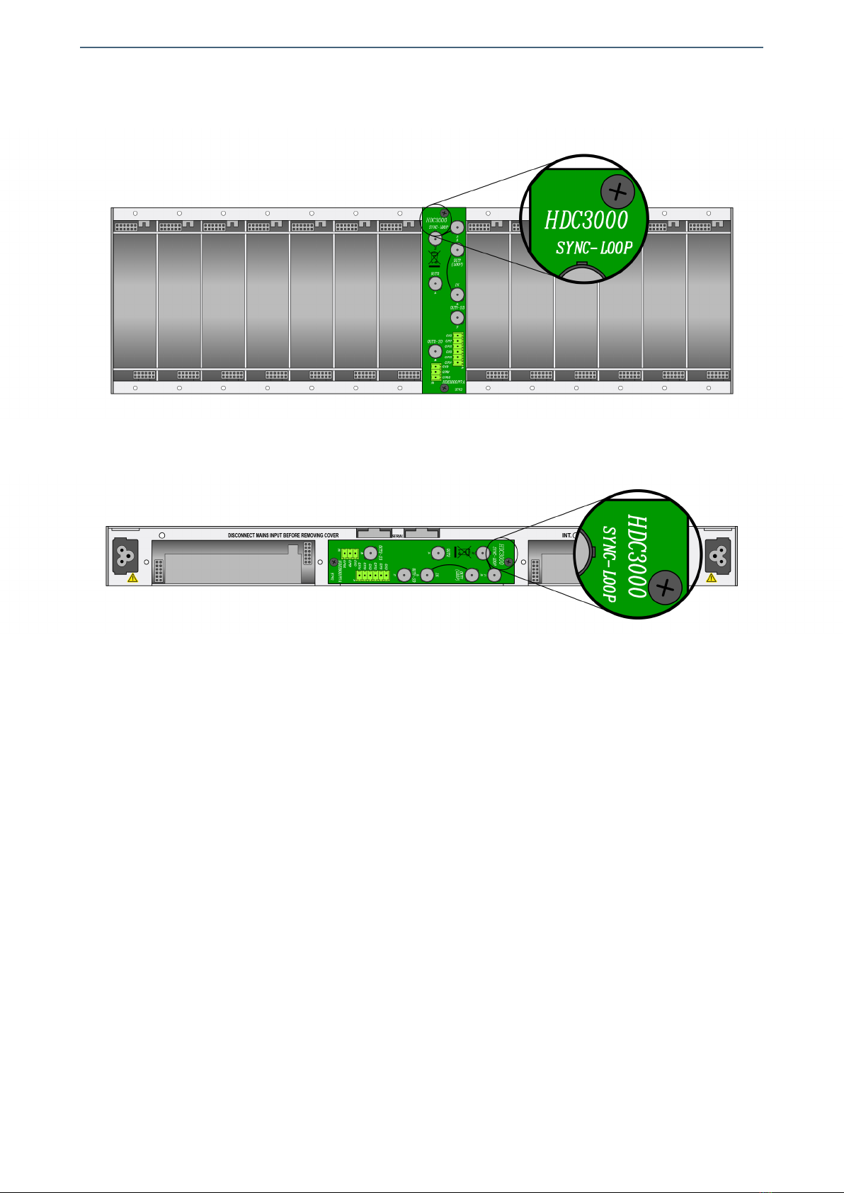
3 - Install the XVD3000P08 rear board ensuring that its 12-pin connectors are properly
aligned with the mounting frame´s mating connectors. Check that the orientation of
the board is correct by looking at the placement of the text printed on it according to
the illustration below.
4 - Attach the rear board to the mounting frame with two M3 metric screws and tighten.
5 - Insert the HVD3001P01 board (main board of the HVD3001C02 module) into the front
of the mounting frame. The edges of the card slide into two plastic guides inside the
mounting frame.
6 - Conector the two fiber optic LC connector pigtails coming from the rear board to the
SFP modules.
7 - Affix the main board to the mounting frame using the two screws included on the
front panel.
After these steps, the module is ready to be connected to other equipment.
15
Albalá Ingenieros | Manual HVD3001C02
Details for installation of the module in 3 RU mounting frames
Details for installation of the module in 1 RU mounting frames
16

Albalá Ingenieros | Manual HVD3001C02
3.7. Interconnection
The following figure shows the HVD3001C02 module rear board connector layout.
Rear view of the HVD3001C02
The HVD3001C02 module includes two inputs (IN A,IN B) and six outputs per section
(OUT0-A to OUT5-A,OUT0-B to OUT5-B) for 3G/HD/SD-SDI digital video. When
configured as a single channel one input, 12 output distributor only input IN A is used.
The HVD3001C02 modules includes bypass relays on the rear board that connect the
signal at the IN A input to the OUT0-A output and also from the IN B input to the OUT0-B
output in case of power loss or extraction of the module.
The HVD3001C02 also includes front-panel optical inputs and outputs (OPTICAL INPUT,
OPTICAL OUTPUT) for SDI video.
The HVD3001C02 also accepts 270 Mbits/s DVB-ASI signals. These signals are polarity
sensitive, and because half of the outputs of the distributor are polarity inverted, only
the non-inverted outputs marked as OUT0,OUT2 and OUT4 can be used in section A and
OUT1,OUT3 and OUT5 in section B.
17

Albalá Ingenieros | Manual HVD3001C02
The rear interconnection board is not designed to withstand mechanical stress. The
wiring must be fastened properly to the frame where the mounting frame is housed to
prevent the rear board from supporting the weight of the cables.
3.7.1. Electrical SDI video connections
All electrical SDI video connections are BNC type. The following suggestions should be
kept in mind when wiring the electrical signals.
BNC connectors used on cables must be suitable for the high frequencies of digital
video signals: it is strongly recommended to use high quality connectors from well
known manufacturers.
All coaxial cable used must be Belden 1694A or similar. This type provides the greatest
lengths because it is used to calculate the equalizers in the HVD3001C02. Cables
carrying signal between the module and the devices should use single piece
construction, avoiding spliced sections with double BNC female or barrel connectors.
If it is necessary to split the cable into two sections the same type of wire should be
used in both sections.
The use of analog video coaxial cables RG-59 type or similar is not recommended for
digital video except for very short distances.
3.7.2. Optical SDI video connections
The SFP/SFP+ fiber optic module must be inserted into its housing as described
previously before interconnection.
Optical connections are performed in the SFP/SFP+ module, which is equipped with
LC/PC connectors. Connectors using single-mode fiber optics are usually blue.
Connectors for multimode fiber optics are usually gray.
Singlemode fiber must be used in fiber optic cabling. However, for standard definition
and short lengths multimode fiber can be employed. Before connecting any fiber
optics, the cap that protects the connectors must be removed. Unused fiber optic
connectors should always be covered by the protective cap.
All fiber optic cables have a minimum curvature radius that must be obeyed (consult
the specification of the cabling used) and should be run with enough strain relief to
absorb small, unintended pulling or mechanical stress.
Fiber optic connections are sensitive to dust and dirt. Any dust or dirt particles trapped
in the optical pathway act as attenuators of unknown value and in the worst case can
render the signal unusable. Care must be taken to ensure the cleanliness of and not to
dirty the connectors during insertion and removal of the fiber optic cables.
18
Albalá Ingenieros | Manual HVD3001C02
4. OPERATION
This section describes the significance of the front panel indicators of the HVD3001C02
module and their remote control and monitoring ability.
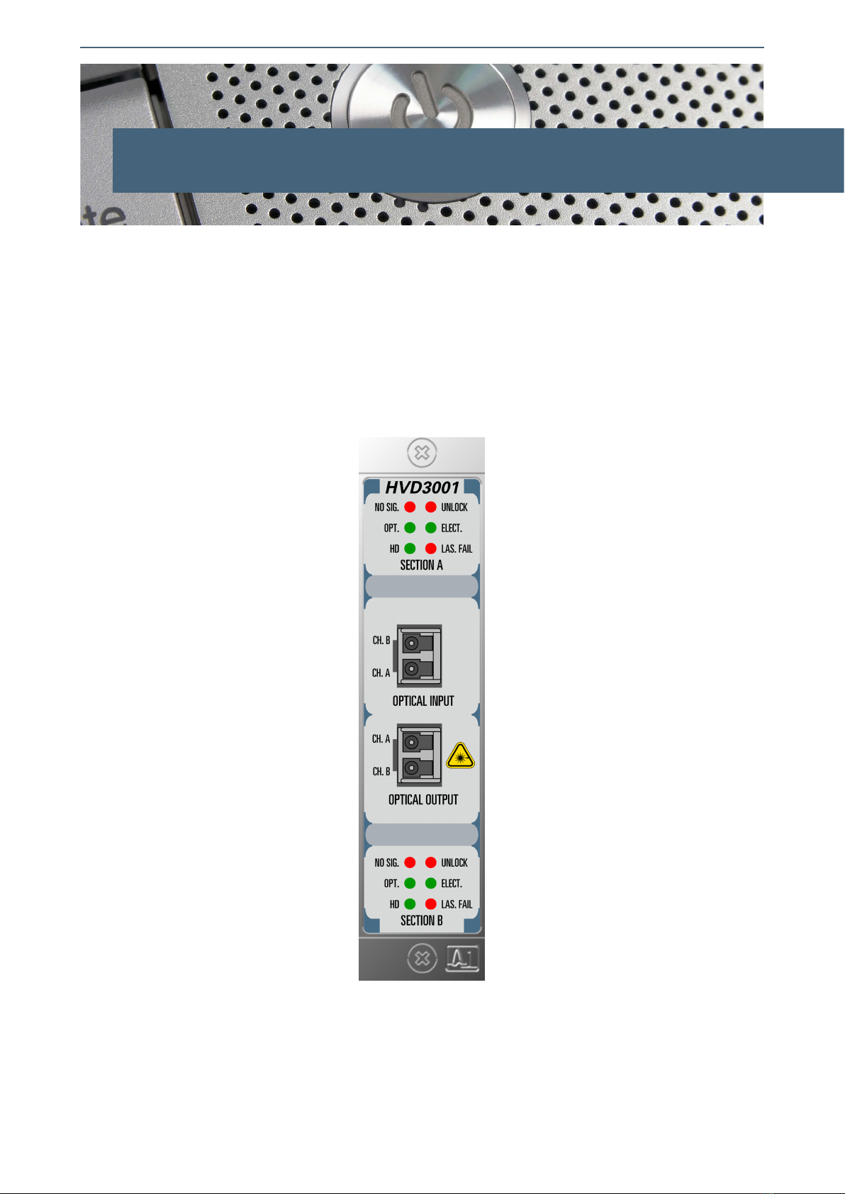
4.1. Front panel description
The appearance of the front panel and the elements it contains are shown in the
following illustration.
Front panel of the HVD3001C02
The panel contains the following elements:
19

Albalá Ingenieros | Manual HVD3001C02
In the SECTION A and SECTION B box:
NO SIG.: Red. This LED lights up when no input signal is present.
UNLOCK: Red. This LED lights up when the reclocker fails to lock to the input.
OPT.: Green. This LED lights up to indicate that the optical input has been
selected.
ELECT.: Green. This LED lights up to indicate that the electrical input has been
selected.
HD: Green. This LED lights up to indicate that the input signal is HD at
1.5Gbit/s or 3Gbit/s.
LAS. FAIL: Red. This LED lights up to indicate a failure in the laser of the
electrical-to-optical SFP converter module.
In the OPTICAL INPUT box:
CH.A/CH.B: Cage for the optical-to-electrical SFP converter module that provides fiber
optic connectivity for the inputs of both sections.
In the OPTICAL OUTPUT box:
CH.A/CH.B: Cage for the electrical-to-optical SFP converter module that provides fiber
optic connectivity for the outputs of both sections.
4.2. Configuration
The HVD3001C02 includes two sections and can function either as two independent one
input, six output (2x6) distributors or as a single one input, 12 output (1x12) distributor.
When operating as a single channel distributor the input for Section B is not used
(regardless of whether the input is electrical or optical) and the Section B indicator LEDs
remain off. If the optional electrical-to-optical SFP converter is installed the two optical
outputs carry the signal from Input A in optical format. The HVD3001C02 comes from
the factory programmed as a dual 2x6 distributor.
The HVD3001C02 can receive optical signals coded as per SMPTE ST 297 when an
optical-to-electrical SFP module is installed. The active input is always indicated by the
front panel LEDs. The HVD3001C02 comes from the factory programmed to distribute
the signal received at the electrical input.
The module can be configured remotely as described in the following section.
20
Table of contents
Other Albalá Ingenieros, S.A. Amplifier manuals


