!
E3X-NV/NVG E3X-NV/NVG
Precautions
WARNING
AVOID EXPLOSION OR FIRE
The voltage supplied to the E3X-NV/NVG must be within
the rated voltage range. If a voltage exceeding the rated
upper limit is imposed on the E3X-NV/NVG.
Connect each power line of the E3X-NV/NVG correctly.
Do not short-circuit the load connected to the E3X-NV/NVG.
TURNING POWER ON
After the E3X-NVis turned on, it will be ready to operate in 100 ms
maximum. If power is supplied to the E3X-NVand the load is con-
nected to the E3X-NVindependently, be sure to turn on the power
supply connected to the E3X-NVfirst.
When the E3X-NVis turned on or off, no control output will be ON,
even though the operation indicator of the E3X-NVwill be lit for an
instant.
MUTUAL INTERFERENCE PROTECTION
FUNCTION
When closely connecting two to three Fiber Units to more than one
E3X-NV, perform with/without-object teaching on a single E3X-
NVat a time. Turn on only the E3X-NVon which teaching is per-
formed. If all the E3X-NVare turned on, interrupt the emitters of
the Fiber Units on which teaching is not performed.
Power interruptions or noise caused by static electricity, etc., can re-
sult in write errors during any part of the teaching process. These
errors include buzzers, lighting of teaching indicators, simultaneous
flashing of red/green indicators, lighting of operation indicators, and
lighting or flashing of stability indicators. If any of these occur, re-in-
put teaching using the teaching button on the Amplifier.
Unlike experiencing teaching errors, if any memory error occurs,
red/green teaching indicators will flash simultaneously, and opera-
tion indicators and stability indicators will also flash.
WHEN POWER IS OFF
The instant power is turned off, the E3X-NVcould output a pulse
signal which could affect the operation of the devices connected to
it. This will happen more often if power is supplied to the E3X-NV
from an external power supply, thus affecting the connected timer
and counter. Use a built-in power supply to avoid this.
CABLE
To extend the cable, use a wire with 0.3 mm2min. The total length of
the cable should be 100 m max.
POWER SUPPLY
If a standard switching regulator is used as a power supply, the
frame ground (FG) terminal and the ground (G) terminal must be
grounded, or the E3X-NVcan malfunction, influenced by the
switching noise of the power supply.
The supplied voltage must be within the rated voltage range. Unreg-
ulated full- or half-wave rectifiers must not be used as power sup-
plies.
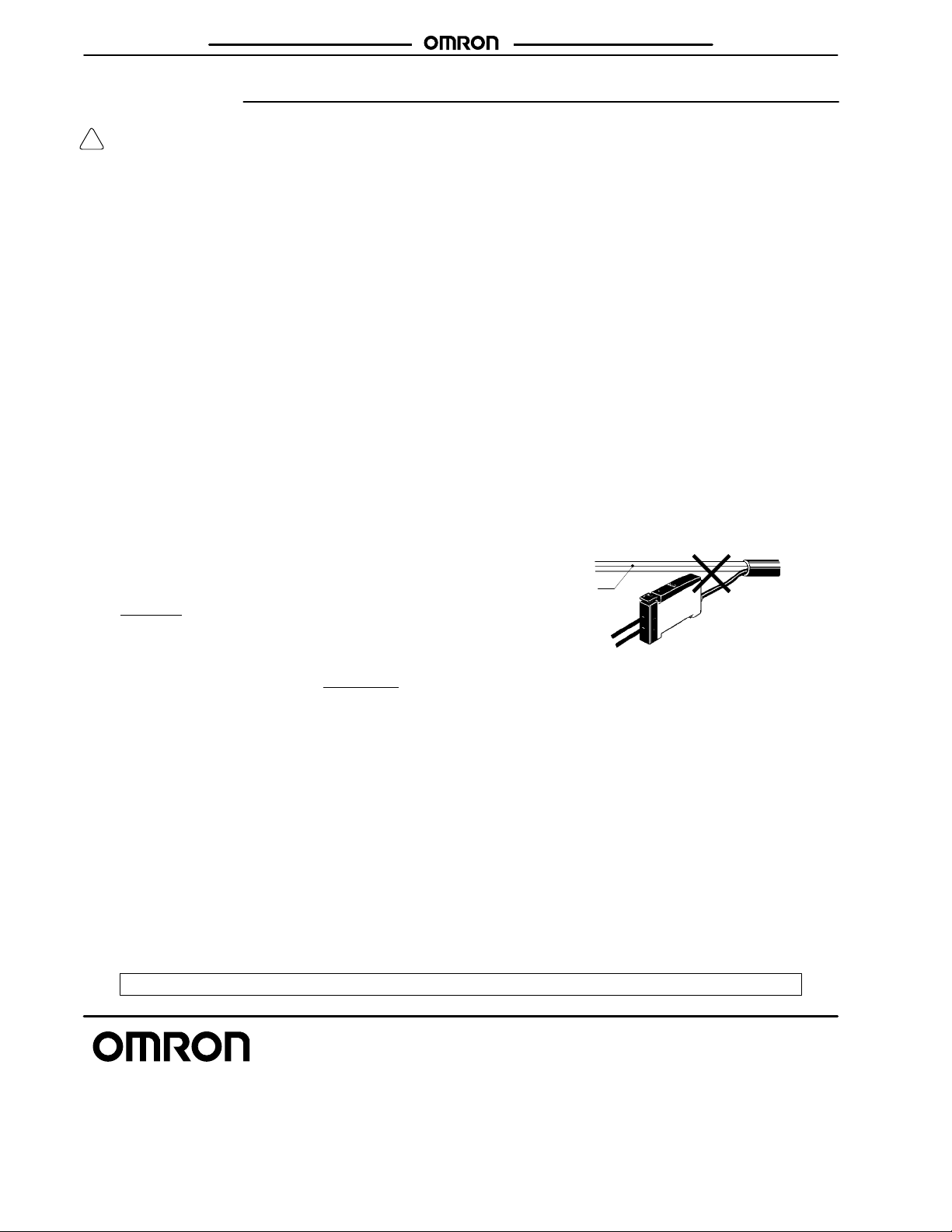
INSTALLING/WIRING
Do not wire the amplifier in the same conduit with power lines. Doing
so would cause induction between the lines, possibly resulting in
faulty operation or destruction. Always provide separate conduit for
the wiring to the amplifier.
Power line
Cat. No. CEDSAX3 10/99 Specifications subject to change without notice. Printed in U.S.A.
OMRON ELECTRONICS, INC.
One East Commerce Drive
Schaumburg, IL 60173
NOTE: DIMENSIONS SHOWN ARE IN MILLIMETERS. To convert millimeters to inches divide by 25.4.
1-800-55-OMRON
OMRON CANADA, INC.
885 Milner Avenue
Scarborough, Ontario M1B 5V8
416-286-6465