Alcons VR5 User manual

product manual
evolutionary audio solutions™

VR5 Product Manual. Rev. 1.0 3
1. Introduction
Dear customer,
Congratulations on your purchase of an Alcons Audio VR5 mini versatile monitor, and thank you for your condence in Alcons products.
We are very honoured to welcome you to the growing family of Alcons ambassadors!
The Alcons systems are handmade with pride in The Netherlands, combining the latest production techniques and technologies with dedication and
traditional craftsmanship.
Ever since its founding in 2002, the Alcons Audio team has been striving for the best possible sound reproduction for any type of source material and in any
size of application.To get the best performance out of your Alcons system, please read the precautions section in this manual before installing and operating.
We wish you many happy listening hours!
With best regards from the Alcons team,
Tom H. Back
Managing Director

VR5 Product Manual. Rev. 1.0 4
2. Product Description
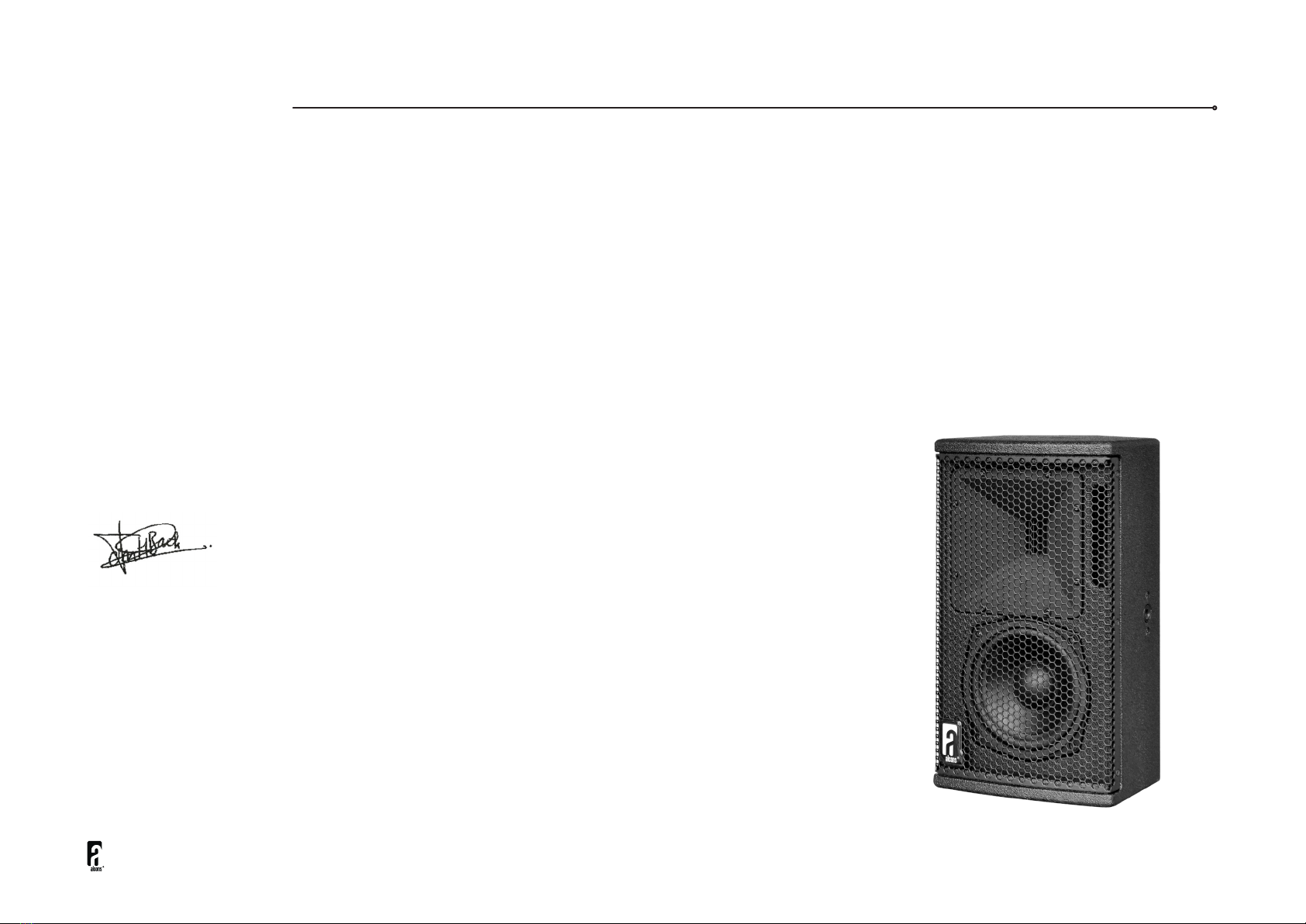
VR5 - mini versatile monitor
• RBN202 pro-ribbon HF driver with exceptional intelligibility and dynamic output
• Patented “Real-90” horizontal and “Real-60” vertical dispersion
• 1:1 non-compressed linear sound reproduction, with up to 90% less distortion
• SIS™ pre-wired for very high damping and further reduced distortion (with ALC
• Ultra-compact, multi-angle enclosure provides versatile deployment
• All Neodymium drivers for excellent performance-to-weight ratio
The VR5 is a 2-way mini versatile loudspeaker, specically designed for near-eld applications where ultimate delity response needs to be projected with wide
horizontal and vertical coverage.
The system brings the typical clear, dynamic and ultra-low distortion Alcons signature sound of the larger systems in a very small and unobtrusive package, for
both portable and permanent applications.
The VR5 consists of the RBN202 pro-ribbon driver for HF and a dedicated-designed 5” mid-bass with Active Coil™ for extremely low-distortion LF reproduction.
The VR5 HF section has a 500 W peak power input, enabling a 1:16 dynamic range with up to 90% less distortion from 1 kHz to beyond 20 kHz.
The patented (90-degrees) horizontal and (60-degrees) vertical dispersion of the revolvable waveguide, offers a wide and consistent coverage up to the highest
frequencies; Very important for the imaging in stereo or immersive systems.
Due to the “compression-less” principle of the pro-ribbon transducer technology, the system has a fully linear response at any SPL, for an intuitive 1:1
performance.
For full system performance, the VR5 needs to be driven by an ALC controller-amplier, delivering maximum sound quality with increased headroom and utmost
operation reliability and exibility.
The Signal Integrity Sensing™ pre-wiring ensures complete cable/connector compensation between the VR5 and ALC, signicantly increasing response accuracy,
regardless of cable length and system impedance, with tight and accurate mid and bass response as result.
The combination of the asymmetric multi-angle enclosure, the revolvable waveguide and the ACO™ color option provides for inconspicuous low prole stage,
stand, wall or ceiling positioning. The 5 M10 mounting points enable swivel bracket, shoulder eye bolt and mic stand deployment.
Typical (short to medium throw) applications for the VR5 range from reference monitor, low-prole stage-lip/front-ll, stage monitor, under-balcony system up to a
neareld main PA system, in combination with a separate subwoofer. The BF121 subwoofer is a perfect companion for the VR5 monitor as super-compact PA
system; It packs the same punch and accuracy as its bigger brothers BF151 and BF181 compact subwoofers.

VR5 Product Manual. Rev. 1.0 5
3. Precautions
Read this manual carefully before installing and operating your system. Retain this documentation for future reference.
1. Due to the extremely low distortion performance of the Alcons sound systems, the experienced sound pressure level is higher than it appears. Prolonged
exposure to high sound pressure levels can lead to hearing damage; Protective gear should always be available.
2. Work with qualied personnel for installing the system; Installation should only be carried out by qualied personnel who are familiar with the techniques,
procedures and safety recommendations stated in this manual.
3. Ensure health and safety during installation and operation; All persons must wear protective headgear and footwear at all times.
4. Check conformity of any conguration and respect the maximum allowed values and the safety level recommended by Alcons Audio outlined in this manual.
5. Verify that the Working Load Limit (WLL) of all mounting hardware and accessories is respected. Alcons Audio is not responsible for any equipment and
accessories provided by third party manufacturers.
6. Ensure that the surface is suitable for mounting a loudspeaker; Do not mount the loudspeaker assembly on unstable ground or surface. As a general rule,
Alcons Audio recommends the use of safety straps at all times.
7. Do not make connections with the loudspeaker to the amplier while it is switched on. Always shut off the amplier when making connections to it, and mute the
inputs when making connections to preceding equipment in the chain.
8. Do not operate the system in wet environments and protect it from excessive water or sun / UV exposure. The system has an IP43 rating and should be treated
accordingly.
9. Regularly check the loudspeaker for damage to the transducers, cabinet and mounting points, as this can severely compromise the system’s performance. Refer
10. Save the packing material. Should you ever need to ship the loudspeaker, use only the original packing.

VR5 Product Manual. Rev. 1.0 6
4. Connection
The VR5 is a passive-ltered loudspeaker and features a high quality crossover network. As such, the VR5 requires one processing/amplier channel for
amplication. To activate the Signal Integrity Sensing™ circuit in the amplied loudspeaker controller (ALC), the use of a 4-core loudspeaker cable with NL4
Speakon® connectors is required;
The two extra wires are used for voltage sensing at the loudspeaker terminals. The output+ and sense+ wires are connected together at the loudspeaker+
terminal, and the output- and sense- wires are connected together at the loudspeaker- terminal.
The Speakon®connector is wired as follows:
Speakon®male plug viewed from the wiring side
1+ Output+
1 - Ouput –
2+ Sense +
2 - Sense -

VR5 Product Manual. Rev. 1.0 7
4. Connection
If you do not want to use the SIS feature at all, the sense wires should be connected to the output wires at the amplier output in the Speakon® connector.
Warning!
Never connect the sense+ to the output- terminal or vice versa, or short circuit both sense wires! Since you are disabling the amplier’s feedback network, the
amplier can produce a large amount of DC at its output. Through its protection circuitry, the Sentinel will shut-off and will not pass any audio.
Loudspeaker connection without SIS™ Normal loudspeaker operation
Use bridge mode when you want to combine the power of amplier channel
1+2 or 3+4 into one loudspeaker load.
In bridge mode connect your loudspeaker with or without SIS to the channel 1
and channel 2 outputs (or channel 3 and 4) as shown above. Sentinel 3 only!

VR5 Product Manual. Rev. 1.0 8
4. Connection
For a given loudspeaker impedance, the proportional power loss as a function of cable length and cable gauge is given in the next table:
To calculate the SPL losses from these percentages in dB’s, the following equation may be used:
dB loss = 20 * log(1 – (%loss/100))
In the next table a few percentages are converted to dBs:
“The VR5 has a 16 ohms impedance which makes parallel connection possible of multiple cabinets.
It is technically possible to connect up to 8 VR5 cabinets on one amp channel, with a resulting impedance of 2 ohms; However, we recommend not going any
lower in impedance than 2.7 ohms, which is 6 VR5 cabinets in parallel, to provide ample power to each cabinet.”
8Ω4Ω
1.5 mm² 2.5 m² 4 mm² 6 mm² 1.5 mm² 2.5 m² 4 mm² 6 mm²
5 meters 1.4 % 0.8 % 0.5 % 0.4 % 2.8 % 1.7 % 1.1 % 0.7 %
10 meters 2.8 % 1.7 % 1.1 % 0.7 % 5.4 % 3.3 % 2.1 % 1.4 %
15 meters 4.1 % 2.5 % 1.6 % 1.1 % 7.8 % 4.9 % 3.1 % 2.1 %
20 meters 5.4 % 3.3 % 2.1 % 1.4 % 10.2 % 6.4 % 4.1 % 2.8 %
25 meters 6.6 % 4.1 % 2.6 % 1.7 % 12.4 % 7.8 % 5.0 % 3.4 %
30 meters 7.8 % 4.9 % 3.1 % 2.1 % 14.5 % 9.3 % 6.0 % 4.1 %
40 meters 10.2 % 6.4 % 4.1 % 2.8 % 18.5 % 12.0 % 7.8 % 5.4 %
50 meters 12.4 % 7.8 % 5.0 % 3.4 % 22.1 % 14.5 % 9.6 % 6.6 %
% loss dB loss
1 % 0.1 dB
2 % 0.2 dB
5 % 0.4 dB
10 % 0.9 dB
15 % 1.4 dB
20 % 1.9 dB
25 % 2.5 dB
30 % 3.1 dB
35 % 3.7 dB

VR5 Product Manual. Rev. 1.0 9
Fig 1. Select loudspeaker 1 > Select V-series
Fig 3. Select loudspeaker 1 > Conrm VR5, be aware
of possible audio interruptions
Fig 2. Select loudspeaker 1 > Select VR5
Fig 4. Select loudspeaker 2 >
Repeat the previous three steps for your 2nd loudspeaker
5. Installation
The VR5 is to be driven by the ALC controller-amplier for full system performance, delivering maximum sound quality with increased headroom and utmost
operation reliability and exibility.
The operation reliability is guaranteed by the advanced limiting algorithms in the DSP; The values of the dedicated preset are based on the VR5 system
surviving a 1000 hours durability test in the R&D test bunker at Alcons Audio HQ.
On the ALC, the correct VR5 preset needs to be selected. Go to the “Preset” tab; tap the button on the channel you wish to operate the VR5 with;
A selection box will appear with the different series groups.
(See g 1)
With the encoder select the “V-series”; then select “VR5”;
(See g 2)
A conrm box will appear.
(See g 3)
. Repeat these steps for your 2nd loudspeaker
(See g 4)

VR5 Product Manual. Rev. 1.0 10
Fig 5. Range selection
Select fullrange or HP at 80Hz or 100 Hz Fig 6. Low-pass ltering
Optional setting for low-pass ltering at 80 Hz or 100 Hz
Optional settings:
5. Installation
Now the VR5 is dedicated to this channel; Next you can make a choice of lter settings within the preset: 80Hz high-pass, 100Hz high-pass or full-range operation.
The Alcons VHIR™ processing ensures a at phase response down to 200Hz with minimal latency; This enables the user to select any Alcons subwoofer to
seamlessly work with the VR5, with optimized phase response.
Optional settings in combination with a subwoofer (BF121 in example): The VR5 preset can be set on high-pass ltering at 100Hz, depending on the requirement
(typically, the 100Hz setting is preferred in higher SPL applications).
To match the VR5 and obtain a at system response, the BF121 preset needs to be set on the same frequency preset, 80Hz or 100Hz.
(See g 5)
In applications where the VR5 is positioned further away from the subwoofer, the VR5 preset may be set on full-range, with the accompanying sub set on 80Hz.
(See g 6)

VR5 Product Manual. Rev. 1.0 11
Warning!
Always make sure the correct system preset has been selected, before unmuting / starting-up the system, as operating with incorrect settings can severely
damage the loudspeaker and voids warranty.
Fig 7. EQ
Frequency adjustment per channel Fig 8. Delay
Delay adjusting to t the environment
EQ and Delay settings:
5. Installation
The dedicated factory VR5 preset ensures a at frequency response; With the equalizer and delay sections in the ALC, the performance of the VR5 can be adjusted
to the environment and application.
(See g 7)
These settings can be stored in the on-board user-preset bank.

VR5 Product Manual. Rev. 1.0 12
6. Operation
The VR5 is equally suitable for mobile deployment as well as xed installation.
Due to the patented wide 90 x 60 degree HF dispersion, placement is less critical to still obtain a good audience coverage, both horizontally as well as vertically;
However, it is recommended to focus the VR5 with its horizontal and vertical axis to the audience, so as to have the best projection, while minimizing spill outside
the listening area.
60°
90°
90°
Constant horizontal directivity = consistent full
frequency audience coverage 60° vertical dispersion = wider sweetspot
and audience coverage in close-field applications

VR5 Product Manual. Rev. 1.0 13
6. Operation
The dual-angle cabinet makes for a low-prole in different positions in case of ceiling mounting or use as a oor monitor.
The VR5 is also available in mirror-version, as VR5M, This cabinet shape is ideal in critical monitoring applications, to have a symmetric left/right system
conguration. It also further expands the low-prole mounting options.
The 5 M10 mounting points enable the use of swivel brackets, shoulder eye bolt and microphone stand deployment to get the best positioning for the VR5.
Mounting option examples:
Standmount w. pan/tilt
BRKVR5 + STMT Standmount non pan/tilt
reducer ange 36mm to M10
thread (STMTM10)
Vertical mounting w. pan-only
BRKVR5HOR

VR5 Product Manual. Rev. 1.0 14
6. Operation
Mounting option examples:
Rear mounting w. pan/tilt
Multiple angles with Omnimount
15.0W
Top/ bottom mounting
Vertical mounting with
K&M 24185-317-55
Vertical mounting w. pan/tilt
BRKVR5HOR + K&M 24471 & 24358(AP5)

VR5 Product Manual. Rev. 1.0 15
6. Operation
Mounting option examples:
Truss clamp
Thread length
max. 20mm (0.8”)below clamp.
Horizontal mounting w. tilt only (ceiling)
BRKVR5HOR
Horizontal mounting w. tilt only (floor)
BRKVR5HOR

VR5 Product Manual. Rev. 1.0 16
7. Accessories & options
BRKVR5
The BRKVR5 is a swivel yoke for a single VR5 mini
monitor.
The yoke is connected to the cabinet with two M10
knob bolts on the side of the cabinet.
The bracket can be tted with an optional truss
clamp, TV-spigot or STMT stand-mount adapter,
with M10 (2) or M12 (1) bolt/nut connection.
The BRKVR5 is certied for a safety-rating of 10:1,
for one cabinet VR5.
BRKVR5HOR
The BRKVR5HOR is a bracket for mounting a
single VR5 monitor in horizontal position.
The yoke is connected to the cabinet with two
steel strips on the side of the cabinet, secured with
two M10 bolts each.
The bracket can be wall/ceiling mounted through
two 8mm/0.3-in holes; The bracket can be tted
with an optional truss clamp, TV-spigot or STMT
stand-mount adapter, with M10 (2) or M12 (1)
bolt/nut connection.The BRKVR5 is certied for a
safety-rating of 10:1, for one cabinet VR5.
Mounting options:

VR5 Product Manual. Rev. 1.0 17
7. Accessories & options
STMT
The STMT is a 36mm stand mount sleeve,
enabling all swivel yokes to be used on standard
tripod stands or mounting accessories with a
diameter of 35mm.
It can be mounted on all BRK brackets, prepared
for STMT, with two (2) M10 bolt/nut combinations.
Includes a small diameter grip knob.
Mounting options:
STMTM10
The STMTM10 is a 36mm stand mount sleeve,
enabling speakers to be used on standard tripod
stands or mounting accessories with a diameter of
35mm.
It can be directly mounted on the cabinet, with the
M10 thread connection. Includes a small diameter
grip knob.

VR5 Product Manual. Rev. 1.0 18
7. Accessories & options
Transport options:ACO™ Colour option:
FC2VR5
Flightcase for 2 pcs. VR5 + BRKVR5 brackets
Also available as:
FC4VR5
Flightcase for 4 pcs. VR5 + BRKVR5 brackets
ACO™ (
Architect Colour Option)
The VR5 can be nished in any of the 180+
colours from the European RAL™ colour scheme

VR5 Product Manual. Rev. 1.0 19
8. Specifications
VR5
Front
VR5
Rear (side)
VR5
Rear (side)
VR5
Top/bottom
VR5
Rear
VR5 product views

VR5 Product Manual. Rev. 1.0 20
8. Specifications
Technical specifications
Frequency response 67 Hz – 20.000 Hz (+/- 3 dB)
59 Hz - (+/- 10 dB)
Sensitivity nominal 98 dB (200 Hz - 10 kHz)
Nominal impedance 16 ohms
Recommended drive Sentinel3 min., max. 6 pcs. per channel
(2.7 ohms)
Nominal SPL peak 121 dB (Sentinel3 200 Hz - 10 kHz)
127 dB (Sentinel10 200 Hz - 10 kHz)
Dispersion H x V 90° x 60° or 60° x 90° (@ 20 kHz)
Physical specifications
System 2-way, full-range
Filtering passive
Driver LF 1x AMB5NDAIC-16 5” Neodymium, vented
Driver HF 1x RBN202rs 2” pro-ribbon driver
Connectors 2x Speakon NL4 input/link
Physical dimensions mm inches
Height 339 13.3
Width 191 7.5
Depth 205 8.0
Weight (approx.) 6 kg 13.2 lb
Warranty 6 years limited
Table of contents
Other Alcons Speakers manuals