Alcons LR28 User manual


Rigging manual LR28 Rev. 1.45
2
Table of contents _______________________________________________
1 Introduction______________________________________________________________________________________3
2 Important safety instructions and precautions _________________________________________________________4
3 Installation_______________________________________________________________________________________5
4 Rigging components ______________________________________________________________________________6
5 Array configurations _____________________________________________________________________________10
Cabinet connections
_________________________________________________________________________________ 10
GRD28 options
_____________________________________________________________________________________ 12
GRD28B options
____________________________________________________________________________________ 13
GRD28 hoist options
_________________________________________________________________________________ 14
GRD28B hoist options
________________________________________________________________________________ 15
Fly mode array assembling and hoisting ____________________________________________________________________________________
16
Compression style array assembling and hoisting ____________________________________________________________________________
18
6 Service and support______________________________________________________________________________23
7 CE declaration of conformity_______________________________________________________________________25

Rigging manual LR28 Rev. 1.45
3
1. Introduction__________________________________________________
Dear customer,
Congratulations on your purchase of an Alcons Audio LR28 line array loudspeaker and thank you for your confidence in Alcons products. We are very honoured
to welcome you to the growing family of Alcons ambassadors!
For your safety, please read the Important safety instructions and the precautions section before rigging a loudspeaker array.
General features
The LR28 has the following features:
A unique seamless arrayability up to/beyond 20kHz.
Symmetrical 80°/110° dispersion in the non-coupling plane.
Ultra-high-performance line-array system for even the largest applications.
Non-compressed 1:1 HiFi-quality sound reproduction.
Intuitive predictable linear response behavior and identical tonal balance at any SPL.
14” pro-ribbon HF section with exceptional intelligibility and “throw”.
Maximum dynamic headroom reserve with up to 90% less distortion.
Fully coherent and symmetric pattern control in horizontal and vertical plane.
SIS™ pre-wired for very high system damping and further reduced distortion.
All Neodymium drivers for excellent performance-to-weight ratio.
LR28 rigging features
The trapezoidal cabinet is fitted with integrated mounting hardware, enabling angle-setting on the cabinets, without lifting the array, resulting in safer and faster
set-up with minimal handling. The rigging system supports different modes of array assembling and has a working load limit of 24x LR28, 32x LB28 or 16x
LR28B cabinets under 10:1 safety.
Manual
This manual is written in a compact and easy readable way. You can contact Alcons Audio for more in-depth information on different items or situations

Rigging manual LR28 Rev. 1.45
4
2. Important safety instructions and precautions _____________________
Read this manual
1. Follow all safety instructions as well as the warning messages.
2. Never incorporate equipment or accessories not approved by Alcons Audio.
3. Read all the related product information before using the system.
4. Work with qualified personnel for rigging the system.
5. Installation should only be carried out by qualified personnel who are familiar with the rigging techniques and safety recommendations stated in this
manual.
6. Ensure health and safety during installation and setup.
7. All persons must wear protective headgear and footwear at all times. Under no circumstances personnel is allowed to climb into a loudspeaker assembly.
8. Respect the Working Load Limit (WLL) of third party equipment.
9. Alcons Audio is not responsible for any rigging equipment and accessories provided by third party manufacturers. Verify that the Working Load Limit
(WLL) of the suspension points, chain hoists and all additional hardware rigging accessories is respected.
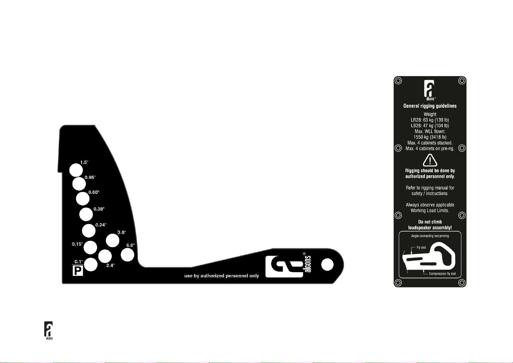
10. Respect the maximum configurations and the recommended safety level.
11. For safety issue, respect the maximum configurations outlined in this manual. To check the conformity of any configuration in regards with the safety level
recommended by Alcons Audio.
12. Be cautious when flying a loudspeaker array. Always verify that no one is standing underneath the loudspeaker array when it is being raised or lowered.
As the array is being raised, check each individual element to make sure that it is securely fastened to the adjacent element.
13. Never leave the array unattended during the installation process. As a general rule Alcons Audio recommends the use of safety slings at all times.
14. Ensure that the surface is suitable for ground-stacking a loudspeaker array.
15. Do not stack the loudspeaker array on unstable ground or surface. If the array is stacked on a structure, platform, or stage,
always check that the latter can support the total weight of the array. As a general rule, Alcons Audio recommends the use of safety straps at all times.
16. When a loudspeaker assembly is deployed in an open air environment, wind can produce dynamic stress to the rigging components and suspension
points. If the wind force exceeds 6 Beaufort scale, lower down and/or secure the loudspeaker array.
The exclamation point within a triangle is intended to alert the user to the presence of important operating
instructions in the literature accompanying the product.

Rigging manual LR28 Rev. 1.45
5
3. Installation___________________________________________________
Unpacking
Carefully open the shipping carton and inspect all the parts. Every Alcons product is thoroughly tested and inspected before leaving the factory and should arrive
in perfect condition. If you find any damage, notify the shipping company immediately. Only you, the consignee, may initiate a claim for shipping damage. Be
sure to save all packing materials for the carrier’s inspection.

Rigging manual LR28 Rev. 1.45
6
4. Rigging components __________________________________________
LR28 loudspeaker
1) LR28/ LB28 cabinet LR28/80° cabinet (drawn)
2) Front coupler Coupler, lockable with quick release pin
3) Bar handle Handles in the cabinet ensure easy handling
4) Pin pre-rig transport Pin holding the cabinet at 0° on the PRRGL28
5) Signal input/ link Input/ link for the audio signal
6) Angle frame This frame holds features for the angle setting and back coupling
7) Pin slider Black color indicates LR28/80°, green LR28/110°
2
1
7
3
6
5
4

Rigging manual LR28 Rev. 1.45
7
4. Rigging components __________________________________________
LR28B loudspeaker
1) LR28B cabinet LR28B cabinet
2) Coupler Rotatable couplers, lockable with quick release pin
3) Bar handles Handles in the cabinet ensure easy handling
4) Bottom connector Connection with two holes, enabling a 2,5° splay angle
1
2
4
3

Rigging manual LR28 Rev. 1.45
8
4. Rigging components __________________________________________
GRD28
This grid is used to suspend a vertical cabinet array. It features a sliding
extender bar and an adjustable foot for stacking. It has a mounting position and
through hole for the Teqsas laser/ inclinometer. It has a WLL of 24x LR28, or
32x LB28 cabinets. all points measure 20mm/0.8-in. It is recommended to use
3,25T shackles in any situation and always use two hoists
GRD28B
The GRD28B enables the LR28 line-array modules, the LB28 line-array
extension modules, LR24 line-array modules and LR28B line-array bass
modules to be flown and ground stacked. The grid can be suspended from
multiple hoist options on top of the grid (all points 20mm/0.8-in for 3,25T
shackles).
CNVB1828
This bracket is a transition frame to suspend a small LR18 array under a LR28 for down fill
applications. It enables a maximum tilt angle of 8° between LR28 and LR18. CNVB1828 is
certified for six (6) cabinets LR18.

Rigging manual LR28 Rev. 1.45
9
4. Rigging components __________________________________________
PRRGL28
This wheeled Pre-rig frame is used to transport 4 LR28 or LB28 cabinets. It can
also be used as a ground stack base, with optional adjustable SWFTPRRGL28
feet . It has a 0° or 6° angle arm. The frames can be stored on top of each other,
using the wheel recesses. The SFTCVR4LR28 soft cover is an essential option
for the LR28 Pre-rig.
PRRGLR28B
This wheeled Pre-rig frame is used to transport up to 3 LR28B. An optional soft
cover is an essential option for the LR28B Pre-rig.
WLFRML28
This frame is used as a pull-back device for compression style flying. The hoist point measures
20mm/0.8-in for a 3,25T shackle. The wheels are detachable. It also ensures, with the wheels
mounted, that the bottom cabinet does not get damaged during the optional caterpillar style hoisting.

Rigging manual LR28 Rev. 1.45
10
5. Array configurations___________________________________________
Cabinet connections LR28
Array assembling can be done using two fly options. This is determined by the available space, time or available parts.
There are 10 user selectable logarithmic angles, which can be determined by the Alcons Ribbon Calculator™ simulation
program. The angles are suitable for both caterpillar and compression style array flying.
The angle lay-out is pictured below. The “P” indicates the position of the angle pin, when parking the angle arm. This is done
in case of single LR28 cabinet transportation. The general rigging guidelines on the right is also shown at the back of the
cabinet.

Rigging manual LR28 Rev. 1.45
11
5. Array configurations___________________________________________
Cabinet connections LR28B
LR28B has rotatable couplers, secured/ parked with a quick release pin. This pin is also
used to make the connection to the GRD28B or the adjacent cabinet.
It is also possible to use the LR28B as a single standing subwoofer. It then stands on its long
or short side with slider feet.
At the lower end of each bracket, there are two holes, which determines the splay angle 0°
or 2.5°. This selection is be made before hoisting. Only the front facing side needs to be
selected. The back side is set at 0°.
LR28B can be flown in a cardioid setup, using this method. There is a second NL4
Speakon connector mounted in the front grill.
It is advised to use a separate cable hang for the speaker cables, as the NL4 (front +
rear) Speakon connectors cannot take the entire cable weight.
A second GRD28B, under an LR28B (to enable the connection to an LR28 or LR24
array) is connected with its top rotatable couplers to the 0° holes on the LR28B cabinet. This
is also the setup for ground stacking LR28B+LR28/ LR24.
Connection indication GRD28B

Rigging manual LR28 Rev. 1.45
12
5. Array configurations___________________________________________
GRD28 options
The GRD28 has multiple mounting options. The picture on the right shows the different
pick-points for flying an array. Use 3,25T shackles in any situation. The A1 & A6/ A7
marked points are the default hoist points.
It is also possible to use one pick point from the A5 pattern. Use it only for max. 12x LR28
cabinets.
Use 2 hoists at all times.
In case of permanent installation, combine points A2 and A6 to create a stable 3-point
hang.
A3 indicates the mounting position of an angle inclinometer. It has a 4xø4mm;
16.5mm x 108.8mm hole pattern for the Teqsas laser/ inclinometer.
Always use both A4 pins when adjusting the extender bar pick-point A7. The extender bar
can also be mounted at the front.
The FCGRD28 flightcase is available as a transport option.
The picture on the left shows the GRD28 in the stacked position. This is used when the
PRRGL28 Pre-rig is not suitable. Ensure that there is a stable and flat surface on which
to build the stacked array. A max. of 4 cabinets can be stacked in this way. Take off the
adjustable foot frame and attach it on the extender bar. Lock it with both small pins. The
front of the stacked array will rest on the front A8 stands. The back can be extended
and height-adjusted. Assemble the array of 4 cabinets and use the compression fly slot
on the angle arm, when adjusting the angles.

Rigging manual LR28 Rev. 1.45
13
5. Array configurations___________________________________________
GRD28B options
The GRD28B has multiple mounting options. The
picture on the left shows the different pick-points for
flying an array. The grid is used on LR28B in the
shown orientation. The A1 & A2 marked points are the
default hoist points.
L1 marks the front connection points to a LR28
cabinet. L2 are the LR24 connection points. In both
situations, the GRD28B needs to be 180° turned
The 3 holes A5 will hold the connection pin between
the LR28 or LR24 angle arm and GRD28B
Use 3,25T shackles at all times
A3 indicates the mounting position of an angle
inclinometer. It has a 4x ø4mm; 16.5mm x 108.8mm
hole pattern for the Teqsas laser/ inclinometer.
A8 marks the adapter angle arms in their transport
position. They can connect to the bottom connection
points on the LR28B and shall pinned by G1 on the
GRD28B. The G2 pins connect to the bottom coupling
of a LR28B.
As stated before, the GRD28B needs to be turned
180° to act as the connection between LR28B and
LR28/ LR24

Rigging manual LR28 Rev. 1.45
14
5. Array configurations___________________________________________
GRD28 hoist options
The schematic picture below shows the possible array hang options A-D in fly mode and stack arrangement E&F
As stated earlier, the array angles can be determined through the Alcons Ribbon Calculator™ simulation program. The Centre of Gravity needs to be between
the outermost pickpoints at all times!
When stacking (E&F), ensure that the centre of gravity is well within the PRRGL28/ GRD28 support points.
The picture below shows the dimensions of the GRD28 at the different extendable positions of the GRD28EXTBR extender bar.

Rigging manual LR28 Rev. 1.45
15
5. Array configurations___________________________________________
GRD28B hoist options
The schematic picture below shows the possible array hang options m-p and stack arrangement q & r with LR28B and LR28/ LR24.
Note the chain setup on the back of the array, when flying LR28/ LR24 in compression mode.
Attaching LR28/ LR24 to LR28B (flying or stacking) requires a second GRD28B (o). This is due to the fact that the LR28/ LR24 have 3 pick points and LR28B is
a 4 pick points set-up. LR28B can therefore be mounted 180° to the adjacent LR18B cabinet, creating a cardioid setup (m). Always attach each pick-point on
GRD28B with 2 pins to the top couplers of the LR28B

Rigging manual LR28 Rev. 1.45
16
5. Array configurations___________________________________________
Fly mode array assembling and hoisting
Using this mode the LR28 rigging system uses the vertical PRRGL28 pre-rig transporter combined with (non-compression) vertical fly array hanging. This mode
uses the top “fly slot” in the angle arm and is best suitable for large 12->24 pcs arrays
The schematic drawing shows the building steps G->L with 2 chain hoists.

Rigging manual LR28 Rev. 1.45
17
5. Array configurations___________________________________________
Fly mode array assembling and hoisting
The numbers in the picture, correspond with the LR28 rigging
components overview pictured earlier.
This flying option uses the PRRGL28 pre-rig transport option. The
PRRGL28 (E) transports 4x LR28 or LB28 cabinets in a vertical
position. Take off the protective SFTCVR4LR28
Start with the first 4 cabinets. (G). This is a two man job
Hold each cabinet and remove the angle pin (6) and red buttoned pin
(12). Let it rest onto the lower cabinet. Work your way down.
Attach the GRD28 and make the angles using the top “fly” slot in the
angle arm, with the angle pin (6). Place the red pin (12) in the rubber
lined transport hole. Attach GRD28 to the top cabinet. Hoist the first
piece of the array. It will stretch out to the correct cabinet angles.
When the first array piece is still at working height, speaker cabling
can be attached using a hoist sling to the extender bar, to take the
cable weight away from the array.
Place the next PRRGL28 under the suspended array (H). Make the
connection using the front couplers (2) and angle arm (8).
Hoist the 8 piece array (I). Remove the red 0° pins (12) and angle
pins (6) from the bottom 4 cabinets. Lower the whole array down and
pull it backwards (J). The lower cabinets will compress against each
other.
The angles can now be set using the angle pins (6) and the top “fly”
slot .
Hoist the array. The array will stretch out to the desired angles.
detach the PRRGL28 from the array (K).
Angle out the array using the back/ front chain hoists (L).
Landing the array
Attach the PRRGL28 pre-rig to the bottom cabinet with the small
angle arm at 0°. This is a two man job. Land the array and pull the PRRGL28 backwards. The cabinets will start to compress against each other. This will take
of the weight of the angle pins (6). Pull the angle pins (6) of the bottom 4 cabinets. Hoist the array back up. The 4 cabinets will stretch out to 0°. Put the red pins
(12) into their 0° holes and lower the PRRGL28 onto the ground. Detach the top 4
th
cabinet on the PRRGL28 from the array. Repeat this for the remaining array
pieces.

Rigging manual LR28 Rev. 1.45
18
5. Array configurations___________________________________________
Compression style array assembling and hoisting
This procedure is also used when a LR28B section is used in the array under GRD28B
This flying option is best suited for small 2->12 pcs arrays. The red buttoned pin (12) is crucial in this situation. It
ensures that the cabinets (1) will stay in a 0° position. The angle arm can be adjusted while this pin is in position or “0°
hole”.
Take the top cabinet angle arm out of the transport position and put the red pin (12) in.
Choose the angles by aligning the angle pin (6) with the bottom compression fly slot in the angle arm (8).
The angle setting can be done at the warehouse or on-site. There will be substantial pressure on the red pin (12) when
adjusting the angle arm (8).
A slight push/ tilt against the overlying cabinet will also help to ease this pressure. The angle frame (10) has special hardened frame to
guide the pin.
When the first cabinets are ready, attach GRD28 to the top cabinet. Ensure that it has the extender bar (B) mounted at the preferred
extension. Always use the 2 pins (A4) for each extender bar position
Use a hoist sling to take the weight of the speaker cables away from the cabinet array.
Attach a manual 0,75T lever hoist, with overload protection, from the bottom shackle position on the extender bar. Be sure to have
sufficient chain length. Use an extra safety chain in combination with the lever hoist. It is not allowed to use a motor hoist.
Take the PRRGL28 (E) off when the first 4 piece LR28 array is suspended. This is a two man job.
Remove all the red buttoned 0° pins (12) and place them in the rubber lined parking holes (13)
Position the next PRRGL28 under the suspended array. Ensure that the angle adjustments are done.
Lower the suspended array to make the three point connection (front couplers + angle arm coupling). You can remove the top red 0° pin
to make the back connection easier. When finished and the combined array is suspended in the air, pull out the red buttoned pins (12).
Continue this procedure until full array length is reached.
End with attaching the WLFRML28 (C) under the lowest cabinet. Slide the cabinet connecting pin (7) to the open position. Then hook the
frame onto the front couplers (2) and lock with the pins. Now make the connection with the cabinet connecting pin (7) and lock it.

Rigging manual LR28 Rev. 1.45
19
5. Array configurations___________________________________________
Compression style array assembling and hoisting
Start hoisting the (lever) hoist to make the cabinet angles. This has to be done by an authorised person. Stop when there is no more slack in the array. This
can be checked by pushing the array back and forth and listening for any slack noises in the angle setting frames.
Do not over-compress the array, as this can cause damage to the suspension system !
After the compression stage, the angle of the entire array can now be adjusted. Use an angle inclinometer on the GRD28.
The following schematic drawing shows the three hoisting stages with a 4 pcs array.
1) After array building
2) Compression to reach the desired angles
3) Array angling

Rigging manual LR28 Rev. 1.45
20
5. Array configurations___________________________________________
Compression style array assembling and hoisting
The schematic picture below shows compression style array hoisting, using two separate chain hoists. This set-up can be done with a max. of 12 cabinets. The
first motor hoist is connected to the hole nr. 5 (pattern A5) in the centre of gravity. The second hoist chain has to be attached to the WLFRML28 (C). In this
way, the angles can be set using compression and the entire array can be angled.
4) After array building
5) Compression to reach the desired angles
6) Array angling
Other manuals for LR28
1
This manual suits for next models
2
Table of contents
Other Alcons Speakers manuals