Alemite 323440-4 User manual

323440-4
323440-A1
323440-C1
323440-D1
323440-E1
Service Guide
SER 323440-4
Alemite, LLC
167 Roweland Avenue, Johnson City, Tennessee 37601
www.alemite.com
Copyright © 2005 by Alemite, LLC
This document contains confidential information that is the property of Alemite, LLC
397871 and is not to be copied, used, or disclosed to others without express written permission. Revision (7-05)
Description
The air motors in the 323440 series power a
variety or fluid and material pumps. The pump tubes
that connect to these motors can be either divorced or
of a non-divorced design.
Divorced and Non-Divorced
Overview
Pumps that disassemble into separate air motor
and pump tube entities are considered divorced.
These assemblies connect via a coupling arrangement
that is open to atmosphere. The material outlet on
divorced pumps is on the pump tube.
Non-divorced pumps contain a body (shown in
phantom in Figure 2) that fits directly into the base of
the motor. This body allows material distribution
(with the use of an adapter) through an access hole in
the air motor. See Figure 1.
Separation of this design requires the pump tube
to be unthreaded from the motor’s rod.
Air Motor 323440-A1 (Divorced Design)
This air motor can be purchased separately. It
contains the hardware necessary for pump tube
attachment. See Figure 1.
Air Motors for Non-Divorced Design
The air motors connected with pump tubes in a
non-divorced design are the remaining models. See
chart in Figure 1for comparison. These air motors
are available as an assembly with the pump tube.
Air Motor
Air Motor
Model
Pump Design Air Motor Base Rod
Divorced Non-
Divorced w/ Weep
Hole w/o Weep
Hole w/ Acme
Thread Stepped
323440-4
323440-A1
323440-C1
323440-D1
323440-E1 *
* With BSPP Air Inlet Body Adapter (See Table 1)
Air Motor Model Piston Dia. x Stroke Air Inlet Material Outlet Adapter Maximum
Air
Pressure
in. cm Body Adapter
323440-4, A1 -C1 and -D1 4-1/4 x 4 10.8 x 10.2 3/4" NPTF Not Applicable Available with Pump Only
(Divorced and Non-Divorced) **
323440-E1 3/4" BSPP (f) x 3/4" NPTF (m)
** For information on the maximum air pressure for the air motor, please refer to the pump’s Service Guide.
Table 1 Air Motor Model 323440 Series Specifications
Figure 1 Air Motor Model 323440 Series
Model 323440-A1 Shown

SER 323440-4 Air Motor
Revision (7-05) 2 Alemite, LLC
Figure 2 Air Motor Model 323440 Series - Exploded View

Air Motor SER 323440-4
Alemite, LLC 3 Revision (7-05)
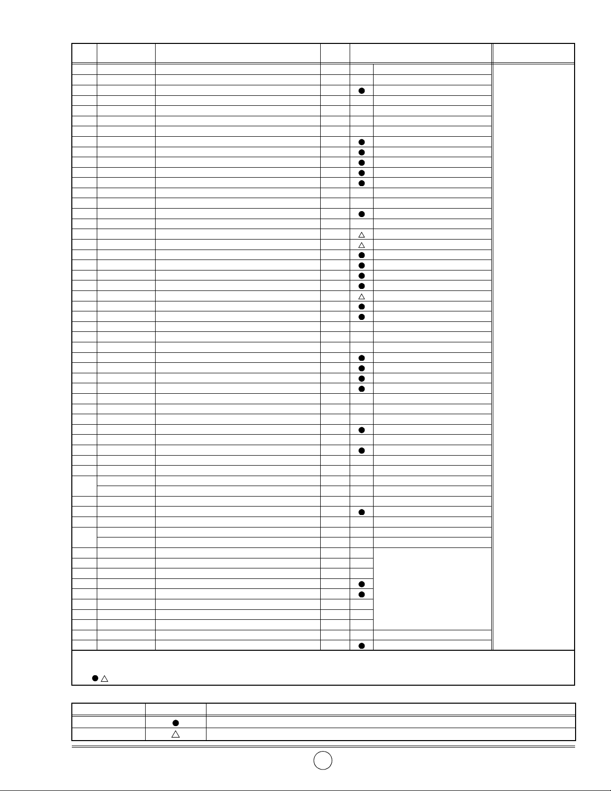
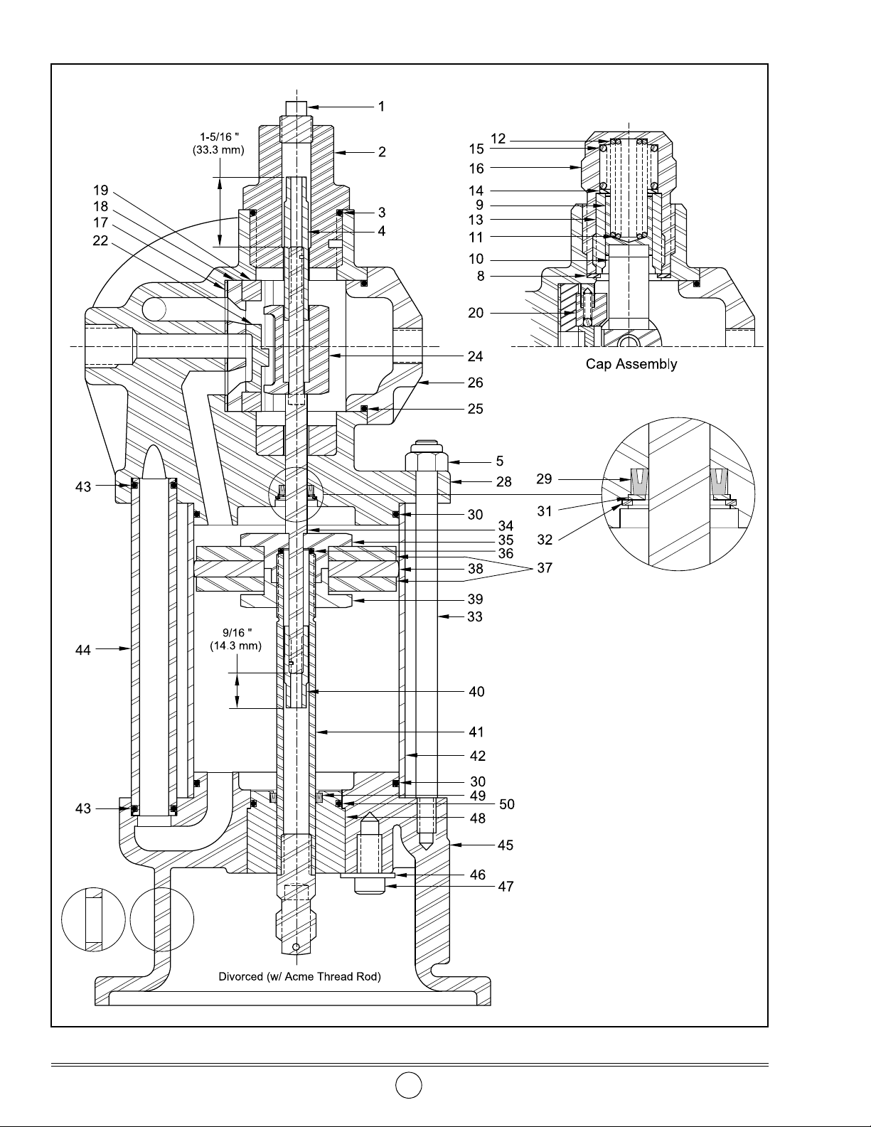
Item
No. Part No. Description Qty Notes Numeric Order
Part # (Item #)
1 48925 Plug, Pipe, 3/8 " NPT 1 11828 (53)
2 324076 Plug,1-3/4 " -12 (m) x 3/8 " NPT (f) 1 14546 (46)
3 171009-29 O-Ring, 1-9/16 " ID x 1-3/4 " OD 1 48925 (1)
4 324432 Nut, Upper Trip Rod, 3-3/8 " Long 1 77807 (51)
5 171130 Nut, Elastic Stop, 1/2 " -20 5 171000-12 (43)
6 323487 Setscrew, 5/16 " -18 x 1/2 " 2 171003-20 (30)
7 Plug, Socket Pipe, 3/8 " NPT 1 171006-15 (32)
8 323482 Gasket, 1.646 " OD (Copper) 2 171009-4 (36)
9 323450 Plunger 2 171009-29 (3)
10 323464 Toggle 2 171009-33 (50)
11 326738 Spring, 2.44 " Long 2 Model 323440-4, -A1 171009-35 (a)
12 323486 Spring, 3.00 " Long 2 171009-47 25)
13 323481 Cylinder, 1-5/16 " -20 2 171130 (5)
14 323484 Washer, 0.7 " ID 2 172013 (22)
15 323485 Spring, 1-5/16 " Long 2 172207-4 (52)
16 323483 Cap 2 311738 (7)
17 323468 Gasket, 2-13/16 " OD (Rubber) 1 314632 (49)
18 Seat, Valve 1 323443 (27)
19 323469 Stop 2 323444-2 (44)
20 323830 Guide, Valve 2 323466-4 (26)
21 Lockwasher, 5/16 " 4 323450 (9)
22 Screw, Cap, 5/16 " -18 x 1 " 4 323451-3 (41)
23 Slide, Valve 1 323459-2 (33)
24 323473 Shuttle 1 323460 (39)
25 171009-47 O-Ring, 2-11/16 " ID x 2-7/8 " OD 1 323461 (37)
26 323466-4 Body, Inlet, 3/4 " NPTF (f) 1 323462 (38)
27 323443 Screw, Cap, 3/8 " -16 x 7/8 " 4 323464 (10)
28 333203-D1 Head Assembly, Casting 1 323467 (18)
29 324290 V-Packing 1 323468 (17)
30 171003-20 O-Ring, 4 " ID x 4-1/4 " OD 2 323469 (19)
31 323474 Washer, 0.52 " ID 1 323470 (23)
32 171006-15 Ring, Retaining, 7/8 " Diameter 1 323473 (24)
33 323459-2 Rod, Tie, 1/2 " -13 x 1/2 " -20 5 323474 (31)
34 326471-1 Rod, Trip 1 323477-2 (42)
35 323478 Retainer, Piston 1 323478 (35)
36 171009-4 O-Ring, 5/8 " ID x 3/4 " OD 1 323479 (40)
37 323461 Washer 2 323481 (13)
38 323462 Packing 1 323482 (8)
39 323460 Nut, Piston, 13/16 " -20 1 323483 (16)
40 323479 Nut, Lower Trip Rod, 1-5/8 " Long 1 323484 (14)
41 323451-3 Rod, Piston 1 Model 323440-4, -A1, -C1, E1 323485 (15)
338833 Rod, Piston 1 Model 323440-D1 323486 (12)
42 323477-2 Cylinder 1 323487 (6)
43 171000-12 O-Ring, 5/8 " ID x 13/16 " OD 2 323488-5 (45)
44 323444-2 Tube 1 323493-B4 (45)
45 323493-B4 Base, Air Motor (w/ weep hole plug) 1 Model 323440-4, -A1, E1 323550 (48)
323488-5 Base, Air Motor (w/o weep hole plug) 1 Model 323440-C1, -D1 323551 (47)
46 Washer, 1/2 " 3
Model 323440-A1
323830 (20)
47 Screw, 1/2 " -13 x 7/8 " 3 324076 (2)
48 323550 Retainer, Packing (Brass) 1 324290 (29)
49 314632 V-Packing 1 324432 (4)
50 171009-33 O-Ring, 1-13/16 " ID x 2 " OD 1 326471-1 (34)
51 Nut, 1/2 " -20 4 326738 (11)
52 Lockwasher, 1/2 " 4 333203-D1 (28)
53 Screw, Cap, 1/2 " -20 x 2 " 4 338833 (41)
54 340122 Adapter, 3/4 " BSPP (f) x 3/4 " NPTF (m) 1 Model 323440-E1 340122 (54)
a 171009-35 O-Ring, 1-15/16 " ID x 2-18 " OD 1 Model 323440-4, -C1 384232 (21)
Legend:
Part numbers left blank (or in italics) are not available separately
designates a repair kit item
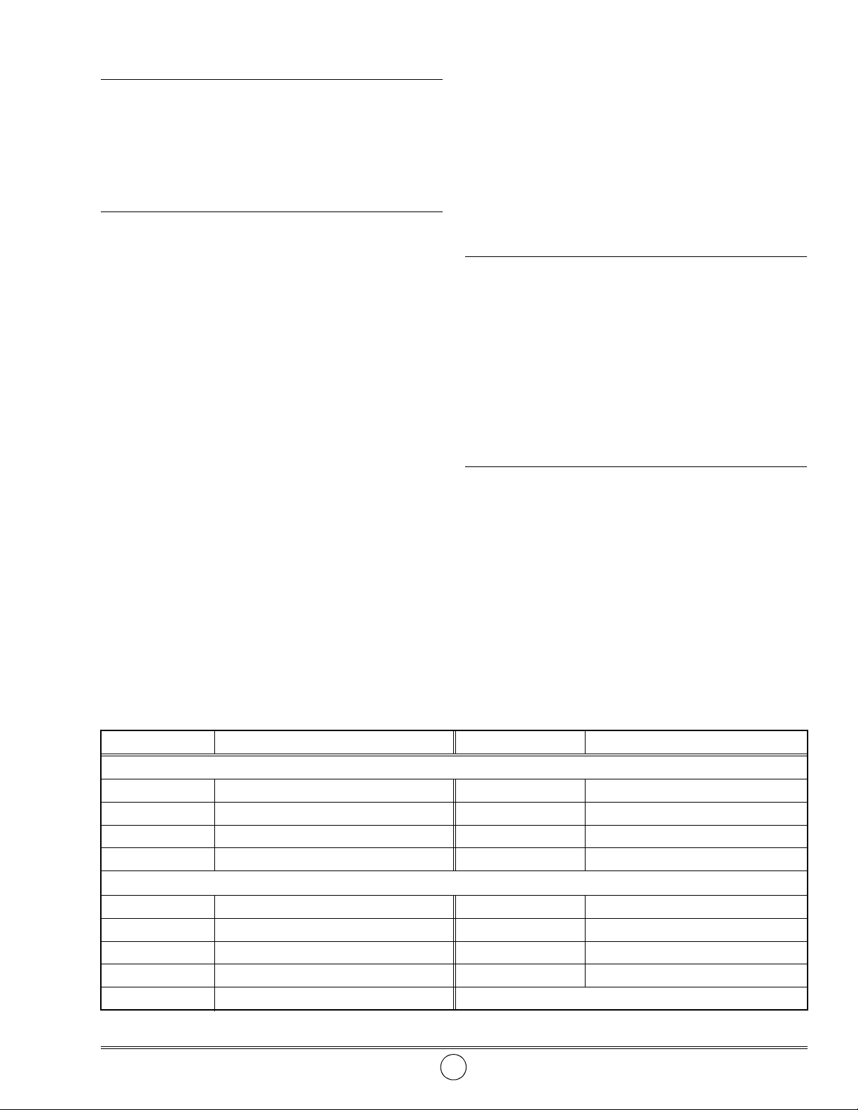
Repair Kits
Part No. Kit Symbol Description
398978-4 Kit, Major Repair (Includes Tube of 394009 Loctite 242 and 398030 Viscous H Lubricant)
398989 Kit, Slide Valve, Seat, and Gasket

SER 323440-4 Air Motor
Revision (7-05) 4 Alemite, LLC

Air Motor SER 323440-4
Alemite, LLC 5 Revision (7-05)
Overhaul
IMPORTANT: Prior to performing any
maintenance procedure, the following safety
precautions must be observed. Personal
injury may occur.
WARNING
Do not use halogenated hydrocarbon sol-
vents such as methylene chloride or 1,1,1-trichlor-
ethane in this motor. An explosion can result
within an enclosed device capable of containing
pressure when aluminum and/or zinc-plated parts
come in contact with halogenated hydrocarbon
solvents.
Release all pressure within the system prior to
performing any overhaul procedure.
• Disconnect the air supply line from the motor.
• Into an appropriate container, operate the
pump’s control valve to discharge remaining
pressure within the system.
Never point a control valve at any portion of your
body or another person. Accidental discharge of
pressure and/or material can result in injury.
Read each step of the instructions carefully. Make
sure a proper understanding is achieved before
proceeding.
NOTE: Refer to Figure 2 for component
identification on all overhaul procedures.
Disassembly
Separate Pump from Motor (Non-Divorced)
1. Clamp the Air Motor vertically in a soft-jaw vise.
2. Loosen the Jam Nut that secures the Pump Tube
assembly to the Air Motor assembly.
CAUTION
Support the Pump Tube assembly during removal.
Damage to components can occur.
3. Unscrew the Pump Tube [with attached components]
from the Air Motor.
4. Pull on the Pump Tube to expose the Coupling.
5. Remove the upper Spring Clip that secures the air
motor Piston Rod to the Coupling.
Accessories
Accessory items applicable to the these motors are
illustrated in Figure 3.
Item No. Part No. Description
1 324170 Muffler, 3/4 " NPTF (m)
2 323842 Eye Bolt, 3/8 " NPTF (m)
Figure 3 Air Motor Model 323440 Series Accessories

SER 323440-4 Air Motor
Revision (7-05) 6 Alemite, LLC
6. Unscrew the Coupling from the air motor Piston Rod.
• Rotate the entire Pump Tube assembly.
NOTE: For disassembly procedures of the
components in Air Motor Base (45), refer to
the Pump SER Service Guide for details.
Separate Motor from Pump (Divorced)
7. With the pump in a soft-jaw vise, remove Screws (53),
Lockwashers (52), and Nuts (51) that secure the Pump
to the Air Motor Housing.
8. Remove the Spring Clip that secures the air motor
Piston Rod to the Coupling.
9. Unscrew the Coupling from the air motor Piston Rod.
• Rotate the entire Air Motor assembly.
Air Motor
Head Assembly
10. Place the Air Motor vertically in a soft-jaw vise.
11. Unscrew Plug (2) from Head Assembly (28).
• Remove O-Ring (3) from the Plug.
12. Remove Plug (1) from Plug (2) as necessary.
13. Remove Screws (27) that secure Inlet Body (26) to the
Head Assembly.
• Remove the Inlet Body from the Head Assembly.
14. Remove O-Ring (25) from the Inlet Body.
15. Loosen Setscrews (6) that secure Caps (16) to the Head
Assembly.
• Unscrew each Cap from the Head Assembly.
16. Remove Springs (11) and (12) from each Cap.
17. Remove Gaskets (8) from the Head Assembly.
18. Lift Shuttle (24) upward and hold Trip Rod (34) with
an open-end wrench.
NOTE: Early model Trip Rods did not con-
tain a flat. Use a 5/32 " allen wrench to pre-
vent rotation of the Rod. See Figure 2.
19. Unscrew Nut (4) from the Trip Rod.
20. Unscrew Nuts (5) from Tie Rods (33).
• Remove the Head Assembly from the Tie Rods
21. Place the Head Assembly assembly on a flat surface.
22. Remove O-Ring (30) from the Head Assembly.
23. Remove the Shuttle, Toggles (10), Plungers (9), and
Slide Valve (23) from the Head Assembly.
24. Remove Screws (22) and Lockwashers (21) that secure
Valve Guides (20), Stops (19), and Valve Seat (18) to
the Head Assembly.
• Remove the Valve Guides and Stops.
IMPORTANT: Remove the Valve Seat
squarely from the Head Assembly. Should the
Valve Seat cock during removal, realign and
start again.
25. Remove the Valve Seat from the Head Assembly.
26. Remove Gasket (17) from the Head Assembly.
27. Remove Retaining Ring (32) that secures Washer (31)
and V-Packing (29) in the Head Assembly.
• Remove the Washer and the V-Packing.
28. Remove Plug (7) from the Head Assembly as
necessary.
29. Place each Cap assembly in a soft-jaw vise.
30. Unscrew Cylinder (13) from the Cap.
• Use a drift and a small hammer.
31. Remove Washer (14) and Spring (15).
Air Motor Base
32. Remove Tube (44) from Air Motor Base (45).
33. Remove O-Rings (43) from each end of the Tube.
34. Remove Cylinder (42) from the Air Motor Base.
35. Remove the Trip Rod and Piston Rod assembly from
the Air Motor Base.
IMPORTANT: Do not grip the flats of the
Piston Rod during the following procedure.
36. Grip Piston Nut (39) and Piston Retainer (35) and
unscrew the Piston Nut until it seats on the shoulder of
Piston Rod (41).
• Continue rotation to separate the Piston Retainer
from the Piston Rod.
37. Remove the assembly from the Piston Rod.
38. Unscrew Nut (40) from Trip Rod (34).
• Separate the Piston Retainer from the Trip Rod.
39. Remove O-Ring (36) from the Piston Retainer.
40. Remove Washers (37) and Packing (38) from the
Piston Nut.
41. Remove O-Ring (30) from the Air Motor Base.
42. Unscrew the Piston Nut from the Piston Rod as needed.

Air Motor SER 323440-4
Alemite, LLC 7 Revision (7-05)
Assembly
NOTE: Prior to assembly, certain compo-
nents require lubrication. Refer to Table 2
for details.
Air Motor Base
NOTE: Refer to Figure 2 and Figure 4for
component identification on all assembly
procedures.
Steps for Model 323440-A1 Only
1. Install V-Packing (49) [lips upward] into the top of
Packing Retainer (48).
2. Install O-Ring (50) onto the Packing Retainer.
3. Install the Packing Retainer assembly into Air Motor
Base (45).
4. Install Washers (46) and Screws (47) into the Air
Motor Base.
• Tighten the Screws securely.
5. Install O-Ring (30) onto the Air Motor Base.
6. Screw Piston Nut (39) [hexagon end downward] onto
the top of Piston Rod (41).
• Make sure the Piston Nut bottoms on the Piston Rod.
7. Install Washer (37), Packing (38) and additional
Washer (37) onto the Piston Nut.
8. Install and seat O-Ring (36) onto Piston Rod (41).
9. Place the Piston Retainer [hexagon end upward] onto
the bottom of Trip Rod (34).
Steps for Model 323440-A1 Only
43. Remove Screws (47) and Washers (46) that secure the
Packing Retainer to the Base.
• Remove the Packing Retainer.
44. Remove V-Packing (49) and O-Ring (50) from the
Packing Retainer.
Clean and Inspect
NOTE: Use the appropriate repair kit for
replacement parts. Make sure all the compo-
nents are included in the kit before discard-
ing used parts.
1. Clean all metal parts in a modified petroleum-based
solvent. The solvent should be environmentally safe.
2. Inspect all parts for wear and/or damage.
• Replace as necessary.
3. Remove old Loctite from threads of Trip Rod (34),
Upper Trip Rod Nut (4), and Lower Trip Rod Nut (40).
4. Inspect the large diameter of the Trip Rod and the
inside diameter of Cylinder (42) closely for score
marks.
• Replace as necessary.
5. Press the Ball on each Valve Guide (20) to ensure the
Spring operates properly. Replace as necessary.
6. Closely inspect the mating surfaces of Valve Seat (18)
and Valve Slide (23). Ensure a smooth and clean
contact is obtained.
• Replace with a minor kit if necessary.
Item No. Description Item No. Description
Clean Oil
3 O-Ring, 1-9/16 " ID x 1-3/4 " OD 36 O-Ring, 5/8 " ID x 3/4 " OD
25 O-Ring, 2-11/16 " ID x 2-7/8 " OD 43 O-Ring, 5/8 " ID x 13/16 " OD
29 O-Ring, 5-3/4 " ID x 6 " OD 49 V-Packing
30 V-Packing 50 O-Ring, 1-13/16 " ID x 2 " OD
Viscous H Lubricant
9 Plunger - Outside Diameter and Toggle Socket 24 Shuttle - Inside Diameter and Toggle Sockets
11 Spring - Coated 28 Head Assembly - 1/4 oz. (7 gms) in Cavity
12 Spring - Coated 38 Packing - Outside Diameter
15 Spring - Coated 42 Cylinder - Inside Bore
23 Slide Valve - Surface in Contact with Shuttle
Table 2 Lubricated Components

SER 323440-4 Air Motor
Revision (7-05) 8 Alemite, LLC
Figure 4 Air Motor Model 323440-A1 - Section View
Refer to Figure 2 Parts List
for Parts Identification

Air Motor SER 323440-4
Alemite, LLC 9 Revision (7-05)
10. Screw Nut (40) into the bottom of the Trip Rod [fewer
threads] and tighten from 17-20 ft. lbs. (23 - 27 Nm).
• Make sure to apply Loctite 242 to the Trip Rod.
• Follow the thread sealant manufacturer’s
recommendations.
11. Measure the depth the Nut extends beyond the Trip
Rod. The measurement must be 9/16 " (14.3 mm). See
Figure 4.
IMPORTANT: The O-Ring must seat on the
Piston Rod or leakage occurs.
12. Screw and seat the Piston Retainer assembly tight onto
the Piston Rod.
13. Screw the Piston Nut against the Piston Retainer.
• Tighten securely.
NOTE: It is normal for the Washers and
Packing to wobble on the Piston Nut and Pis-
ton Retainer.
CAUTION
Use care installing the Trip Rod and Piston Rod
assembly into the Packing Retainer. Damage to the
Packing can occur (Model 323440-A1 Only).
14. Install the Trip Rod and Piston Rod assembly into the
Air Motor Base.
15. Install Cylinder (42) onto the Air Motor Base.
• Use care passing the O-Ring.
NOTE: Make sure Packing (38) contacts the
Cylinder evenly.
16. Install O-Rings (43) onto each end of Tube (44).
17. Install the Tube into the Air Motor Base.
18. Install Tie Rods (33) into the Air Motor Base.
• Make sure to apply Loctite 222 to the bottom threads
of the Tie Rod.
• Follow the thread sealant manufacturer’s
recommendations.
Head Assembly
19. Install O-Ring (30) onto Head Assembly (28).
20. Install and seat V-Packing (29) [lips upward] into the
bottom of the Head Assembly.
21. Install Washer (31) and Retaining Ring (32).
• Make sure the Retaining Ring seats properly in the
groove.
22. Install Gasket (17) into the Head Assembly.
IMPORTANT: Install the Valve Seat
squarely into the Head Assembly. Should the
Valve Seat cock during installation, realign
and start again.
23. Install Valve Seat (18) into the Head Assembly.
24. Install Stops (19) and Valve Guides (20) into the Head
Assembly.
25. Install Lockwashers (21) and Screws (22) that secure
the Valve Guides and Seat to the Head Assembly.
• Tighten the Screws from 45 to 50 in. lbs
(5.1 - 5.7 Nm) in a crisscross pattern.
26. Install Slide Valve (23) onto the Valve Seat.
IMPORTANT: Make sure the drain hole on
Plungers (9) and the smaller diameter on
Shuttle (24) point downward. See Figure 2.
27. Install one Toggle (10) and Plunger (9) to Shuttle (24).
• Install the assembly into the Head Assembly.
Head Assembly Caps
28. Place each Cap (16) vertically in a soft-jaw vise.
29. Install Spring (15) and Washer (14) into each Cap.
• Make sure the Washer centers and seats properly.
30. Screw Cylinder (13) into each Cap.
• Use a drift and a small hammer.
IMPORTANT: Temporarily install the
remaining Plunger into each Cap. Press
down on the Plunger to ensure the Washer is
seated properly. If the Spring does not move,
remove the Cylinder and reinstall the
Washer.
31. Install Springs (12) and (11) into each Cap.
Head Assembly (Continued)
32. Install the remaining Toggle and Plunger to the
Shuttle.
33. Install Gaskets (8) into the Head Assembly.
34. Screw each Cap assembly loosely into the Head
Assembly.
• Make sure Springs (11) and (12) align with the
Plunger.
35. Install and seat the Head Assembly assembly onto Tie
Rods (33) and Cylinder (42).
• Make sure the Shuttle aligns with the Trip Rod and
Tube (44).

SER 323440-4 Air Motor
Revision (7-05) 10 Alemite, LLC
36. Screw Nuts (5) onto the Tie Rods.
• Tighten the Nuts securely in a crisscross pattern.
37. Lift the Shuttle upward and hold the Trip Rod with an
open-end wrench (grip earlier model Trip Rod with
a 5/32 " allen wrench).
38. Screw Nut (4) onto the Trip Rod (with Loctite 242)
and tighten from 17-20 ft. lbs. (23 - 27 Nm).
• Follow the thread sealant manufacturer’s
recommendations.
39. Measure the depth the Nut extends beyond the Trip
Rod. The measurement must be 1-5/16 " (33.3 mm).
See Figure 4.
NOTE: Check to ensure the Toggles are
centered in the Shuttle prior to securing the
Caps into the Head Assembly.
40. Tighten each Cap assembly into the Head Assembly.
• Tighten sufficiently to properly crush Gaskets (8).
41. Install Setscrews (6) that secure the Caps to the Head
Assembly.
• Tighten the Setscrews securely.
42. Install O-Ring (25) onto Inlet Body (26).
43. Install the Inlet Body into the Head Assembly.
• Make sure the O-Ring seats properly.
Step for Model 323440-E1 Only
44. Screw Adapter (54) [with thread sealant] into the Inlet
Body as required.
45. Install Screws (27) that secure the Inlet Body to the
Head Assembly.
• Tighten the Screws securely in a crisscross pattern.
46. Install O-Ring (3) onto Plug (2).
47. Screw the Plug into the Head Assembly.
• Tighten the Plug securely.
48. Install Plug (1) into Plug (2).
• Use Teflon tape and tighten the Plug securely.
49. Install and secure Plug (7) into the Head Assembly.
NOTE: For assembly procedures of the
components in the base of the air motor,
refer to the Pump SER Service Guide for
details.
Motor Operation
Bench Test
Apply 10 psi (0.7 Bar) air pressure to the motor.
• The motor should cycle.
If the motor does not cycle, refer to the
Troubleshooting Chart for details.
Connect Pump to Air Motor (Non-Divorced)
1. Clamp the Air Motor vertically in a soft-jaw vise.
2. Pull on the Pump Tube to expose the Coupling as
necessary.
CAUTION
Support the Pump Tube assembly during installa-
tion. Damage to components can occur.
3. Screw the Coupling onto the air motor Piston Rod.
• Rotate the entire Pump Tube assembly.
4. Install the upper Spring Clip that secures the air motor
Piston Rod to the Coupling.
5. Screw the Pump Tube into the Air Motor.
6. Tighten the Jam Nut that secures the Pump Tube
assembly to the Air Motor assembly.
Connect Air Motor to Pump (Divorced)
7. Clamp the Pump in a soft-jaw vise.
8. Screw the Coupling onto the air motor Piston Rod.
• Rotate the entire Air Motor assembly.
9. Install the Spring Clip that secures the air motor Rod
to the Coupling.
10. Install Screws (53), Lockwashers (52), and Nuts (51)
that secure the Pump to the Air Motor Housing.
• Tighten the Screws securely.

Air Motor SER 323440-4
Alemite, LLC 11 Revision (7-05)
Pump Operation
Bench Test and Prime
With air pressure at zero:
1. Place the pump in the product to be dispensed.
NOTE: Do not allow the pressure to exceed
50 psi (3.4 bar).
2. Slowly supply air pressure to the pump’s motor.
3. Allow the pump to cycle slowly until the system and
product is free of air.
If the pump assembly does not prime, refer to the
Troubleshooting Chart for details.
Stall Test
WARNING
Should leakage occur anywhere within the
system, disconnect air to the motor. Personal
injury can occur.
With air pressure at zero:
4. Attach a control valve to the outlet hose of the pump.
5. Set the air pressure to 100 psi (6.9 Bar).
6. Operate the control valve into a container.
7. Allow the pump to cycle until the system and product
is once again free of air.
8. Shut off the control valve.
• The pump should not cycle.
If the pump cycles more than once or twice an hour,
refer to the Pump SER Service Guide for details.
9. Check the motor for air leakage.
If the motor leaks, refer to the Troubleshooting Chart
for details.
Installation
Additional items that should be incorporated into the
air piping system are listed in Table 3.
Air piping system components specific for bulk grease
pumps are listed in Table 4.
* Although the air motor is lubricated at the factory,
the life of the motor can be extended with the use of a
lubricator.
Part Number Description
338862 Moisture Separator/Regulator & Gauge Combination
5608-2 Moisture Separator
7608-B Regulator and Gauge
5908-2 Lubricator *
324170 Muffler
Table 3 Air Line Components
Part Number Description
5612-2 Moisture Separator
7612-B Regulator and Gauge
5912-2 Lubricator *
Table 4 Air Line Components Specific for
Bulk Grease Pumps

SER 323440-4 Air Motor
Revision (7-05) 12 Alemite, LLC
Troubleshooting Chart
Indications Possible Problems Solution
Air Motor and/or Pump does
not cycle 1. Insufficient air pressure
2. Pump tube jammed and/or contains
loose components
1. Increase air pressure
2. Rebuild pump tube
Pump Assembly
Pump will not prime 1. Excessive cycling speed
2. Air leak before pump tube
3. Pump leaking internally
1. Reduce air pressure
2. Tighten connection
3. See Pump SER Service Guide
Pump cycles rapidly Product source empty Replenish product and inspect Air Motor
Air Motor
External Leaks
Air leakage at top or bottom
of Cylinder (42)1. Worn or damaged O-Rings (30)
2. Worn or damaged Cylinder (42)1. Replace O-Rings (30)
2. Replace Cylinder (42)
Air leakage at Tube (44) 1. Worn or damaged O-Rings (43)
2. Worn or damaged Tube (44)1. Replace O-Rings (43)
2. Replace Tube (44)
Air leakage at Plug (2) 1. Worn or damaged O-Ring (3)
2. Initial tightening of Plug (2) to Head
Assembly (28) not sufficient
1. Replace O-Ring (3)
2. Tighten Plug (2) to Head Assembly (28)
Air leakage at Plug (1) Initial tightening of Plug (1) to Plug (2)
not sufficient and/or improper or no
sealant
Apply Teflon Tape to Plug (1) and tighten
Air leakage at Inlet Body
(26)1. Worn or damaged O-Ring (25)
2. Initial tightening of Screws (27) to
Head Assembly (28) not sufficient
1. Replace O-Ring (25)
2. Tighten Screws (27)
Air leakage at Cap (16) 1. Initial tightening of Cap (16) to Head
Assembly (28) not sufficient
2. Damaged Gasket (8)
1. Tighten Cap (16) to Head Assembly (28)
2. Replace Gasket (8)
Air leakage at Packing
Retainer (49)1. Worn or damaged V-Packing (50)
2. Worn or damaged O-Ring (51)
3. Initial tightening of Screws (48) to Air
Motor Base (45) not sufficient
1. Replace V-Packing (50)
2. Replace O-Ring (51)
3. Tighten Screws (48)
Internal Leaks
Air leakage felt at Exhaust 1. Worn or damaged V-Packing (29)
2. Worn or damaged Packing (38)
3. Damaged Gasket (17)
4. Worn or damaged Valve Slide (23)
5. Worn or damaged Valve Seat (18)
6. Worn or damaged O-Ring (36)
7. Initial tightening of Piston Retainer
(35) to Piston Rod (41) improper
and/or not sufficient
1. Disassemble air motor, clean, inspect,
and replace worn or damaged
components.
7. Screw and seat Piston Retainer (35) onto
Piston Rod (41). Screw and seat Piston
Nut (39) into the Piston Retainer.
Changes Since Last Printing
Added Adapter 340122
This manual suits for next models
4
Table of contents
Other Alemite Engine manuals