Alemite 339413 User manual

Service Guide 339413
339413-A1
SER 339413
Alemite, LLC
167 Roweland Avenue, Johnson City, Tennessee 37601
www.alemite.com
Copyright
©
2006 by Alemite, LLC
This document contains confidential information that is the property of Alemite, LLC
670782
and is not to be copied, used, or disclosed to others without express written permission.
Revision (7-06)
Pilot ports in the cylinder control the pilot valves as the
ports are uncovered by the piston.
NOTE: These air motors are not available to be
purchased separately. However, a kit can be pur-
chased that includes the entire motor. See Figure 3.
Description and Operation
"RAM" air motor model 339413 series power a
variety of fluid and material reciprocating pumps.
The pump tube assembly is secured to the motor
with the nuts and bolts equipped with the motor. This
hardware utilizes keepers (part of the pump) that hold
the body of the pump tube to the motor. See Figure 3.
Models 339413 and 339413-A1
The difference between these models is the standard
of thread for the air inlet. Refer to Figure 1.
Installation Operation
IMPORTANT: A moisture separator/fil-
ter should be used to prevent contamina-
tion and the washout of lubricant.
The motor is packed with Teflon lubricant and
requires no additional lubrication except during service.
Lubricator
Alemite, LLC recommends to operate the motor
without an air line lubricator.
CAUTION
Should an air line lubricator be installed, never
allow the motor to operate without lubrication
(minimum 10W oil) or the warranty will be void.
Motor Operation
WARNING
Read the label on the motor prior to
operation. Personal injury can occur.
Pneumatically actuated pilot valves (one set at each
end of a directional spool) cause the directional spool to
shift. The directional spool directs air pressure to one
side of the motor’s piston and allows air to exhaust
from the opposite side.
Air Motor
Figure 1 Air Motor Model 339413 Series
Air Motor
Model
Piston Diameter x Stroke
Air Inlet Maximum
Air Pressure
Inches Centimeters
339413
3 x 3-5/16 7.6 x 8.4
1/4 " NPTF (f)
*
339413-A1 1/4 " BSPT (f)
*
For information on the maximum air pressure for the air motor,
please refer to the pump’s Service Guide.

SER 339413 Air Motor
Revision (7-06) 2 Alemite, LLC
Figure 2 Air Motor Model 339413 Series - Exploded View

Air Motor SER 339413
Alemite, LLC 3 Revision (7-06)
NOTE: An Upgrade Kit to replace an exiting PML Motor is illustrated on the following page.
Item
No. Part No. Description Qty Notes Numeric Order
Part # (Item #)
1 339414 Cylinder 1 X171009-52 (20)
2 340053 Cover 1 w/o Decals
339375
(10)
3 O-Ring, 1 " ID x 1-1/8 " OD 10 339414 (1)
4 Adapter, Exhaust 2
339419
(16)
5 339427 Muffler (Open-Celled Foam) 1
339420
(7)
6 O-Ring, 1/2 " ID x 11/16 " OD 2
339421
(19)
7 Piston, Pilot 2
339422
(14)
8 Gasket 2
339423
(8)
9 340029 Cap, Bottom 1
339424
(4)
10 Nut, Serrated Flange, 1/4 " -20 5 339427 (5)
11 Seal, Cap (Teflon) 2
339512
(12)
12 O-Ring, 11/16 " ID x 7/8 " OD 2
339666-1
(15)
13 O-Ring, 7/8 " ID x 1-1/8 " OD 2
339666-2
(17)
14 Spool, Directional 1
339666-3
(18)
15 O-Ring, 1/8 " ID x 1/4 " OD 4
339666-4
(3)
16 Shaft 1
339666-5
(6)
17 O-Ring, 3/8 " ID x 1/2 " OD 4
340446-1 (13)
18 O-Ring, 11/16 " ID x 13/16 " OD 2
339980
(11)
19 Adapter, Pilot 2 340028 (21)
20 X171009-52 O-Ring, 3 " ID x 3-3/16 " OD 1 Pack of Ten (10) 340028-1 (21)
21
340028 Cap, Top (w/ 1/4 " NPTF inlet) 1 Model 339413 340029 (9)
340028-1 Cap, Top (w/ 1/4 " BSPT inlet) 1 Model 339413-A1 340053 (2)
22 Screw, Hex Head, 1/4 " -20 x 7-1/2 " 5
340348
(22)
Legend:
Part numbers left blank (or in italics) are not serviced separately
designates a repair kit item
Repair Kit
Part No. Kit Symbol Description
393706 Kit, Valve Replacement * (Includes tube of 393590 Magnalube-G Teflon lubricant)
* The kit components shown within this illustration are assembled and the Seals are lubricated.
Includes items on Figure 2 and Figure 3

SER 339413 Air Motor
Revision (7-06) 4 Alemite, LLC
Figure 3 Upgrade Kits Model 393705 and 393705-A (Replace Existing PML Motor)

Air Motor SER 339413
Alemite, LLC 5 Revision (7-06)
The upgrade kits (illustrated in Figure 3) are used to
replace the existing PML air motor on any pump*.
Upgrade Kits
This kit includes a complete air motor and the changeover
components for both a fluid and grease pump.
Part No. Description Air Motor Model Notes
393705
Kit, Upgrade
393413 Includes a 0.75 oz (21.8 gm) tube
of 393590 Magnalube-G Teflon lubricant
393705-A 393413-A1
Item Part No. Description Qty Notes Numeric Order
Part # (Item #)
a
Motor Assembly, Air (w NPTF Inlet) 1
Includes items 10 & 22
14536
(e)
Motor Assembly, Air (w BSPT Inlet) 1 X171000-7 (j)
10 Nut, Serrated Flange, 1/4 " -20 5 X171003-10 (h)
22 Screw, Hex Head, 1/4 " -20 x 7-1/2 " 5 X171008-37 (f)
b 339412 Keeper 4
172409
(c)
c Screw (w/ Nyloc Insert) 3/8 " -24 x 3/4 " 1
339375
(10)
d 339513 Nut, Flange, 3/8 " -24 1 339412 (b)
e Washer, 3/8 " 1
339413
(a)
f X171008-37 Quad-Ring, 2-5/8 " ID x 3 " OD 1 Pack of Ten (10)
339413-A1
(a)
g 339429 Piston, Air 1 339429 (g)
h X171003-10 O-Ring, 2-3/4 " ID x 3 " OD 1
Pack of Ten (10)
339513 (d)
j X171000-7 O-Ring, 3/8 " ID x 1/2 " OD 1
340348
(22)
Legend:
Part numbers left blank (or in italics) are not serviced separately
designates a repair kit item
Repair Kits
Part No. Kit Symbol Description
393706 Kit, Valve Replacement * (Includes tube of 393590 Magnalube-G Teflon lubricant)
393708 Kit, Keeper
* The kit components shown within this illustration are packed loose.
Includes items on Figure 3 and Figure 2
* When servicing pump 9920, manufactured prior to March 2006, retain and reuse the tie rods and nuts.
Screws (22) can be discarded.

SER 339413 Air Motor
Revision (7-06) 6 Alemite, LLC
IMPORTANT: Prior to performing any
maintenance procedure, the following
safety precautions must be observed. Per-
sonal injury may occur.
WARNING
Do not use halogenated hydrocarbon
solvents such as methylene chloride or 1,1,1
trichloroethane in this motor. An explosion can
result within an enclosed device capable of con-
taining pressure when aluminum and/or zinc-
plated parts come in contact with halogenated
hydrocarbon solvents.
Release all pressure within the system prior to
performing any overhaul procedure.
• Disconnect the air supply line from the
motor.
• Into an appropriate container, operate the
control valve to discharge remaining pres-
sure within the system.
Never point a control valve at any portion of your
body or another person. Accidental discharge of
pressure and/or material can result in personal
injury.
Read each step of the instructions carefully.
Make sure a proper understanding is achieved
before proceeding.
Overhaul
NOTE: Refer to Figures 2 and 3 for com-
ponent identification on all overhaul pro-
cedures.
Disassembly
Separate Air Motor from Pump Tube
Refer to the Pump SER Service Guide for details.
Air Motor
1. Remove Cover (2).
• Pry and swing the Cover sideways away from
Cylinder (1).
• See Figure 4.
2. Remove Screws (22) from Top Cap (21).
3. Remove the Top Cap from the Cylinder.
4. Remove Muffler (5) from the Cover.
5. Remove O-Ring (20) and Gasket (8) from the Top Cap.
6. Remove Gasket (8) from the Bottom Cap.
Logic Components
CAUTION
Do not pry any logic component from the Cylinder.
Damage to components can occur.
NOTE: The following procedural step requires
a blunt rod as a tool. If available, use the end
of Screw (22).
7. Push on Pilot Piston (7) with the tool.
• Remove the logic components from the Cylinder.
8. Push remaining Exhaust Adapter (4) from the inside of
the Cylinder.
• Use the blunt tool.
9. Remove Directional Spool (14) [with attached
components], Pilot Pistons (7), Pilot Adapters (19), and
Shaft (16) from the Exhaust Adapter.
Caution
Do not attempt to remove Cap Seal (11) from the
Directional Spool. Damage to the Cap Seal will
occur.
Figure 4 Cover Removal and Installation

Air Motor SER 339413
Alemite, LLC 7 Revision (7-06)
Clean and Inspect
1. Clean all metal parts in a cleaning solvent. The solvent
should be environmentally safe.
2. Inspect all parts for wear and/or damage.
• Replace as necessary.
• Use Valve Replacement Kit 393706.
3. Inspect the bores of Cylinder (1) closely for score
marks.
• Replace as necessary.
Assembly
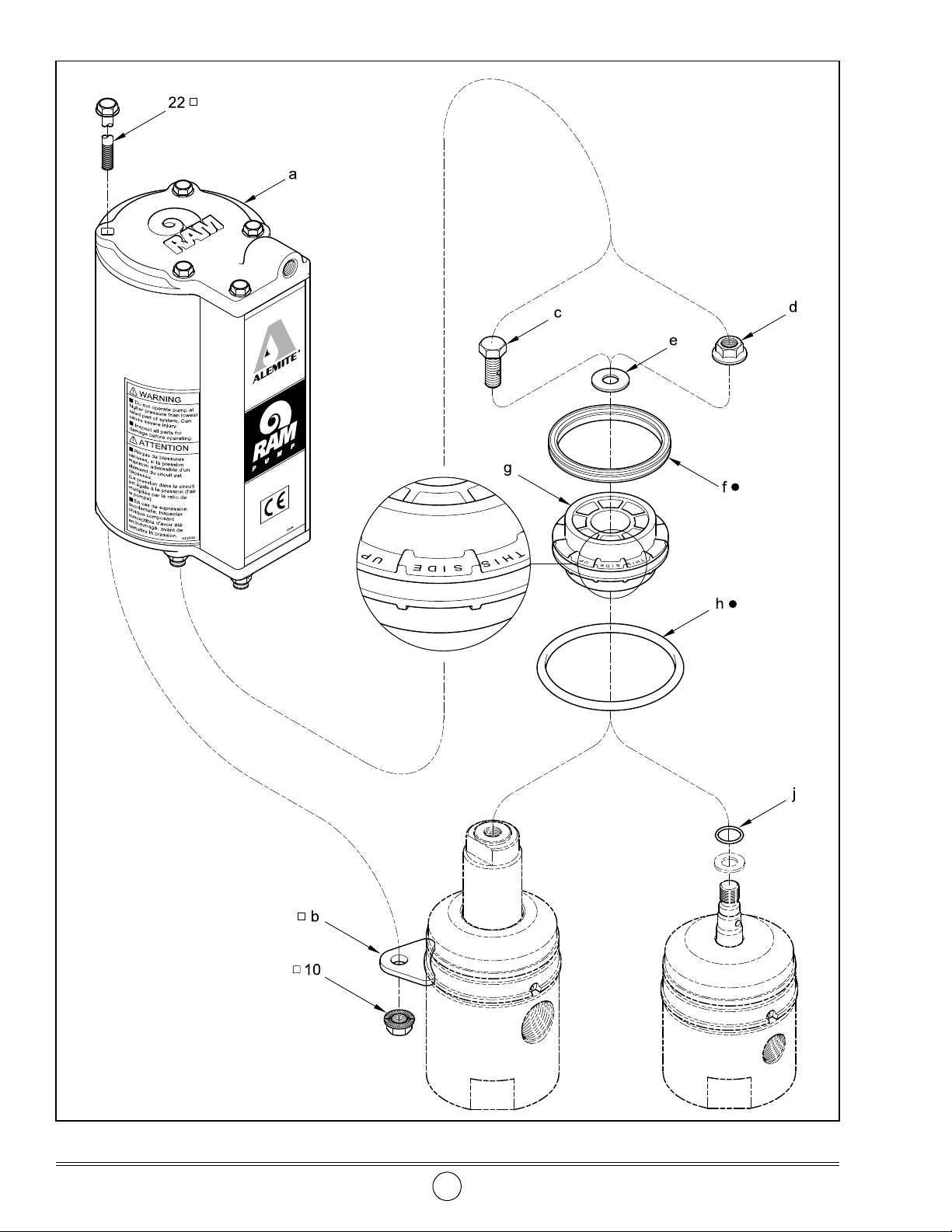
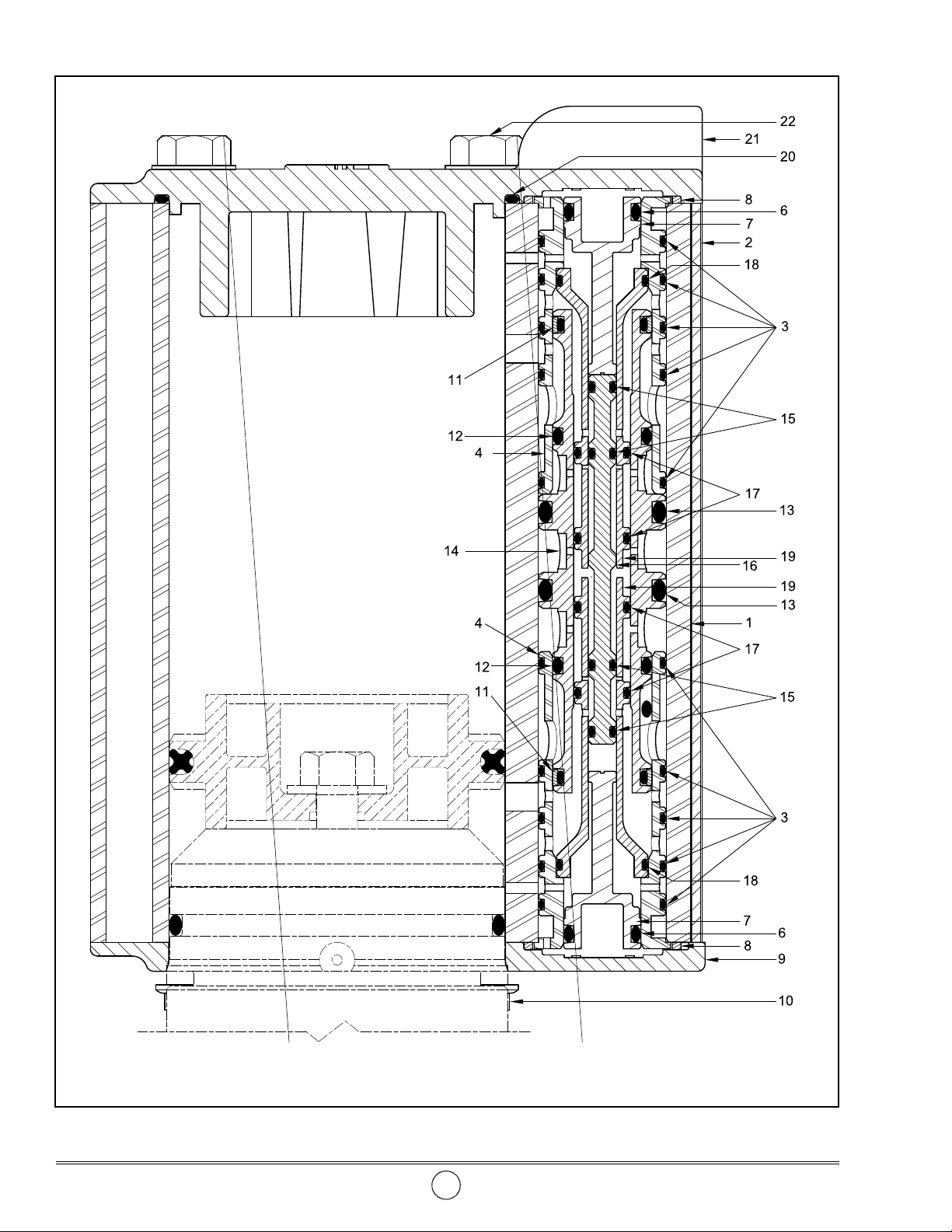
NOTE: Refer to Figures 2 and 5for compo-
nent identification on all assembly proce-
dures.
Air Motor
IMPORTANT: Always use Magnalube-G
Teflon grease in this air motor.
Valve Replacement
NOTE: Procedural steps 1 -4 are applicable
to the Valve Replacement Kit.
1. Remove the Exhaust Adapter and O-Ring assembly
(with Pilot Piston assembly) from one end of the valve
kit.
IMPORTANT: Use care during the assembly
of the logic components. Prevent possible
damage to Seals.
2. Install and seat the remainder of the valve kit assembly
into one end of Cylinder (1).
3. Install and seat the Exhaust Adapter assembly into the
Cylinder and logic components.
4. Install the Pilot Piston assembly into the Cylinder.
Cylinder
HINT: Fill the Gasket groove and the
O-Ring groove in Top Cap (21) with Teflon
grease.
Fill the Gasket groove in Bottom Cap (9)
with Teflon grease.
5. Install Gaskets (8) into Top Cap (21) and Bottom Cap
(9).
• Make sure the Gaskets seat properly.
6. Install O-Ring (20) into the Top Cap.
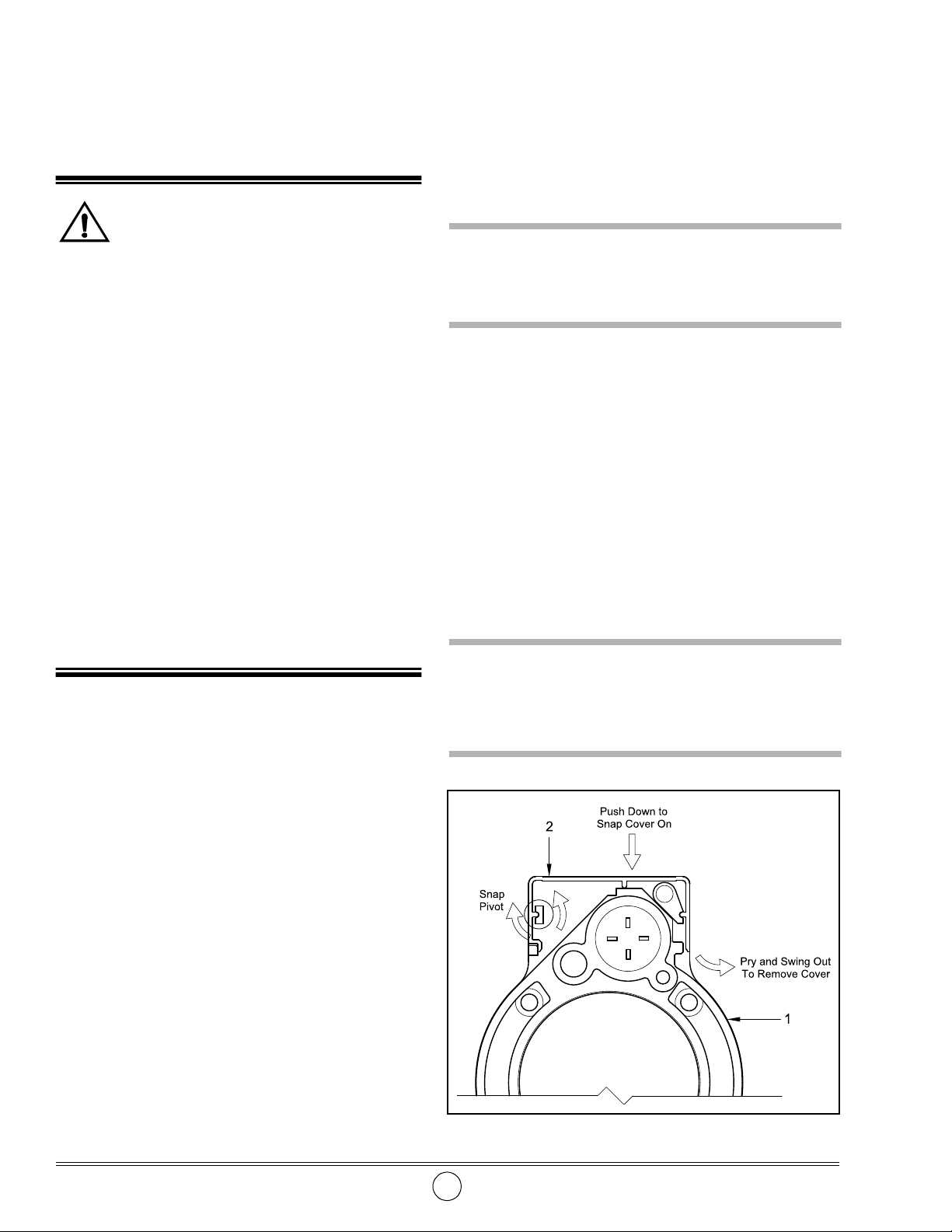
7. Install Muffler (5) into Cover (2).
Attach Air Motor to Pump Tube
Refer to the Pump SER Service Guide for details.
Bench Test and Operation
Refer to the Pump SER Service Guide for details.
Check the motor for air leakage. If the motor leaks,
refer to the Troubleshooting Chart for details.
Installation
General
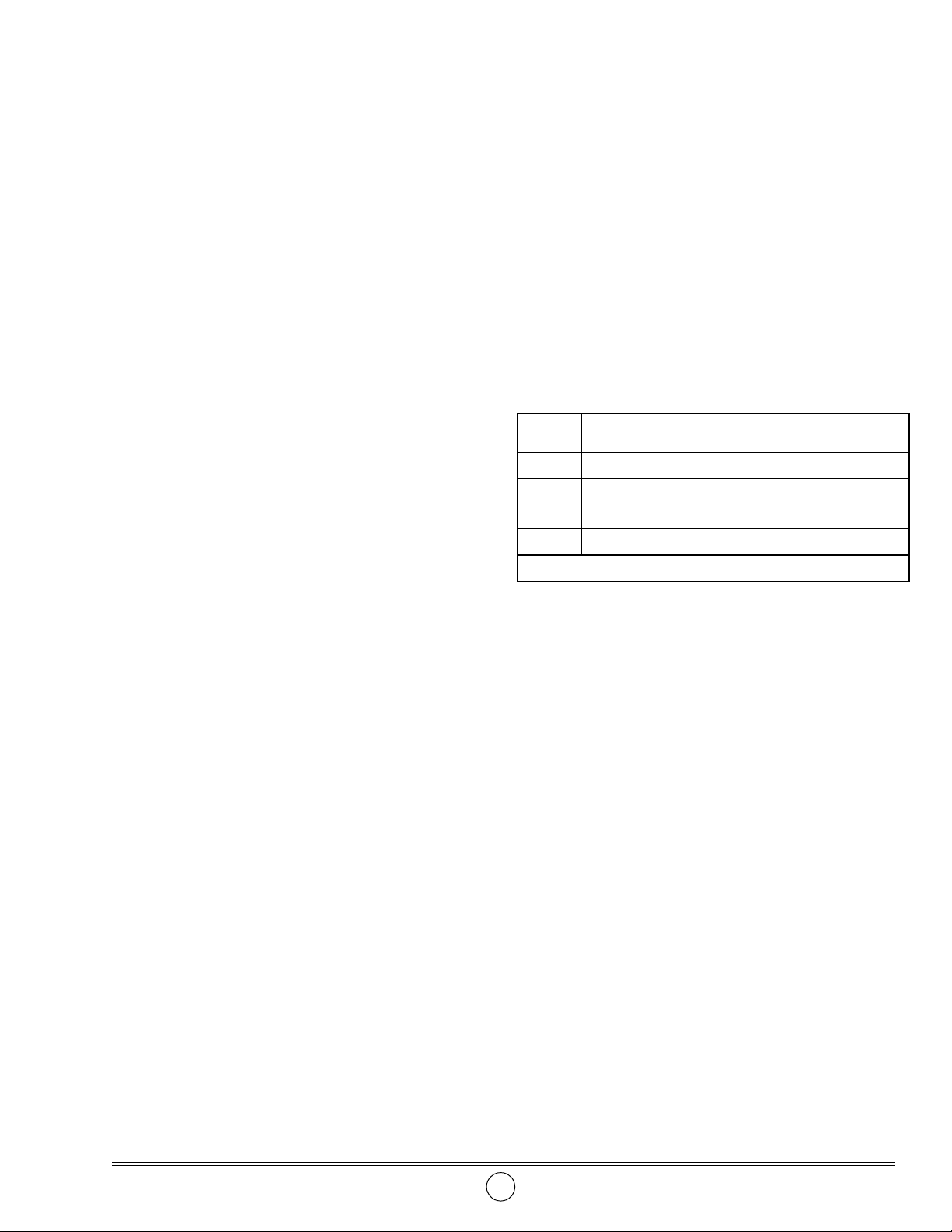
Additional items that should be incorporated into the
air piping system are listed in Table 1.
Upgrade Kit (Conversion)
NOTE: The Air Motor must be separated
prior to installation onto the pump.
a. Remove Cover (2) from the Air Motor.
b. Remove Flange Nuts (10) and Screws
(22) from the Air Motor.
c. Separate Top Cap (21) from Cylinder (1),
and the Cylinder from Bottom Cap (9).
1. Remove the PML motor from the pump.
2. Remove the air motor piston from the rod.
• Discard the piston and o-ring assembly.
3. Remove the o-ring from the body of the pump and
discard.
4. Install and secure Piston (g) onto the rod.
5. Install lubricated Quad-Ring (f) onto the Piston.
6. Lubricate the bore of Cylinder (1) with Magnalube-G
Teflon grease.
7. Install Bottom Cap (9) onto the pump’s body.
8. Install lubricated O-Ring (h) onto the upper groove of
the pump body.
Part
Number Description
338860 Regulator, Gauge, Separator Combination (w/ Auto Dump)
7604-B Regulator and Gauge (Included with 338860)
5604-2 Moisture Separator (Included with 338860)
5904-2 Lubricator *
* Not recommended, use only as required.
Table 1 Air Line Components

SER 339413 Air Motor
Revision (7-06) 8 Alemite, LLC
Figure 5 Air Motor Model 339413 Series- Section View
Refer to Figure 2 Parts List for Parts Identification

Air Motor SER 339413
Alemite, LLC 9 Revision (7-06)
CAUTION
Install Cylinder (1) with care. Damage to Quad-
Ring (f) and/or O-Ring (h) can occur.
HINT: Angle the Cylinder onto the Quad-Ring.
9. Install the Cylinder over the O-Ring and seat it
properly onto the Bottom Cap.
10. Install Top Cap (21) onto the Cylinder.
11. Install Keeper (b) into the groove of the body.
• Make sure the hole aligns with Screws (22).
12. Install one Screw through the Air Motor and through
the Keeper.
13. Install Flange Nut (10).
• Do not tighten the Flange Nut at this time.
14. Repeat procedural steps 11 - 13 for the additional
Keepers and Screws.
15. Install remaining Screw (22) and Flange Nut (10).
CAUTION
Do not overtighten Flange Nuts (10). Component
damage can occur.
16. Torque each Flange Nut in an alternate pattern from
60 to 70 inch-pounds (6.8 - 7.9 Nm).
17. "Snap" Cover (2) onto the Cylinder.
Troubleshooting Chart
Indications Possible Problems Solution
Air motor does not cycle 1. Insufficient air pressure
2. Jammed air valve assembly
3. Pump tube jammed and/or contains loose
components
1. Increase air pressure *
2. Rebuild or replace air valve
assembly
3. Rebuild pump tube
Air motor blows air at
exhaust
Missing Seal(s) Disassemble air motor, clean, inspect,
and install Seal(s).
Lubricate with Magnalube-G Teflon
grease.
Air motor cycles and slight
air leakage at exhaust
Worn or damaged Seal(s) Disassemble air motor, clean, inspect,
and replace worn or damaged
Seal(s).
Lubricate with Magnalube-G Teflon
grease.
Slight air leakage at top
and/or bottom of Cylinder
(1)
1. Gasket (8) installed incorrectly
2. Damaged Gasket (8)
3. Initial tightening of Nuts (10) not sufficient
1. Reinstall Gasket (8)
2. Replace Gasket (8)
3. Tighten Nuts (10)
Slight air leakage at top of
Cylinder (1)
1. Damaged O-Ring (20)
2. Initial tightening of Nuts (10) not sufficient
1. Replace O-Ring (20)
2. Tighten Nuts (10)
* To ''jump start'' a virgin motor, disconnect the air line and apply a maximum of 100 psi (6.9 bar) to the motor’s
connector in a quick ''install and release'' motion.
Changes Since Last Printing
Replaced Screws 339425 with 340348

SER 339413 Air Motor
Revision (7-06) 10 Alemite, LLC
This manual suits for next models
1
Table of contents
Other Alemite Engine manuals