PIAGGIO 500 cc User manual

SERVICE
STATION
MANUAL
Piaggio & C. S.p.A.
Pontedera
After Sales Service
Dis. 594766 - 04/01
Grafica e Stampa:
C.L.D. - Pontedera (PI)
“© Copyright 2001 - PIAGGIO & C. S.p.A. Pontedera.
All rights reserved.”
Data are subject to modification without notice.
We decline all liability for the use of non-original spare parts or accessories that have not been tested and/or approved.
• Engine 500 cc

SERVICE STATION MANUAL
X9 500 cc
This manual has been prepared by Piaggio & C. S.p.A. for use in the workshops of authorised Piaggio dealers and
sub-agents.
It is assumed that the person utilising this manual for servicing or repairing Piaggio vehicles has a knowledge of the
principles of mechanics and standard procedures for vehicle repair. Any important changes in vehicle characteristics
or specific repair operations will be divulged by means of updates to this manual.
Satisfactory repair or service cannot be achieved without the necessary equipment and tools. Refer to the pages
of this manual concerning specific tools and equipment and the special tools catalogue.
Critical information in the manual is indicated as follows.
N.B.: Important information for facilitating and explaining a procedure.
- Procedures that must be followed to avoid damage to the vehicle.
- Procedures that must be followed to eliminate the risk of injury to repair / service personnel.
Warning
Caution

TABLE OF CONTENTS
GENERAL INFORMATION AND
MAINTENANCE
SPECIFIC TOOLS
AUTOMATIC TRANSMISSION
FINAL REDUCTION
FLYWHEEL AND STARTING SYSTEM
THERMAL UNIT AND TIMING SYSTEM
CRANKCASE AND DRIVING SHAFT
INJECTION
LUBRICATION
FLYWHEEL COVER
10
9
8
7
6
5
4
3
2
1
COOLING SYSTEM
STARTER 12
11

TABLE OF CONTENTS
GENERAL INFORMATION AND
MAINTENANCE 1

1 - 2
General information and Maintenance
Safety prescriptions
- If the work to be carried out requires the vehicle
engine to be running, make sure the workshop is
well ventilated and use proper exhausters. Do not
run the engine in closed places. Exhaust fumes are
toxic.
- Battery electrolyte contains sulphuric acid. Protect
the eyes, clothes and skin. Sulphuric acid is highly
corrosive, if it comes into contact with eyes or skin,
wash the affected area abundantly with water and
seek immediate medical assistance.
- The battery produces hydrogen gas which is poten-
tially explosive. Do not smoke near the battery and
keep naked flames and sparks well clear, especially
when the battery is on charge.
- Petrol is highly flammable and can be explosive in
certain conditions. Do not smoke in the work area
and do not introduce naked flames or sparks.
- Clean brake shoes, drums and pads in a well
ventilated place. When using compressed air direct
the jet away from you to avoid inhaling the dust.
Although the brake linings are asbetos-free, inhala-
tion of the resulting dust is harmful.
Maintenance regulations
- Use only genuine PIAGGIO spare parts and recom-
mended lubricants. The use of non-original or non-
conforming spare parts can cause damage to the
vehicle.
- The only specific tools that can be used are those
expressly designed for this vehicle.
- Always fit new gaskets, seal rings and split pins when
reassembling parts.
- After disassembly, clean parts with non-flammable
solvent or a solvent with a high flash point. Lubricate
all surfaces before reassembly with the exception of
conical couplings.
- After reassembling, check that all the components
are correctly installed and that they work perfectly.
- Use only metric tools for disassembly, assembly and
maintenance work. Metric screws, nuts and bolts
cannot be interchanged with BS components. The
vehicle may be damaged if unsuitable tools or nuts,
bolts or screws are used.
- When working on the electrical system, ensure elec-
trical components are correctly installed, paying par-
ticular attention to ground and battery connections.

1
1 - 3
Specifications (500 cc 4-stroke, 4-valves H
2
0 en-
gine)
ENGINE
Type .................................... single-cylinder, 4-stroke
Bore................................................................ 92 mm
Stroke ............................................................. 69 mm
Displacement ............................................... 460 cm
3
Compression ratio ......................................... 10.5 : 1
Timing ............................ chain-operated overhead sin-
gle-shaft flywheel side, inte-
grated phonic wheel, 4-
valves and automatic start-
ing valve lifter
Valves play: intake ...................................... 0.20 mm
exhaust ................................... 0.20 mm
Valves play
adjustment................ threaded register on equalizers
Idle speed............................................. 1450±50 rpm
CO% value .................................................... 1±1.5%
Starting system ................................... electric starter
Lubrication...................... trochoid pump (inside the
crankcase), oil filter and pres-
sure adjustment by-pass
Lubrication pressure.......................................... 4 bar
Minimum allowed pressure (at 100°C) ........... 0.8 bar
Fuel system .................... electronic injection with elec-
tric fuel pump, throttle body
Ø 38mm and single injector
Max power
(at crankshaft) .............. 29 kW (39 CV) bei 7250 rpm
Max torque
(at crankshaft) ............ 40 N·m (4 Kgm) bei 5500 rpm
General information and Maintenance
Cooling system............... liquid, by means of motor-
ized pump, 3-way thermo-
stat and electric fan.
Transmission .................. automatic speed variator by
means of expanding pulleys,
V-belt, automatic clutch, re-
duction gear, and transmis-
sion compartment cooling by
air forced-circulation.
Ignition type .................... high efficiency inductive type
integrated with injection, vari-
able spark advance and
separated high voltage coil
Spark advance
(before T.D.C.) ............... variable controlled by injec-
tion power unit
Spark plug ...............................CHAMPION RG 6 YC
NGK CR7 EKB
Engine-wheel ratio ............................ short: 1/11.988
long: 1/ 4.86
Engine oil ....................... SAE 5W/40 exceeding API
SJ specifications
Quantity ........................................................... ~ 1.7 l
Hub oil ............................................... TUTELA ZC 90
Quantity ............................................................ 250cc
Cooling system capacity ................................. ~ 1.8 l
0.15mm
0.15mm

1 - 4
General information and Maintenance
Spark plug
Check and replacement
- Remove the spark plug when the engine
cold. Replace the spark plug every 12,000 Km. The use
of unsuitable control units or spark plugs other than
those specified can seriously damage the engine.
Recommended spark plug: CHAMPION RG 6 YC
NGK CR 7 EKB
- Put the vehicle on its central stand.
- Open the door on the left side of the vehicle by
levering in the recess in the lower part of the door after
removing the screw.
- Disconnect the spark plug high voltage cable cap;
- Unscrew the spark plug with the spanner provided;
check the spark plug to see if the insulator is cracked,
the electrodes are worn out or excessively sooty.
Also check the condition of the sealing washer and
measure the electrodes gap with a suitable thickness
gauge.
Electrode gap: 0.7 - 0.8 mm
- If necessary adjust the gap by carefully bending the
side electrode. If the spark plug has any of the defects
mentioned above replace it with a plug of the recom-
mended type;
- Insert the plug into the hole with the proper inclina-
tion, screw it in fully by hand and then tighten it with
the specially designed spanner.
Tightening torque: 10 N·m (1 Kg·m)
- Push the spark plug cap all the way down onto the
spark plug and then proceed to the reassembly.
01_002
01_001
Warning
Air filter
- Remove the left-hand lower side panel
- Remove the cleaner cap after unscrewing the eight
fixing screws, including one screw of the knob type.
- Pull out the filter element.
- Replace the air filter with a new one.
N.B.: Check and if necessary blow the air filter every
6,000 km. Direct the air jet from the inside to the outside
of the filter (i.e. in the opposite direction to the air flow
during normal engine operation).
- If the vehicle is mostly used on dusty
roads, the air filter needs to be cleaned and replaced at
shorter intervals than indicated in the Maintenance
Schedule.
- Do not run the engine if the air filter is not
in place as this would result in excessive wear of the
cylinder and piston as well as in damage to the throttle
body.
01_004
01_003
Warning
Warning

1
1 - 5
General information and Maintenance
Engine oil level
In four-stroke engines oil is used to lubricate the valve
gear components, the crankshaft bearings and the
thermal unit. A lack of engine oil can cause serious
damage to the engine.
In all four-stroke engines, oil deterioration and con-
sumption are, to some extent, normal, especially during
running-in. Consumption partly depends on the riding
style (for example, constantly riding at full throttle in-
creases oil consumption).
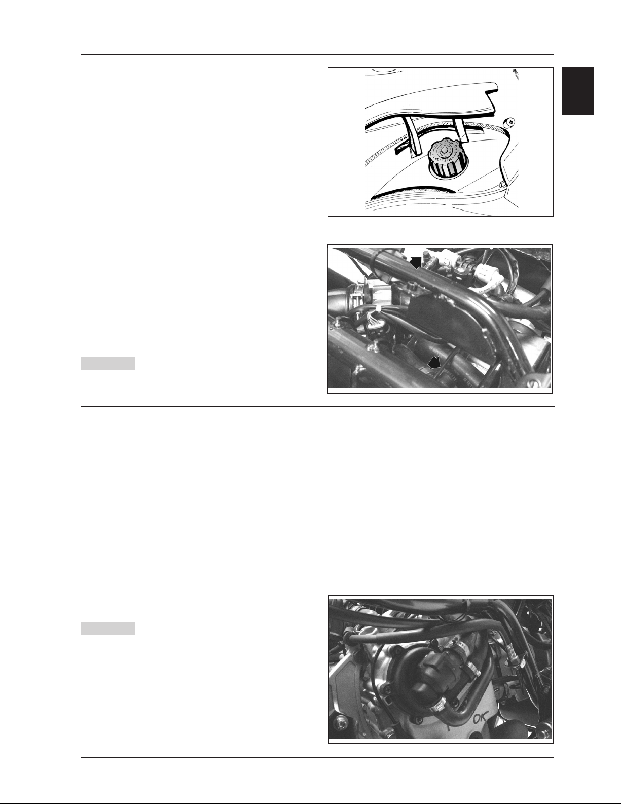
Checking the oil level
Perform this operation when the engine cold, as de-
scribed below:
1) Put the vehicle on its central stand on a flat surface.
2) Unscrew dipstick «A», dry it with a clean cloth and
refit by screwing it completely.
3) Remove the dipstick again and check that the oil
level is between the MAX and MIN marks on the
dipstick; top up if necessary.
Il riferimento del livello di MAX indica una quantità di
circa 1700 cc di olio nel motore.
The level will be lower if checked after using the vehicle
(i.e. when the engine is hot). To obtain a correct indi-
cation of the oil level, wait for at least 10 minutes after
switching off the engine.
Topping up
If the oil level is too low, top up by adding fresh oil
without exceeding the MAX level.
Approximately 400 cc of oil are needed to restore the
level between the MIN and MAX marks.
Oil pressure warning light
A warning light on the instrument panel comes on when
the ignition key is turned to the “ON” position. The light
must go out after the engine has started.
Should the warning light come on while braking,
idling or cornering, check the oil level and the
lubrication system as soon as possible.
Renewing the oil and the filter
The oil and the filter must be renewed every 6,000 km.
Drain all the oil from the engine by removing gauze
strainer drain plug «B» on the transmission side. To
facilitate the outflow, also remove cap/dipstick «A».
Once the oil has drained completely through the drain
hole, unscrew oil filter cartridge «C» and remove it as
described below.
01_005
01_007
01_006
MAX MIN
A
B
C
Since a certain amount of oil remains in the circuit, the
replenishment must be made by adding approximately
1,500 cc of fresh oil through cap «A». Subsequently
start the engine, let it idle for a few minutes and then
switch it off. After about 5 minutes, check the level and
if necessary top up without ex-ceeding the MAX level.
The filter cartridge must be replaced every time the oil
is changed. For top-ups and
renewals use fresh oil of the Selenia HI Scooter 4 Tech
type.
N.B.: Renew the oil when the engine is hot.
When the oil level is at MAX the engine contains
1700 cc of oil.

1 - 6
General information and Maintenance
Replacing the filter
- Do not dispose of the oil in the environ-
ment. Carry out the disposal of the oil, the gasket and
the filter in accordance with the law.
- To avoid burns, take care not to touch
hot engine parts.
- Remove the silencer.
- Remove filler plug «A».
- Remove and clean the drain plug gauze strainer with
compressed air.
- Using a strap wrench for filters, remove cartridge filter
«C».
- Ensure that the O-rings on the prefilter and the drain
plug are in good condition.
- Lubricate the O-rings and then refit the gauze strainer
and the oil drain plug. Tighten the drain plug with the
prescribed torque.
- Fit a new cartridge filter after lubricating the O-ring.
Turn in until the gasket makes contact and then screw
it with the prescribed torque.
- Reinstall the silencer.
- Add engine oil as previously described.
Tightening torque:
Oil filter: 12 - 16 N·m
Recommended oil: Selenia HI Scooter 4 Tech
Checking the hub oil level
- Put the vehicle on the central stand on level ground.
- Unscrew oil dipstick «A», wipe it with a clean cloth,
reinsert it and then screw it in fully.
- Pull out the dipstick again and check that the oil level
is between the MIN and MAX marks (see figure); if the
level is below the MIN mark, top up with oil.
- Reinsert the dipstick and screw it tight.
Renewing the hub oil
- Remove oil filler plug «A».
- Unscrew oil drain plug «B» and drain all the oil.
- Retighten the oil drain plug and then fill the hub with
fresh oil.
Hub oil capacity: ~ 250 cc
Recommended oil: TUTELA ZC 90
Warning
Warning
01_009
01_008
MAX
MIN
A
B
A

1
1 - 7
General information and Maintenance
Water pump
If the water pump becomes noisy or liquid leaks through
the pump drain hole, check the water pump as de-
scribed in Chapter 5-Flywheel cover. Follow these
steps:
- Put the vehicle on the central stand on level ground.
- Remove the lower right-hand side panel and the
right-hand footboard as described in Chapter 8-
Bodywork of the X9- 500 cc manual;
- Remove the sleeves from the water pump cover and
the filler cap from the expansion tank and empty the
cooling circuit.
- Drain the cooling system by removing the sleeves
located on the water pump cover and the plug located
on the expansion tank.
- Perform the operation when the engine
is cold.
- Remove the water pump cover shown in the figure
after loosening the six fixing screws.
- Cooling circuit capacity: ~ 1.8 lt.
- As described in Chapter 5-Engine of the X9 500cc
manual, partially drain the system and overhaul the
pump.
Warning
Engine cooling
Adding coolant and bleeding air from the system.
The level of the fluid must be checked every 6,000 km
when the engine is cold.
Follow these steps:
- Put the vehicle on the central stand on level ground.
- Remove the expansion tank cap and top up if the
coolant is below or near the MIN level in the expansion
tank. The level of the fluid should always be between
the MIN and MAX marks.
- To have an indication of the coolant level, refer to the
groove in the plastic strip that can be seen through the
coolant filler hole. The upper and lower parts of the
groove correspond to the MAX and MIN levels re-
spectively.
- The coolant consists of a 50 percent mixture of
demineralized water and antifreeze solution with a
base of ethylene glycol and corrosion inhibitors.
Total coolant capacity: ~ 1.8 lt
- To check the presence of air in the circuit follow the
procedure described in Chapter 11 - Cooling.
- Switch off the engine and allow it to cool down. After
a few minutes, remove the expansion tank cap and
check the level of the fluid.
- If necessary, top up by pouring fresh coolant into the
expansion tank up to the correct level.
- To prevent the coolant from leaking out
of the expansion tank during use, be sure to never
exceed the MAX level when refilling.
01_011
01_010
Warning
01_012
- After solving the problem and refitting all components,
fill and bleed the cooling circuit again.
N.B.: Change the coolant as described in Chapter 11-
Cooling.

1 - 8
General information and Maintenance
Checking the valve gear timing
- With a wrench of the TORX type, remove the timing
check plug located on the flywheel cover.
- Remove the transmission cover and relevant insula-
tion as described in Chapter 3-Automatic Transmis-
sion.
- Remove the head cover as described in Chapter 7-
Thermal Unit and Timing System.
- Turn the driving shaft by means of the driving pulley
until the reference mark on the magneto support
coincides with the mark on the flywheel cover (TDC).
- Make sure that the reference mark on the phonic
wheel is aligned with the mark on the head. If neces-
sary, turn the driving shaft accordingly.
Valves play check/adjustment
- Check the valves play after aligning the valve timing
reference marks as described in the previous section.
- Check that the valve-register play corresponds with
the indicated values by means of a feeler gauge. If the
valve play values, intake and exhaust respectively,
do not correspond with those indicated below, adjust
them by loosening the check nut and acting on the
register with a screwdriver, as shown in the figure.
Intake: 0.20 mm cold engine
Exhaust: 0.20 mm cold engine
05_233
05_225
01_226
Checking pressure at the end of the compression
- Remove the spark plug cap with the engine cold.
- Remove the spark plug.
- Fit a compression control gauge in the spark plug seat by means of a 10mm plug connection. Tighten to the
prescribed torque.
- Start the engine by means of the starting motor and with throttle body fully open until the gauge pointer stops. If
the pressure is between 8 - 11 bar, remove the tool and reassemble the spark plug.
- If the measured pressure is lower than the recommended values, check the engine revs number; if it is lower than
450 rpm, check the starting system; if the revs number is correct or slightly higher, check the timing. If no troubles
are found, proceed as follows:
- Check that the cylinder gasket is the right one.
- Check the thermal zone sealings (compression rings-valves).
Tightening torque:
Compression test connection: 10 N·m
0.15mm
0.15mm

TABLE OF CONTENTS
SPECIFIC TOOLING 2

2 - 2
Specific tools for Piaggio X9 500 cc 4-stroke 4-valve
Specific Tooling
RECOMMENDED TOOLS
TOOL NAME PART NO.
Circlip pliers 002465Y
Steering thrust ring removing drift 020004Y
Crankshaft aligning tool 020074Y
Support for “METABO HG 1500/2” air heater 020150Y
“METABO HG 1500/2” air heater 020151Y
Mityvac-type vacuum pump 020329Y
Stroboscopic gun for two- and four-stroke engines 020330Y
Digital multimeter 020331Y
Single battery charger 020333Y
Multiple battery charger 020334Y
Magnetic stand and dial gauge 020335Y
Engine support connection 020482Y
Engine mount base 020527Y
Engine mount revolving base 020604Y11
= New tools

2 - 3
2
NECESSARY TOOLS
TOOL NAME PART NO.
STEERING SEAT FITTING TOOL, to be fitted with parts 9 - Lower 001330Y
bearing adaptor, 10 - Upper bearing adaptor
Bell Ø 80 mm 001467Y002
20 mm pliers 001467Y006
Bell Ø 63 mm 001467Y007
18 mm pliers 001467Y008
Bell Ø 45 mm 001467Y017
Bell Ø 60 mm 001467Y031
15 mm pliers 001467Y034
Hub bearing extraction bell 001467Y035
Steering tube ring spanner 020055Y
Oil pressure gauge 020193Y
Valve seal rings assembly tool 020306Y
37x40 mm adaptor 020358Y
42x47 mm adaptor 020359Y
52x55 mm adaptor 020360Y
20 mm guide (Driven pulley bearings) 020363Y
25 mm guide (Driven pulley bearings) 020364Y
Ø 28x30 mm adaptor 020375Y
Adapter sleeve 020376Y
Bushing (valve removing tool) 020382Y012
15 mm guide 020412Y
Valve oil seal extractor 020431Y
Oil pressure gauge unio 020434Y
17 mm guide (countershaft bearings) 020439Y
Driven half pulley spring compressor 020444Y
46-55 mm spanner 020444Y009
Ø 24 mm adaptor 020456Y
Steering tube lower bearing extractor 020458Y
Drift for fitting bearing on steering tube 020459Y
Injection tester kit 020460Y
Flywheel extractor 020467Y
Piston fitting band 020468Y
Injection tester reprogramming kit 020469Y
Piston pin retainer fitting tool 020470Y
Countershaft timing peg 020471Y
Flywheel retaining tool 020472Y
Clutch bell housing retaining tool 020473Y
Drive pulley stop spanner 020474Y
Piston position comparator support 020475Y
Pillar kit 020476Y
Ø 37 mm adaptor 020477Y
Driven pulley needle roller drift 020478Y
Countershaft stop spanner 020479Y
Fuel pressure measuring kit 020480Y
Control unit interface wiring harness 020481Y
30 mm guide 020483Y
Piston stop fork 020512Y
Compass wrench (valve lifter bell stop) 020565Y
Exhaust gas analyser 494929
Specific Tooling

TABLE OF CONTENTS
AUTOMATIC TRANSMISSION 3

3 - 2
AUTOMATIC TRANSMISSION
LUBRICATE WITH OIL APPLY PRODUCT
LUBRICATE WITH GREASE CLEAN WITH CARE ALWAYS REPLACE
WARNING: HANDLE WITH CARE
REFERENCE A B C D E F G H I L M N O P Q
QUANTITY
141117
TORQUE N·m
90-92 23-26 17-20 160-175 65-75 11-13
E
B
A
D
C
F

3 - 3
3
External transmission cover
- Unloose the 5 fixing screws
- Remove the external plastic cover
05_007
05_008
05_009
Transmission cover
- Unloose the 7 fixing screws
- Remove the cover and net filter
N.B.: Disassemble the net filter only if it is to be re-
placed.
Belt antiflapping roller
- Check that the roller is in good condition and that it
turns freely.
- Unloose the fixing screw with a 13 mm wrench
- Remove the roller and relevant bearing.
N.B.: If the roller does not turn freely, replace it.
Driving pulley
- Turn the pulley central nut with a 27 mm wrench to
align the internal holes horizontally, therefore allow-
ing for the specific tool fitting.
Specific tool:
Driving pulley lock wrench 020474Y
05_006
Automatic transmission

3 - 4
- First fit the specific tool stop ring on the pulley until the
groove is fully in contact.
- Afterwards, insert the tool so that the studs on the ring
fit the holes in the tool.
- Tighten, also manually, the two fixing nuts of the tool
- Unloose the central nut.
- Remove the cup washer and the plain washer.
- Remove the fixed driving half pulley.
- Remove the washer to bush connection.
05_011
05_012
- Move the belt downwards.
- Hold the roller stop plate, remove the mobile driving
half pulley with its bush and rear washer, taking care
not to let the rollers come out.
Driven pulley axle support
- To be able to fit the specific tool for removal of the
driven pulley shaft nut, unloose the 2 upper screws of
the driven pulley axle support.
- Manually turn the clutch housing as to partially un-
cover one of the holes in the driven pulley axle
support.
05_010
Automatic transmission
05_013
- Insert the specific tool on the driven pulley axle
support, checking that the tooth fits the hole in the
housing previously uncovered, and that it is resting on
the support.
- Tighten the 2 fixing screws.
- Unloose the driven pulley shaft nut.
Specific tool:
Clutch housing stop tool 020473Y

3 - 5
3
Automatic transmission
- Remove the specific tool
- Unloose the 2 remaining fixing screws of the driven
pulley axle support.
- Remove the driven pulley axle support and the washer.
- Remove the spacer below.
05_014
Clutch housing
- Remove the clutch housing.
05_016
05_015
- Check that the clutch housing shows no signs of wear
or damage.
- Measure the clutch housing I.D.
Standard value: 160.2 mm
Max value: 160.5 mm
N.B.: Check that the measured eccentricity is max 0.2 mm
05_017
Driven pulley assembly
- Remove the driven pulley assembly and relevant belt.

3 - 6
Automatic transmission
Pins stop collar
- Remove the collar by means of 2 screwdrivers.
05_020
Clutch disassembly
- Remove the clutch and driven pulley by means of the
specific tool;
- Prepare the tool with the pins screwed in the «E»
position on the internal side;
- Assemble the driven pulley assembly on the tool and
insert the pins in the ventilation holes;
- Bring the rear stop screw in contact with the fixed
driven pulley, as shown in the figure.
- Put the tool in a vice firmly. Do not
overtighten the rear screw to avoid buckling the tool.
- Remove the fixing ring nut with the specific spanner
of 55 mm.
- Unloose the tool screw and dismount the driven
pulley, clutch, spring with sheath assembly
Specific tools:
Driven pulley spring compressor 020444Y
55 mm spanner 020444Y009
Ring 020444Y010
05_019
05_021
- Remove the 4 guide pins.
- Remove the mobile driven half pulley.
Warning
This manual suits for next models
1
Table of contents
Popular Engine manuals by other brands

Powermat
Powermat PM-SSZ-580 instruction manual

Festo
Festo EMMT-AS Series Instructions & Operating

NOVAK
NOVAK BALLISTIC instructions

Technify Motors
Technify Motors CD-135 Operation and maintenance manual

Saito
Saito FA-200R3 instructions

Briggs & Stratton
Briggs & Stratton Vanguard 540000 Series Operator's manual