3
Alemite, LLC Revision (1-14)
SER 8580
Item #
No. de
artículo#
Pièce n°
Part #
No. de pieza
N° réf. #
Description Descripción Description Qty
Cant.
Qté
Kit
Juego
Kit
Notes
Notas
Remarques
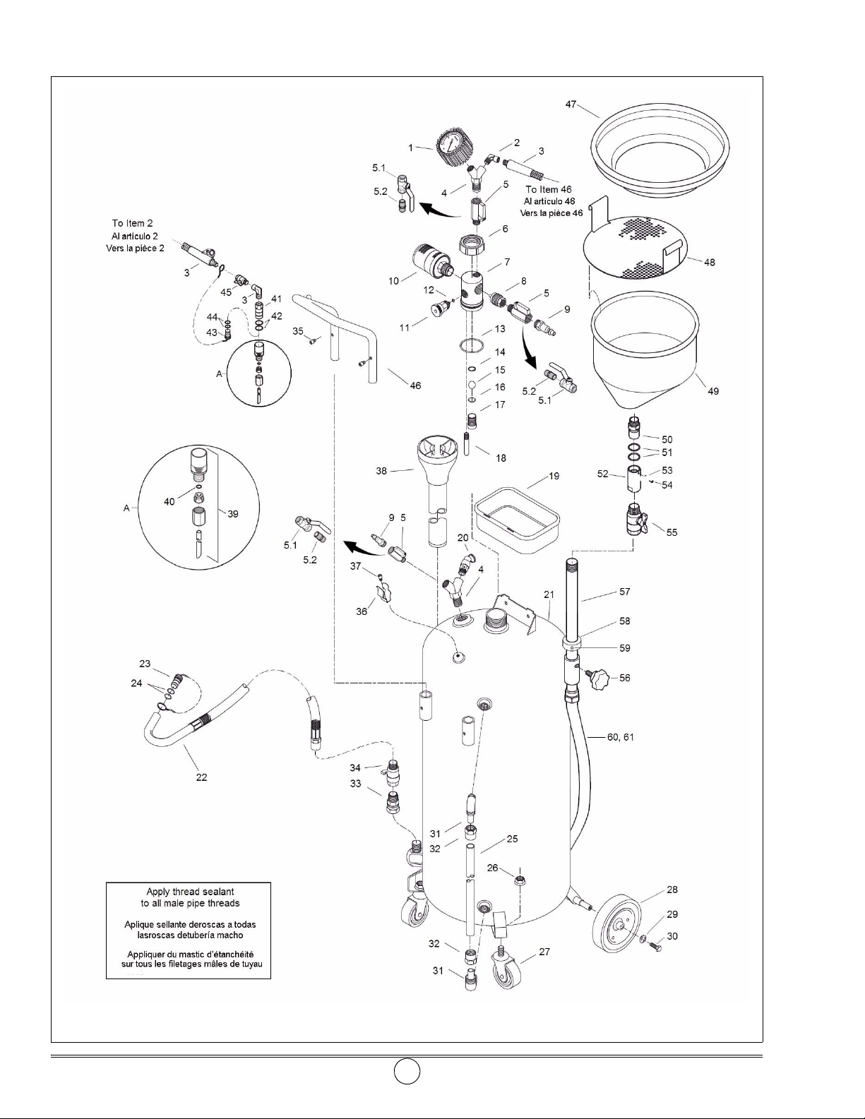
1 393767-19 Gauge, Vacuum Manómetro de vacío Vacuomètre 1
2 Elbow Codo Coude 2
3 393767-20 Hose Manguera Flexible 1
4 393767-5 Adapter, Y Adaptador en Y Raccord en Y 1
5Val ve, Ball Válvula de bola Robinet, boisseau sphérique 3 1/4 " NPTF5.1 SWA288
5.2 327033 Adapter Adaptador Raccord 3
6 Collar Collar Collier 1 □
7 Adapter Adaptador Raccord 1 □
8 Nozzle Boquilla Buse 1 □
9 328034 Connector, Air Conector de aire Raccord, air 2
10 340562 Muffler Silenciador Silencieux 1
11 393767-21 Valve Válvula Robinet 1
12 O-Ring Junta tórica Joint torique 1 ●4.47 mm x 8.03 mm
13 O-Ring Junta tórica Joint torique 1 ●42.5 mm x 47.8 mm
14 Ring, Retaining Anillo de retención Anneau retenue 1 ●
15 Ball Bola Boisseau sphérique 1 ●
16 O-Ring Junta tórica Joint torique 1 ●9.5 mm x 14.8 mm
17 Seat Asiento Siège 1
18 Tube Tubo Tube 1
19 393767-31 Tray, Tool Bandeja de herramientas Plateau, outils 1
20 393767-4 Valve, Relief Válvula de alivio presión Soupape, décharge 1 15 psi (1 bar)
21 Tank Depósito Réservoir 1
22 393767-6 Hose and Nozzle Manguera y boquilla Flexible et buse 1
23 393767-7 Plug and Chain Tapón y cadena Obturateur et chaîne 1
24 O-Ring Junta tórica Joint torique 2 11.2 mm x 16 mm
25 393767-8 Gauge, Level Indicador de nivel Jauge, niveau 1 ●
26 Nut, Flange Tuerca embridada Écrou, embase 2 Δ
27 Caster Rueda orientable Roulette 2 Δ
28 Wheel Rueda Roue 2 ▲
29 Washer Arandela Rondelle 2 ▲
30 Screw Tornillo Vis 2 ▲
31 393767-26 Elbow (set of 2) Codo de codos (2) Coude (jeu de 2) 1
32 393767-27 Ring (set of 2) Conjunto de anillos (2) Bague (jeu de ) 1
33 Adapter Adaptador Raccord 1 1/2 " BSP (f) x 1/2 "
34 Valve, Ball Válvula de bola Robinet, boisseau sphérique 1 1/2 " NPTF
35 Screw Tornillo Vis 2
36 Clip Presilla Attache 1
37 Screw Tornillo Vis 1
38 Container Recipiente Auge 1
39 393767-22 Wand Set (6) Conjunto de varillas (6) Jeu de lances (6) 1
40 O-Ring Junta tórica Joint torique
2
•
5 mm x 8.6 mm
2 6 mm x 9.6 mm
1 6.9 mm x 10.5 mm
1 8 mm x 11.6 mm
41 Connector Conector Connecteur 1 ○
42 O-Ring Juna tórica Joint torique 2 ○● 13.2 mm x 16.8 mm
43 Plug and Chain Tapón y cadena Obturateur et chaîne 1 ○
44 O-Ring Junta tórica Joint torique 2 ○● 6.9 mm x 10.5 mm
45 Valve, Ball Válvula de bola Robinet, boisseau sphérique 1 1/4 " NPTF
46 Handle Asa Poignée 1
47 393767-1 Guard, Splash Protector contra salpicaduras Pare-éclaboussures 1
48 393767-32 Strainer Colador Crépine 1
49 393767-2 Bowl Cubeta Entonnoir 1
50 Stem,Swivel Vástago giratorio Tige, à pivotante 1 ■
51 O-ring Junta tόrica Joint torique 2 ■28 mm x 33.3mm
52 Body, Swival Cuerpo giratorio Corps, pivotant 1 ■
53 Washer, Lock Arandela de traba Rondelle, frein 1 ■
54 Screw Tornillo Vis 1 ■
55 Valve, ball Válvula de bola Robinet, boisseau sphérique 1 3/4 " NPTF
56 Wheel, Hand Rueda manual Molette 1 ♦
57 Extention Tube Tubo de extensión Tube de rallonge 1 ♦
58 Collar Collar Collier 1 ♦
59 Screw, Set Tornillo de presión Vis, de pression 1 ♦M8-1 x 8mm
60 Hose Assy Conjunto de la manguera Flexible 1 ◊
61 Elbow Codo Coude 1 ◊3/4" NPT
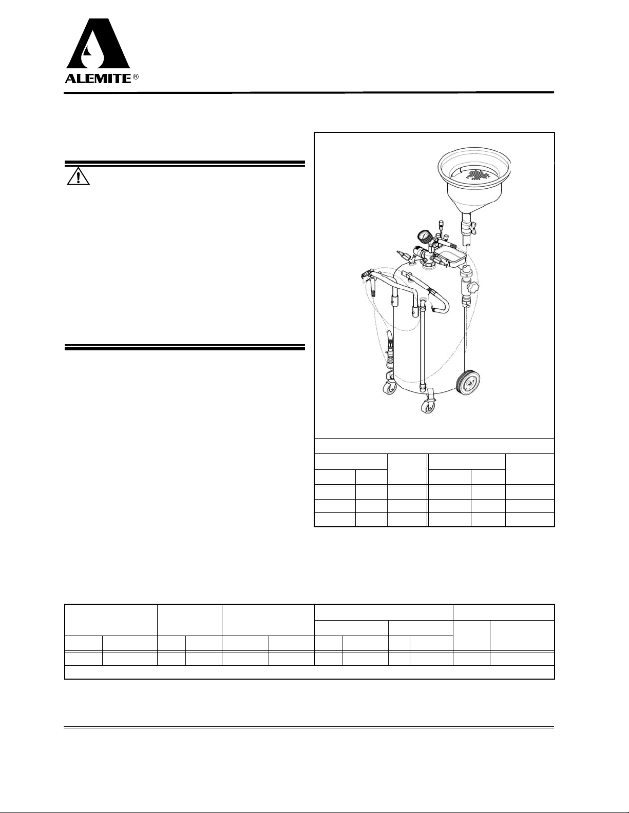
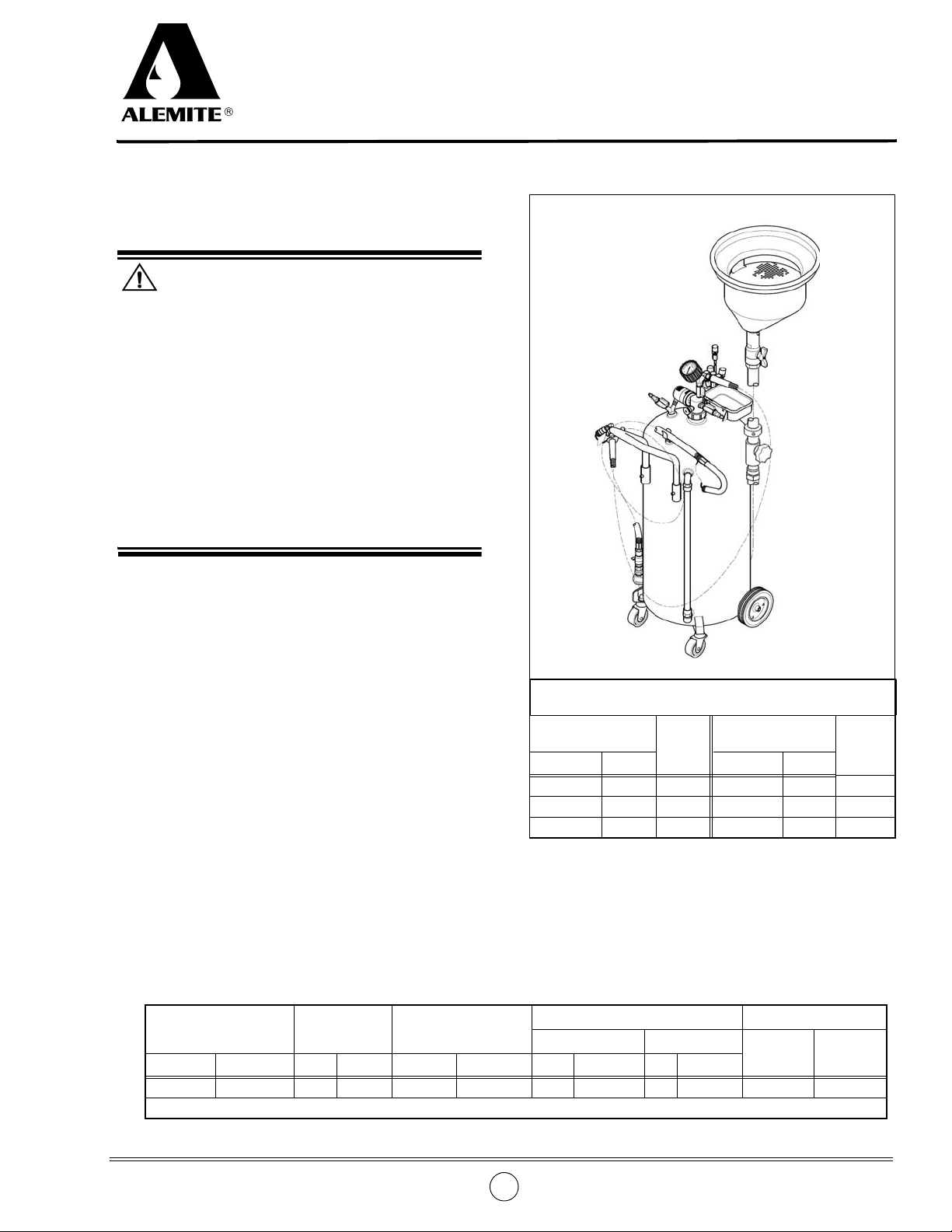
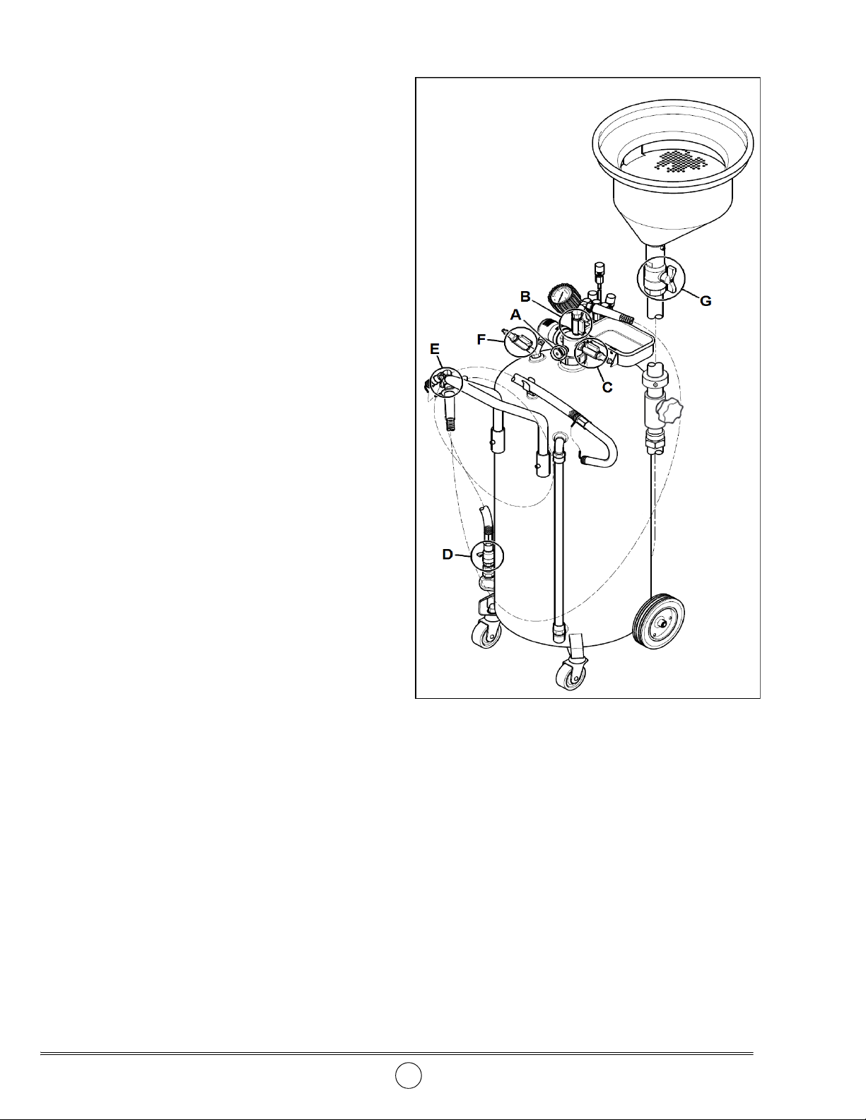
Portable Oil Drain/Extractor