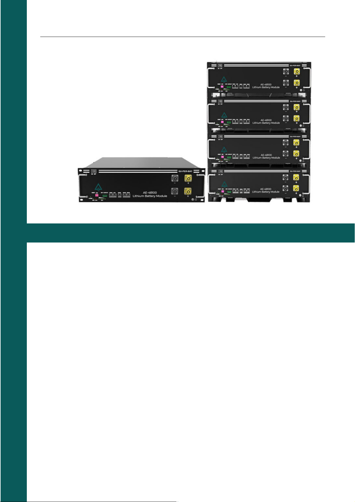
AE-48100 Lithium Battery Module User Manual
Safety Precautions
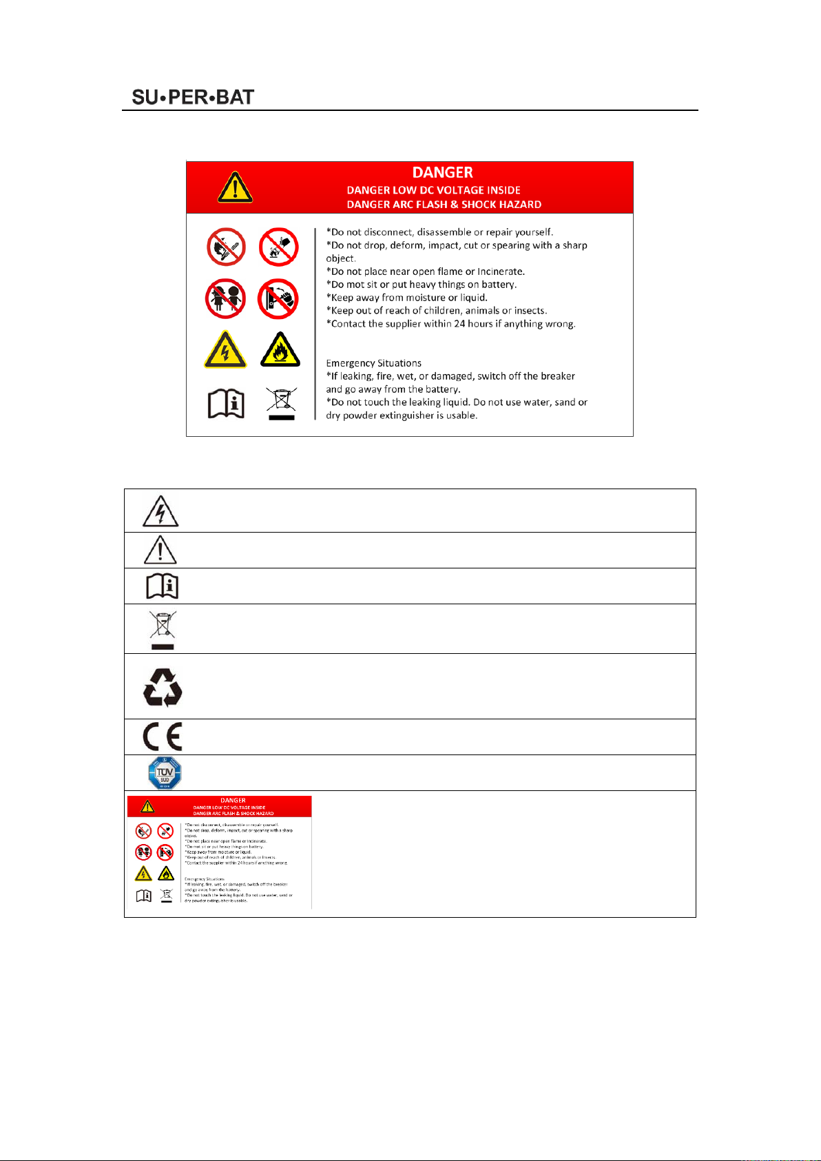
Warning
Please do not put the battery into water or fire, in case of explosion or any other situation
that might endanger your life.
Please connect wires properly while installation, do not reverse connect.
To avoid short circuit, please do not connect positive and negative poles with conductor on
the same device.
Please avoid any form of damage to the battery, especially stab, hit, trample or strike.
Please shut off the power completely when removing the device or reconnecting wires
during the daily use or it could cause the danger of electric shock.
Please use extinguisher to put out the flame when encountering a fire hazard.
For your safety, please do not arbitrarily dismantle any component in any circumstances.
The maintenance must be implemented by authorized technical personnel or our company’s
technical support. Device breakdown due to unauthorized operation will not be covered
under warranty.
Caution
Our product has been strictly inspected before shipment. Please contact us if you find any
abnormal phenomena such as device outer case bulging.
The product shall be grounded properly before use in order to ensure your safety.
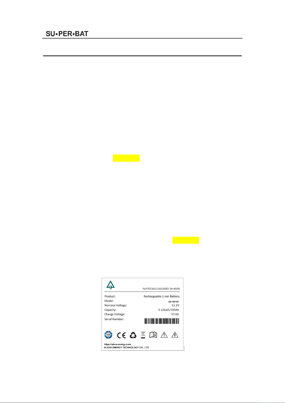
To assure the proper use please make sure parameters among the relevant are compatible
and matched.
Please do not mixed-use batteries from different manufacturers, different types and models,
as well as old and new together.
Ambient and storage method could impact the product life span, please comply with the
operation environment instruction to ensure device works in proper condition.
For long-term storage, the battery should be recharged once every 6 months, and the
amount of electric charge shall exceed 80% of the rated capacity.
Formula of theoretical standby time: T=C/I (T is standby time, C is the battery capacity, I is
total current of all loads).