CARACTERÍSTICAS DEL
PANEL FRONTAL
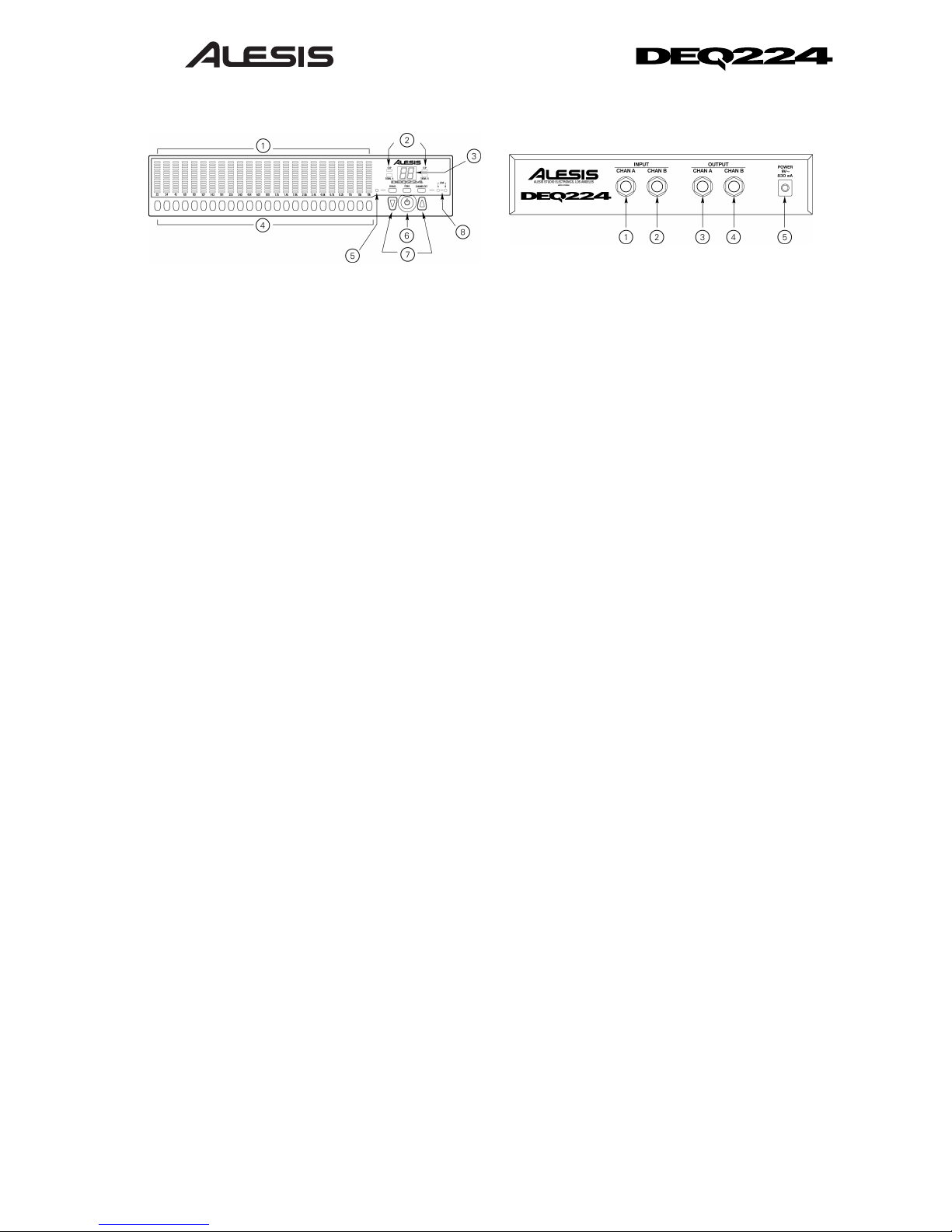
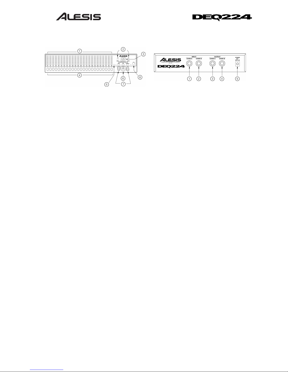
1. Indicadores LED con ganancia de banda:
Para cada banda de frecuencia, indique la
cantidad de atenuación/refuerzo
(Cut/Boost) que ha sido aplicada.
2. Indicadores LED de Señal/Clip: Muestra
los niveles de entrada de audio.
3. 7-Visualización de segmento: Muestra el
programa seleccionado y la cantidad de
atenuación/refuerzo (Cut/Boost) cuando se
edita una banda.
4. Botones de selección de banda: Pulse
estos botones para seleccionar una banda
específica que desee editar.
5. Indicador LED de derivación: Indica que
el ecualizador se ha derivado.
6. Botón de alimentación: Enciende y apaga
la unidad.
7. Botones hacia Arriba/Abajo: Cambia el
programa o aumenta o disminuye los
valores de la ganancia de banda.
8. Indicadores LED de Enlace/A/B: Indica si
la visualización actual de curva es para el
canal A, para el canal B o si está conectado
al estéreo.
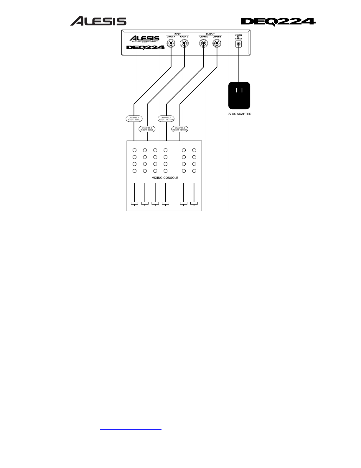
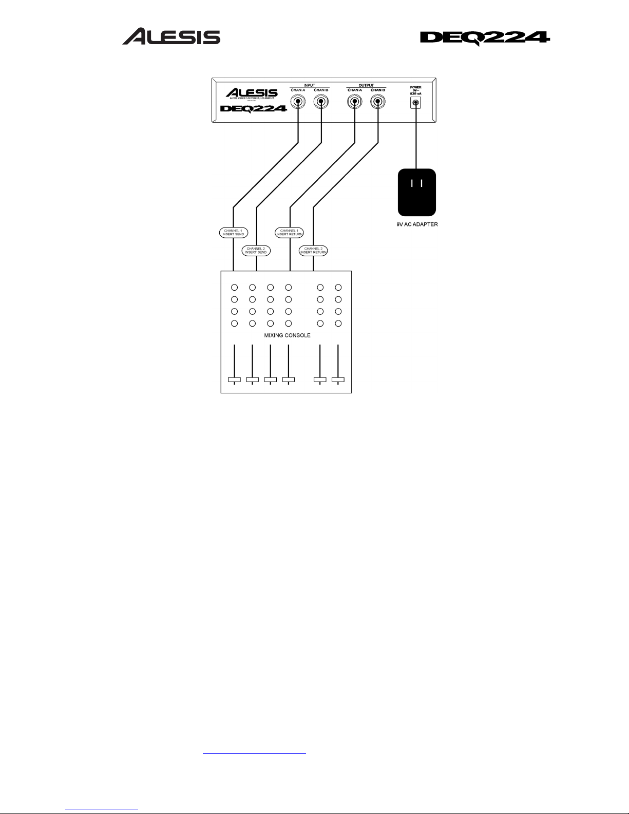
CARACTERÍSTICAS DEL
PANEL TRASERO
Nota: Es recomendable apagar el DEQ224
antes de conectar y desconectar cualquier
fuente a las entradas del mezclador.
1. Entrada del Canal A: Entrada al Canal A
con nivel de línea balanceada de ¼
pulgadas. -10dBV de entrada nominal,
+5dBV de entrada máxima.
2. Entrada del Canal B: Entrada al Canal B
con nivel de línea balanceada de ¼
pulgadas. -10dBV de entrada nominal,
+5dBV de entrada máxima.
3. Salida del Canal A: Salida al Canal A con
nivel de línea balanceada de ¼ pulgadas. -
10dBV de salida nominal, +5dBV de salida
máxima.
4. Salida del Canal B: Salida al Canal B con
nivel de línea balanceada de ¼ pulgadas. -
10dBV de salida nominal, +5dBV de salida
máxima.
5. Entrada de corriente alterna de 9
voltios: Entrada de conector de
alimentación (“barrel jack”) de 9 voltios de
corriente alterna. Conecte solo el suministro
de alimentación “P3” de 9 voltios de
corriente alterna del Alesis a este conector.
Conectar cualquier otro suministro de
alimentación a este conector podría causar
daños irreparables a la unidad.