Algodue ELETTRONICA FCA3000 User manual

FCA3000
Multilingual manual
ENGLISH………………………………………….…p. 2
ITALIANO…………………………………..………p. 14
Ed1401

FCA3000
FLEXIBLE CLAMPS ADAPTER
1MAIFCA300004 16/05/2006
1. INTRODUCTION
This manual provides information on the installation, configuration and use of the main instrument functions.
The manual is not intended for general use, but for qualified technicians.
This term indicates a professional and skilled technician, authorised to act in accordance with the safety
standards relating to the dangers posed by electric current.
This person must also have basic first aid training and be in possession of suitable Personal Protective
Equipment.
WARNING!
It is strictly forbidden for anyone who does not fulfill the above-mentioned
requirements to install or use the instrument.
The instrument complies with the European Union directives in force, as well as with the technical standards
implementing these requirements, as certified by the CE mark on the device and on this Manual.
Using the meter for purposes other than intended ones, understood by the manual content, is strictly forbidden.
The information herein contained shall not be shared with third parties. Any duplication of this manual, either
partial or total, not authorised in writing by the Manufacturer and obtained by photocopying, duplicating or
using any other electronic means, violates the terms of copyright and is punishable by law.
Any brands quoted in the publication belong to the legitimate registered owners.
NOTE
This manual describes the use of the main instrument functions.
USER'S MANUAL
2

3
2. GRAPHIC SYMBOLS
Some instructions in the manual and on the device are highlighted by graphic symbols to draw the reader’s
attention to the operational dangers. The following graphic symbols are used:
DANGER!
This warning indicates the possible presence of voltage exceeding 1kV on
the marked terminals (even if for short periods).
WARNING!
This warning indicates the possible occurrence of an event which may cause
a serious accident or considerable damage to the device if suitable precau-
tionary countermeasures are not taken.
ATTENTION!
This warning indicates the possible occurrence of an event which may cause
a light accident or damage to the device if suitable precautionary counter-
measures are not taken.
NOTE
This warning indicates important information which must be read carefully.
3. DESCRIPTION
FCA3000 is a three-phase converter with DC outputs (current or voltage), which convert the value measured
by a Rogowski coil into true RMS value.
FCA3000has3inputschannelssuitablefor3transducers;the4outputsarededicatedoneforeachtransducer,
the fourth gives the sum of the 3 current values.
These outputs can be used with any kind of indicating device such as voltmeter, oscilloscope, data logger,
SCADA systems, protection systems, metering equipments, etc.
FCA3000 can be used both with rigid and flexible transducers.
4. PRELIMINARY CHECKS
NOTE
At the opening the box, check that the instrument has not been damaged
during transport.
If the instrument appears to be damaged, contact the aftersale service.
The box contains:
the instrument
the user's manual
•
•

4
5. INSTALLATION
NOTE
The equipment complies with the 89/366/EEC, 73/23/EEC standards and
following amendments. However, if not properly installed, it may generate
a magnetic field and radio interference. This is why compliance with EMC
standards on electromagnetic compatibility is essential.
5.1 ENVIRONMENTAL REQUIREMENTS
The environment in which the instrument is installed must satisfy the following features:
No vibrations
Indoor area
Operating temperature between -10°C and +50°C
Storage temperature between -25°C and +60°C
Max humidity 75% (no condensation)
altitude up to 2000m
NOTE
The instrument must not be exposed to sun rays.
5.2 MOUNTING
Fastening to DIN EN 50022 rail is provided for the instrument.
To mount it on the DIN rail, you simply need to use a screw driver as a
lever on the plastic hook on the base of the instrument itself. This operation
will allow to fit the instrument on the DIN rail.
6. SAFETY MEASURES
DANGER!
This warning means that a voltage exceeding 1kV (even if for short periods)
may be present on the terminals.
WARNING!
Electrical instrument connections must be carried out only by skilled techni-
cans who are aware of the risks involved to the presence of voltage. Before
connecting, check the following:
1. the conductor wires are not powered
2. the power supply corresponds to the values on the instrument label
3. the instrument has been installed in a vibration-free environment a suitable temperature (see section 5.1)
4. the terminals are no longer accessible after being connected
5. the wiring is carried out in accordance with the standards in force in the country where the instrument
is to be installed
6. an isolator and an over-current device (e.g. fuse) are installed between the instrument power supply
and the electrical system
7. the connections are made respecting the polarities
8. the connectors are fixed in such a way that they cannot be accidentally disconnected
•
•
•
•
•
•
5
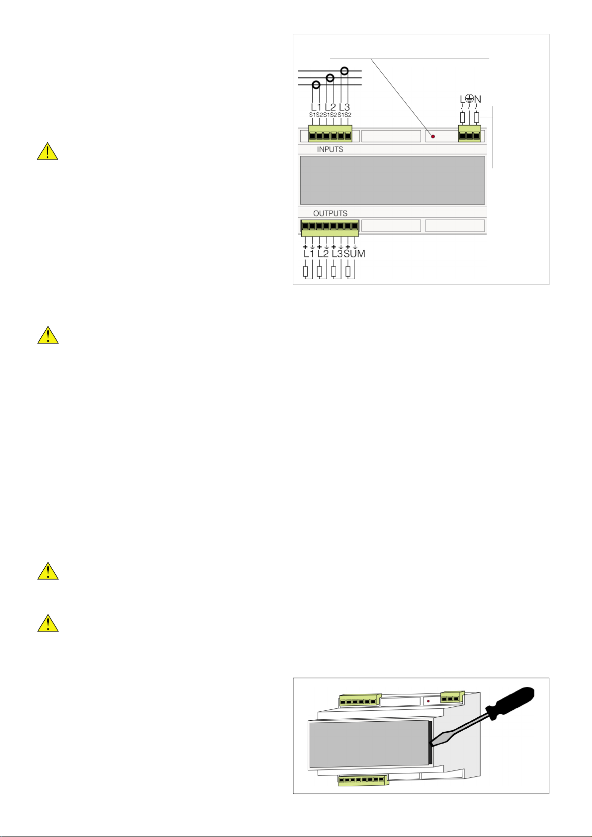
7. CONNECTIONS
Theinstrumentconnectionsarecarriedoutthrough the
following connectors, as indicated in the picture:
a 3-pin female connector (power supply)
a 6-pin female connector (inputs)
a 8-pin female connector (outputs)
WARNING!
Before making any connection, check
if the instrument is switched OFF.
7.1 POWER SUPPLY
WARNING!
Before connecting the power supply, check if it corresponds to the plated
voltage value (80-260 VAC or 19-60VDC).
The instrument does not have a protection fuse on the power supply, therefore the installer must protect it
with a current bracker and an overcurrent protection device (315mA delayed fuse, T type).
7.2 ANALOG INPUTS
The analog inputs allow the connection of 100 mV/kA signal Rogowski coils with 3000A fullscale. On request,
the input value can be customized to allow the connection of rigid or flexible Rogowski coils with fullscale
different from 3000A. Each one of the 3 inputs has 2 terminals; the ground is common to all the outputs.
7.3 ANALOG OUTPUTS
Two different analog outputs types are available: on DC current (standard version), or on DC voltage (on request).
Each one of the 4 inputs has 2 terminals; the ground is common to all the outputs (see picture 7.3).
WARNING!
In case of analog output on DC current, the maximum value of delivered vol-
tage is 10V, therefore the load must never exceed 300 Ohm.
WARNING!
In case of analog output on DC voltage, the internal resistance is 500 Ohm,
therefore the load must never be lower than 100 kOhm.
The maximum output value of 20mA (in case of analog
output on DC current), and of 10 VDC (in case of
analog output on DC voltage), on the SUM output,
corresponds to the sum of the 3 clamps fullscale (e.g.:
3000A clamps, SUM f.s.=9000A).
The instrument is calibrated for the declared accuracy;
if a further fullscale regulation is necessary, remove
the instrument panel, using a screwdriver (see picture
7.2), and operate on the trimmer located inside the
instrument (see picture 7.4, OUT 1, 2, 3, SUM).
•
•
•315mA
fuse, to be
mounted ifthe
neutral is not
identified.
LED ON = Power supply ON
LED OFF = Power supply OFF
Pict. 7.1 - Connections
Pict. 7.2 - Front panel opening

6
DC Current DC Voltage
Pict. 7.3 - Analog outputs diagram
In case of instrument with 4-20 mA output (only on
request), the 4 mA output can be regulated operating
onthetrimmerlocatedinside theinstrument(see picture
7.4, O 1, 2, 3, SUM).
Pict. 7.4 - Trimmer

7
TRIMMERJUMPER
TRIMMERJUMPER
TRIMMERJUMPER
40% FS
0%
40% FS
0%
40% FS
0%
40% FS
0%
40% FS
0%
40% FS
0%
8. RESPONSE TIME
The waveform shows the relevant output variation and an input variation from 0 to 40% of the signal and
viceversa. The horizontal scale is 50 msec for each column.

8
TRIMMERJUMPER
TRIMMERJUMPER
TRIMMERJUMPER
40% FS
0%
40% FS
0%
40% FS
0%
40% FS
0%
40% FS
0%
40% FS
0%

9
TRIMMERJUMPER
TRIMMERJUMPER
TRIMMERJUMPER
40% FS
0%
40% FS
0%
40% FS
0%
40% FS
0%
40% FS
0%
40% FS
0%

10
TRIMMERJUMPER
TRIMMERJUMPER
TRIMMERJUMPER
40% FS
0%
40% FS
0%
40% FS
0%
40% FS
0%
40% FS
0%
40% FS
0%
Table of contents
Languages:
Popular Media Converter manuals by other brands


H&B
H&B TX-100 Installation and instruction manual

Bolin Technology
Bolin Technology D Series user manual

IFM Electronic
IFM Electronic Efector 400 RN30 Series Device manual

GRASS VALLEY
GRASS VALLEY KUDOSPRO ULC2000 user manual

Linear Technology
Linear Technology DC1523A Demo Manual

Lika
Lika ROTAPULS I28 Series quick start guide

Weidmuller
Weidmuller IE-MC-VL Series Hardware installation guide

Optical Systems Design
Optical Systems Design OSD2139 Series Operator's manual

Tema Telecomunicazioni
Tema Telecomunicazioni AD615/S product manual

KTI Networks
KTI Networks KGC-352 Series installation guide

Gira
Gira 0588 Series operating instructions

Lika
Lika SFA-5000-FD user guide