Numerik Jena LIKgo User manual

English Original Instruction

2/46
INDEX
1. FEATURES AND APPLICATIONS����������������������������������������������������������������������������������4
2. SAFETY�������������������������������������������������������������������������������������������������������������������������������6
2�1 General Information ��������������������������������������������������������������������������������������������������6
2�2 Notes on Legal Requirements�����������������������������������������������������������������������������������7
2�3 Notes on Transport, Storage and Handling���������������������������������������������������������������7
2�4 Notes on Operation���������������������������������������������������������������������������������������������������8
2�5 Notes on Maintenance ����������������������������������������������������������������������������������������������8
2�6 Environmental Protection and Disposal ��������������������������������������������������������������������9
3. TECHNICAL PROPERTIES ���������������������������������������������������������������������������������������������9
3.1 ResolutionandAccuracy(Denition) ������������������������������������������������������������������������9
3�2 Reliability�����������������������������������������������������������������������������������������������������������������11
3�3 Ambient Conditions�������������������������������������������������������������������������������������������������12
3�4 Attainable Traversing Speed �����������������������������������������������������������������������������������12
3.5 OnlineCompensation(OffsetandAmplitudeControl) ��������������������������������������������13
4 TECHNICAL DATA ����������������������������������������������������������������������������������������������������������15
4�1 Mechanical Data �����������������������������������������������������������������������������������������������������15
4�2 Electrical Data���������������������������������������������������������������������������������������������������������19
5. GENERAL INSTALLATION NOTES�����������������������������������������������������������������������������25
5�1 Delivery Contents����������������������������������������������������������������������������������������������������25
5�2 Installation Position �������������������������������������������������������������������������������������������������25
5�3 Mounting Drawing - LIKgo���������������������������������������������������������������������������������������26
5�4 Mounting Steps �������������������������������������������������������������������������������������������������������27

3/46
6. SIGNAL ADJUSTMENT �������������������������������������������������������������������������������������������������34
6�1 Signal Adjustment with ADJUSTMENT TOOL & EPIFLEX-Adapter �����������������������34
6�2 Signal adjustment with NPA - NUMERIK PWT Adapter and PWT 101 �������������������37
6�3� Comparison of the different adjustment variants�����������������������������������������������������40
7. CLEANING������������������������������������������������������������������������������������������������������������������������40
8. TROUBLESHOOTING ����������������������������������������������������������������������������������������������������41
9. ORDERINFORMATION ��������������������������������������������������������������������������������������������������42
9�1 Scanning head LIKgo����������������������������������������������������������������������������������������������42
9�2 Speed Chart for LIKgo Series ���������������������������������������������������������������������������������43
9�3 Scale Tape MI for LIKgo������������������������������������������������������������������������������������������44
9�4 Order Information for Accessories���������������������������������������������������������������������������45

4/46
1. FEATURES AND APPLICATIONS
Position encoders in drive systems have to meet high and controversial demands, especially in
linear drive systems� The demands opposing each other are high accuracy and resolution on
the one hand and low mass, small dimensions and high measuring speed on the other hand�
• The graduated scale is definitive for the quality of a linear encoder� Requirements for
maximumpositiondeviationsof±2μmpermeterorlessarenorarity.Theemphasis
is mostly on the avoidance of shortrange errors, since long-range errors, mostly linear
error components, can often be compensated�
• The concentration of multiple axes in motion in very tight spaces, such as in
semiconductor-producing machines, requires the miniaturization of the drives,
guideways and encoders�
• High machining speeds and therefore high accelerations make low masses of the
components in motion essential�
The LIKgo incremental encoders from NUMERIK JENA are equipped with features which are
supposedtofulllthesehighrequirementsinanidealway.
• Due to an interpolation up to 64-times a resolution down to 78,125 nm is possible
without any additional electronics�
• The permissible traversing speed for a sinusoidal signal output amounts to 10 m/s� A
Squarewavesignaloutputwitharesolutionof0.1μmallowsapermissibletraversing
speed of 1�6 m/s�
• Theshort-rangepositionerrors(interpolationerrors)weresignificantlyreducedby
introducing an electronic compensation of amplitude and offset deviations of the coarse
signals� This compensation functions without following error in all velocity ranges�

5/46
Applications:
• Production and inspection machines for the semiconductor industry
• Linear units, drives and coordinate tables
• Measuring machines and measuring microscopes
• Positioning and measuring devices for medical technology
• Precision devices for reprography
• Precision machining
• Robotics
Additional features:
• Referencesignal(s)withrepeatabilityaccuratetoaspecificincrement,regardlessofthe
directionfromwhichthereferencemark(s)is/aretraversed
• Compact size and large mounting tolerances
• High resistance to contamination due to 2-field scanning
• Possibilityofelectronicsignaladjustment(signaloptimizationaftermounting)
• Special,easytomountscaletape(SINGLEFLEX)foravarietyofapplicationsand
ambient conditions

6/46
2. GENERAL INFORMATION
2.1 Specications and recommendations
• Make sure to familiarize yourself thoroughly with the contents of these installation
instructions before installing and starting up the encoder!
• Please contact the support of NUMERIK JENA GmbH or an authorized representation
for further information� Please visit the NUMERIK JENA website to get the contact
information�
• NUMERIK JENA GmbH is not liable for damages caused by unauthorized handling of
the encoders� Any unauthorized handling leads to forfeiture of all warranty claims�
• The encoders are guaranteed to function if the mounting and operating conditions are
maintained as stated in these mounting instructions�
• Make sure to follow the right sequence of the mounting steps during mounting�
• NUMERIK JENA GmbH does not assume any liability for any damages or operating
errors caused by incorrect installation or operation�
• The stated tolerances must be maintained in order to achieve the accuracies listed in
the specifications!
• If the machine tolerances exceed the tolerances stated in the mounting instructions,
errors can occur in both the operation and during measuring� NUMERIK JENA GmbH
assumes no liability for this�
• Please refer to the operating manuals and safety instructions included with the devices
to ensure the reliable operation of the encoder systems, especially pertaining to:
◦Auxiliary electronic units
◦Counters
◦Displays
◦Controllers
◦Encoders
◦ Basemechanicaldevices(machinetools)

7/46
* In place of IEC 61010-13rdEd�, Section 9�4, the corresponding sections of standards DIN EN 61010-1, EN61010-1,
UL 61010-1 and CAN/CSA-C22�2 No� 61010-1 can be applied and in place of IEC 60950-12nd Ed�, Section 2�5 the corre-
sponding sections of standards DIN EN60950-1, EN60950-1, UL60950-1, CAN/CSA-C22�2 No� 60950-1 can be applied�
Europe
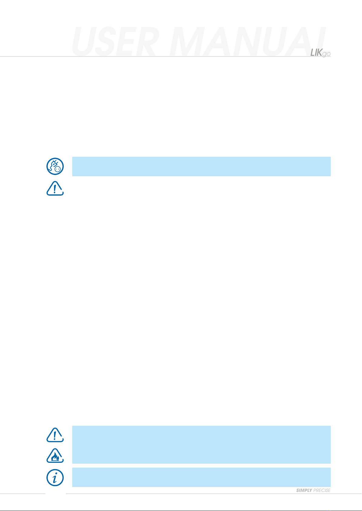
• Please pay attention to the safety instructions and warning symbols!
Danger to the devive or the function of the device!
Pull the plug!
Highlyintammable!
2.2 Notes on Legal Requirements
• The NUMERIK JENA encoders conform to EC standards and carry the
CE mark�
• TheyareconformtoEMC-standards(2014/30/EU)
• NUMERIKJENAencodersfulfilltherequirementsofthe(German)ProductSafetyAct
(ProdSG)fromNovember8th, 2011�
• Connect NUMERIK JENA encoders only to subsequent electronics whose power supply
isgeneratedfromPELVsystems(EN50178).
• NUMERIK JENA encoders fulfill the requirements of standard IEC 61010-1 only if the
power is supplied from a secondary circuit with current limitation as per IEC 610103rd
Ed�, Section 9�4 or with power limitation as per IEC 60950-12nd Ed�, Section 2�5 or from a
Class 2 secondary circuit as specified in UL1310�*
• This user manual supersedes all previous editions, which thereby become invalid� The
basis for ordering from NUMERIK JENA is always the user manual edition valid when
the contract is made�
• Standards(ISO,EN,etc.)applyonlywhereexplicitlystatedintheusermanual.
2.3 Notes on Transport, Storage and Handling
Encoder
Use only the original packaging for transportation! If possible, use only the
original packaging for storage..

8/46
SINGLEFLEX Scale Tape
• Canberolledup(minimumbendingradius=140mm).
• No restrictions regarding to the length�
2.4 Notes on Operation
Do not connect or disconnect plugs if the power is on!
• Only operate the encoder with the supply voltage stated in this product data sheet�
• Comply with applicable PIN assignment if auxiliary electronic units are connected (e�g�
controllerordisplay)!
• Integrate exposed encoders in instruments, devices or machines in such a way that they
are protected against contamination�
• Protect the scale tape against mechanical damage�
• Protect the scanning head against shock, impact and humidity��
2.5 Notes on Maintenance
• The encoder requires no maintenance whatsoever, but must be cleaned occasionally,
depending on the ambient conditions�
• Modifications and repairs of the encoder may only be carried out by NUMERIK JENA
GmbH or appropriately authorized persons�
• NUMERIK JENA GmbH is not liable for damages caused by unauthorized handling of
the encoder� All warranty claims are forfeited by unauthorized handling�
• Exposed measuring systems are sensitive to contamination, especially the scale surface
and the scanning windows for the counting and reference tracks on the scanning head�
• Particularly critical are rough and irregular contamination and deposits (e�g� oil, grease
orwater).
• The user has to protect the encoder from contamination by way of appropriate design
measures�
When cleaning the encoder, ensure that no solvent ows under the scale tape!
When cleaning the components, ensure that the scanning window and scale
tape are not scratched by any deposited particles!
Please also pay attention to the notes in chapter 7 „Cleaning“.

9/46
2.6 Environmental Protection and Disposal
Environmental damage due to incorrect disposal of the product, accessories or peripherals!
• Do not dispose in domestic waste�
• Dispose only by authorized collection points� Electrical waste and electronic components
are subject to special-waste regulations�
• Observe the applicable country-specific regulations�
More detailed information on legal regulations can be obtained from competent authorities�
2.7 Nameplate
Image 1
Product Name
Data Matrix Code
Identitynumber
Serialnumber

10/46
3. TECHNICAL PROPERTIES
3.1 Resolution and Accuracy (Denition)
Basically one has to differentiate between the resolution and the accuracy of a measuring
system� The two parameters are not directly interdependent and may differ from each other�
Resolution
The resolution of linear system describes the least possible displacement of scanning head
againstthescalewhichcanstillbediscernedbytheevaluationelectronics(display,control).It
dependson(seechart1)
• the graduation period of the scale
• thesignalintepolationfactor(internallyorinauxiliaryelectronicunit)
• the evaluation mode in the counter
Chart 1
Accuracy
Theaccuracyoflinearmeasuringsystemsisspeciedinaccuracyclasses.
The extreme error values for any max� one-meter section of the measured length lie within the
speciedaccuracyclassof±aμmwithrespecttotheirmeanvalue.
Formeasuringlengthupto1m,thetolerance(±aμm)referstotheactualmeasuringlengths.
The accuracy applies to a reference temperature of 20°C�
Withexposedlinearmeasuringsystems,thedenitionoftheaccuracyclassappliesonlytothe
scale� This is called scale accuracy�
Grating period
of scale tape
Signal period
of sinusoidal
signals
Interpolation
factor
Signal period
after
interpolation
Resolution after
evaluation
in counter
4-times
20 µm 20 µm
none/1-times 20 µm 5 µm
5-times 4 µm 1 µm
10-times 2 µm 0�5 µm
25-times 0�8 µm 0�2 µm
50-times 0�4 µm 0�1 µm
64-times 312�5 nm 78�125 nm

11/46
3.2 Reliability
With its compact dimensions, the exposed linear encoder from NUMERIK JENA is equipped
withtwoscanningelds.Thescanningsignalsaregeneratedbytwolarge1.1mm²sensor
elds.
Localcontaminationonthemeasuringelementsuchasdust,ngerprintsorparticleshave
only a minor effect on the signal amplitude, as the ASIC SV4 installed in the measuring head
monitors the signals and eliminates any deviations in the amplitude�
If the signal amplitude decreases due to the presence of contamination on the measuring scale,
thesensoramplierreadjustsbyincreasingthesignalamplication.Theoutputsignalsdonot
change in offset and phase position� The result is a constant signal shape�
This measuring system is especially suitable for applications that require high reliability�
Image 2
Fingerprint Wire (50 µm) Oil lm Dust
Signals in VPP
Position in mm
Online compensation active
Online compensation inactive

12/46
3.3 Ambient Conditions
Chart 2
3.4 Attainable Traversing Speed
The maximum attainable traversing speed of the encoder is determined by the maximum
output frequency of the interpolator and/or the maximum counting frequency of the operator‘s
evaluation electronics�
In order to avoid counting errors, the interpolator‘s output frequency is matched to the counting
frequency of the operator‘s evaluation electronics� This adaptation is possible in discrete
frequency steps�
The maximum attainable traversing speed (vmax )iscalculatedaccordingtothefollowing
formula:
f Output frequency set by the manufacturer for 4-times
evaluation by the interpolator [MHz]
TP Grating period [µm]
i Interpolation factor
(5-times,10-times,25-times,50-timesoder64-times)
SF Safety factor = 1�4
vmax = f · TP [m/s]
i · SF · 4
Ambient condition LIKgo
Operating temperature range 0°Cto+55°C(+32°Fto+131°F)
Storage temperature range -20°Cto+70°C(-4°Fto+158°F)
Vibration(50Hz...3000Hz) ≤500m/s2
Shock(6ms) ≤1000m/s2
Humidity(40°C/104°F) 93% relative humidity
(nocondensationforming)

13/46
3.5 Online Compensation (Oset and Amplitude Control)
Contamination and mounting errors lead to interferences in the optical scanning of the scale
by the scanning head and so to periodic deformations of the sinusoidal counting track signals,
whichareexempliedas
• Offset deviations
• Amplitude deviations
• Amplitude differences between the sine and cosine channels
and lead to interpolation errors�
Usin+ Ucos
Usin/Ucos
Usin+ Ucos Usin/Ucos
Usin/Ucos
Usin+ Ucos
Usin+ Ucos
Usin/Ucos
Usin+ Ucos Usin/Ucos
Usin/Ucos
Usin+ Ucos
Usin+ Ucos
Usin/Ucos
Usin+ Ucos Usin/Ucos
Usin/Ucos
Usin+ Ucos
Image 5
Image 4
Image 3
Incorrect Mounting
Scanning head signal with faulty
mounting before activation of the
online compensation�
Active Online Compensation
Scanning head signal with
contaminated scale tape and/or
faulty mounting after activation of the
online compensation�
Contaminated Scale Tape
Scanning head signal with
contaminated scale tape
before activation of the online
compensation�

14/46
The offset and amplitude control automatically corrects the signals generated by the measuring
module within the sensor for the entire speed range without following error over the entire
velocity range� This improves the accuracy as well as the reliability and the functional reserves�

15/46
Chart 3
Permissible Mounting Tolerances
Chart 4
* These cumulative tolerances include mounting tolerances and guideway errors during operation�
The mounting tolerances are only valid for one degree of freedom at a time�
4 TECHNICAL DATA
4.1 Mechanical Data
4.1.1 Encoder LIKgo
Parameter LIKgo
Dimensionsofscanhead(inmm) 28 x 13 x 7�5
Weightofscanhead(w/ocable) 10 g
Traversing speed
depending on auxiliary electronic unit see Speed Chart
Coorinates for LIKgo scanning heads
Working distance
(air gap between sensor and scale)
1�4 mm
Mounting tolerances / Position deviations*
ΔZ=±0.2mm
ΔY=±0.4mm
φZ=±0.2°(±12‘)
φY=±1.0°(±60‘)
φX=±1.0°(±60‘)

16/46
SINGLEFLEX Scale tape MI
Material Stainless Steel
Gratingperiod(TP) 20 µm
Reference marks
• Inthemiddleofthemeasuringlength(ML)
• without
• every 50 mm
• Others on request
Measuringlenght(ML) upto2480mm(othersonrequest)
Linearthermalexpansioncoefcient 10�6 x 10⁻⁶ K-1
(expansionwillbeinuencedbythemountingsurface)
Accuracyclasses(a) • ±3 µm/m
• ±5 µm/m
Baseline error ±750 nm / 50 mm
4.1.2 SINGLEFLEX Scale Tape
8
Zählspur
Referenzspur
Klebeband
Maßband
0.45
0.25
0.20
Adhesive tape
Scale tape
0.45
0.25
0.20
8
Counting track
Reference track
Chart 5
The SINGLEFLEX-scale tape consists of a single steel tape with an applied incremental track
and one reference mark (more reference marks are possible within the scope of a special
design).Thescaletapeisequippedwithadouble-sidedadhesivetapeandcanbemounted
easily on the machine element�
Image 6

17/46
Start of
measuring
length (ML)
End of
measuring
length (ML)
first evaluable
index-mark
Tape length = ML + 15 ±0.5
Position index-mark/cut ±0.5
0,62
8
6
ML/2 10
positive counting direction
Encoder
LIKgo*
CableScale tape MI
* View of the sensor from above through the housing Image 7
Counting Direction
The alignment of the scale tape depends on the mounting position of the scanning head� Ensure
thatthescanninghead‘sscanningeldsforthecounterandreferencetracksareoverthe
corresponding tracks on the scale tape�

18/46
Cable
Cable diameter 3�7 mm
Permissible bending radius • Occasionalexing~8mm
• Constantexing~40mm
From scan head to the D-Sub connector
• 0�3 m
• 1�0 m
• 3�0 m
4.1.3 Cables
Chart 6
4.1.3.1 Scanning Head Cable
(Connection cable from scanning head to D-Sub connector)
• Please mount the scanning head preferably on the rigid part and the scale tape on the
mobile part of the machine� If this is not possible, provide a strain relief for the cable
near the scanning head�
• The encoder cables and connecting cables must be laid away from sources of
interference(e.g.mainscables,fuses,motors,magneticvalvesorpowersupplies).
Normallyadistanceof≥100mmwillbesufficient.
• Install the cable in a way that it cannot be damaged by the moving carriage� Please pay
attentiontothepermissiblebendingradius(seealsopoint4.2-“Mechanicaldata”)!
4.1.3.2 Extension Cable (Connection Cable from D-Sub Connector to Controller)
• Use preferably original extension cables made by NUMERIK JENA� This guarantees
an optimum compatibility with the encoders and ensures a maximum protection against
electromagnetic interferences�
• Please consult the technical support of NUMERIK JENA before using selfmanufactured
extension cables�
• Do not install any other signal lines in the encoder cable!

19/46
Parameter LIKgo
Scanning frequency max� 500 kHz
Supply voltage 5 V ±10%
Output interfaces
Voltage output 1 VPP
Square wave output RS 422 with interpolation up to 64-times
Current consumption
Voltage output ≤50mA*
Square wave output RS 422 ≤150mA*
4.2 Electrical Data
*with120Ωloadresistance Chart7
4.2.1 Electromagnetic Compatibility (EMC)
Please observe the following to ensure maximum protection against electrical and magnetic
elds:
• The encoder must be mounted to a galvanic conductive surface� The mounting surfaces,
the threads of the mounting screws and the threads in the machine must be free from
electrically non-conductive coatings�
• Maintain the NUMERIK JENA GmbH shielding concept for the measuring system!
• Shielding for encoders without connectors:
◦When connected directly with the evaluation electronics, ensure that the external
shield of the cable is well grounded
◦ Ifcableconnectors(e.g.terminalstrips,etc.)areused,connecttheexternalshields
of the cables with each other and with the shielding of the cable connector
• When using additional electronics, connect the housing electrically conducting to ensure
good galvanic conductivity� For insulated installation the housing should be connected
at the shortest distance by an additional potential equalization line (Cu line with cross
section≥6mm2)withthemachine’sprotectiveground.
• Please contact the NUMERIK JENA support or that of the appropriate manufacturer if
you experience any problems when working with specific display or control units�
Interpolation error (highest resolution - with the interpolation factor 64)
typical maximum value ±85 nm

20/46
4.2.2 Shielding Concepts
• 1 VPP and RS 422 output
• 1 VPP output
• RS 422 output
0 V
ShieldScanning head
Encoder cable Ø 3�7 mm
Subsequent
electronics
Extension cable
Extension cable
ShieldScanning head
Encoder cable Ø 3�7 mm
Subsequent
electronics
ShieldScanning head
Encoder cable Ø 3�7 mm
Subsequent
electronics
0 V
ShieldScanning head
Encoder cable Ø 3�7 mm
Subsequent
electronics
Extension cable
Extension cable
ShieldScanning head
Encoder cable Ø 3�7 mm
Subsequent
electronics
ShieldScanning head
Encoder cable Ø 3�7 mm
Subsequent
electronics
0 V
ShieldScanning head
Encoder cable Ø 3�7 mm
Subsequent
electronics
Extension cable
Extension cable
ShieldScanning head
Encoder cable Ø 3�7 mm
Subsequent
electronics
ShieldScanning head
Encoder cable Ø 3�7 mm
Subsequent
electronics
Image 8
Table of contents
Other Numerik Jena Media Converter manuals