6www.observint.com © 2019 Observint Technologies. All rights reserved.
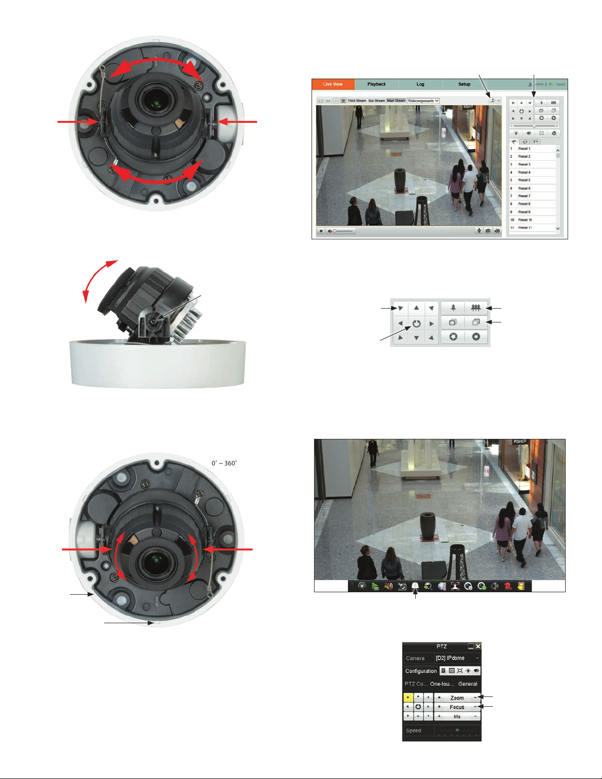
5. In the PTZ Control panel, click the zoom and focus buttons labeled in the graphic above. Verify that
the camera performs as expected. Refer to the Specications section of this document for motion
and zoom ranges.
Step 9. Adjust the camera image for your surveillance target
Use the rmware menus to adjust the brightness, contrast, saturation and sharpness of the video image
if necessary. These settings are initially optimized at the factory and may not need adjustment. When
adjustments are necessary, the paths to the image settings menus are dierent if the camera is installed
as a device on a LAN, or if it is connected to a NVR. Select the installation type below for your camera to
complete this step.
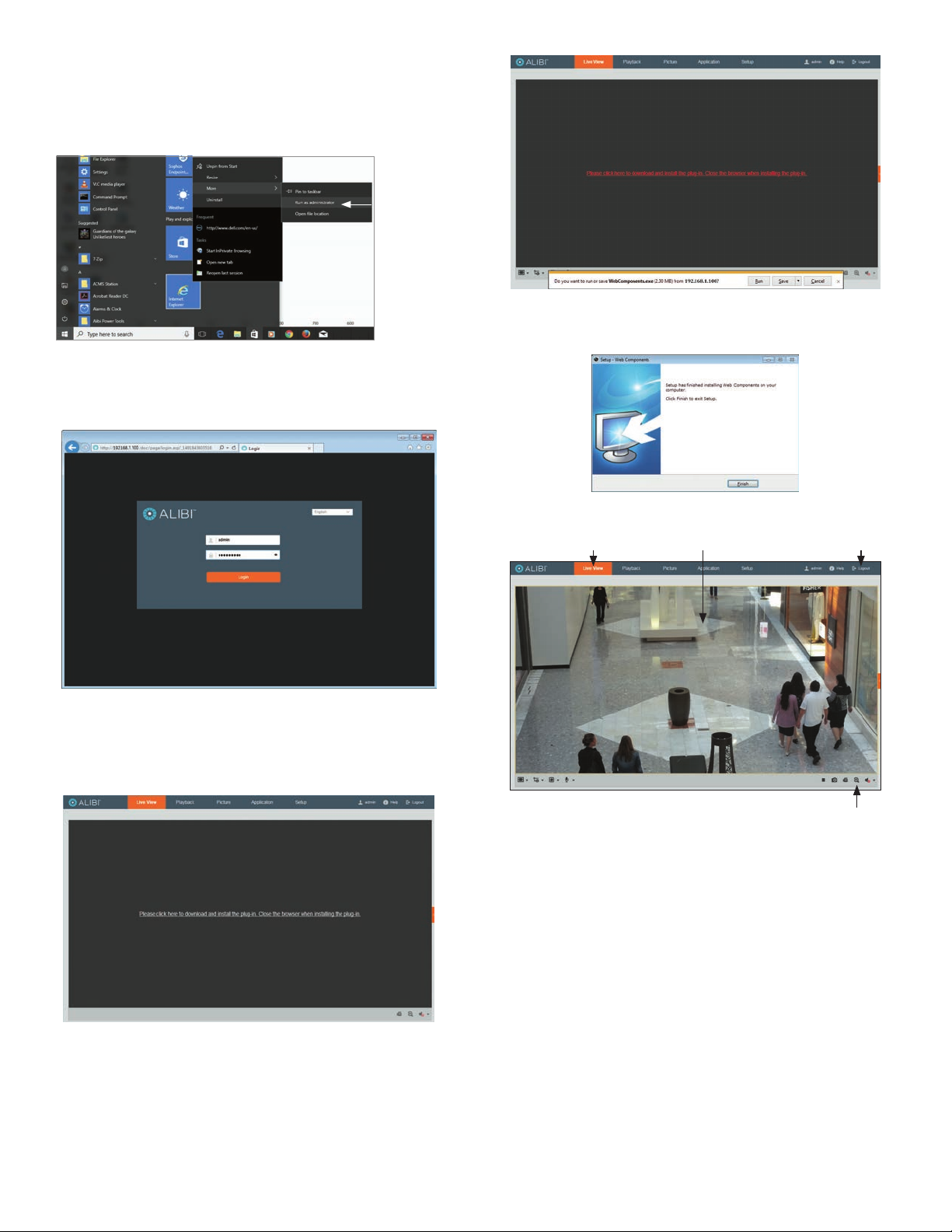
For cameras installed on a LAN
1. If necessary, log into the camera on the LAN with administrative credentials.
2. After adjusting the camera for the a typical eld of view, click the Setup tab, and then click the
Image link in the left frame.
3. Adjust the Brightness Contrast, Saturation and Sharpness of the image. Each parameter can be set to
a level of 0 ~ 100 either by moving the slider or entering the value in the box on the right. The eect
of the adjustment will appear in the Live View image in the menu.
Refer to the rmware user manual for your camera to use the other submenus on this screen.
For cameras connected directly to an NVR
1. Log into the NVR with administrative privileges.
2. Open the rmware Image menu. Go to Menu | Camera Management | Image
3. In the Camera eld drop down list, select the camera you want to congure. In the example above,
[D1]IPCamera 01 is selected.
4. Drag the Brightness, Contrast, Saturation and Hue adjustment markers left or right to perfect
the image from the camera. For some adjustments, you can click the up ( 5)or down ( 6)icons
near the adjustment value (on the right side) to incrementally change the value of those adjustment.
5. Click Apply to save your settings for this camera.
Refer to the rmware user manual for your NVR to use the other submenus on this screen.
NOTE
Cleaning: If cleaning is necessary, use clean cloth with a few drops of ethanol and wipe it gently.
Specications
Camera ALI-NS1132VR
Image Sensor 1/2.8” progressive scan CMOS
Min. Illumination Color: 0.01 Lux @ (F1.2, AGC ON), 0.018 Lux @ (F1.6, AGC ON)
Shutter Speed 1/3 s ~ 1/100, 000 s, supports slow shutter
Slow Shutter Yes
Auto-Iris No
Day &Night IR cut lter
Digital Noise Reduction 3D DNR
WDR 120 dB
Angle Adjustment Pan: 0° ~ 355°, tilt: 0° ~ 70°, rotation: 0° ~ 360°
Lens
Focal Length 2.8 ~ 12 mm
Aperture F1.6
Focus Auto
FOV
Horizontal eld of view: 98° ~ 34°
Vertical eld of view: 52° ~ 19°
Diagonal eld of view: 116° ~ 40°
Lens Mount Φ14
IR
IR Range Up to 100 ft (30 m)
Wavelength 850 nm
Compression Standard
Video Compression Main stream: H.265 / H.264
Sub stream: H.265 / H.264 / MJPEG
H.264 Type Baseline Prole / Main Prole / High Prole
H.264+ Main stream supports
H.265 Type Main Prole
H.265+ Main stream supports
Video Bit Rate 32 Kbps to 8 Mbps
Smart Feature-set
Region of Interest 1 xed region for main stream and sub-stream
Image
Max. Resolution 1920 × 1080
Main Stream
Max. Frame Rate
50 Hz: 25 fps (1920 × 1080, 1280 × 960, 1280 × 720)
60 Hz: 30 fps (1920 × 1080, 1280 × 960, 1280 × 720)
Sub-stream
Max. Frame Rate
50 Hz: 25 fps (640 × 480, 640 × 360, 320 × 240)
60 Hz: 30 fps (640 × 480, 640 × 360, 320 × 240)
Image Enhancement BLC, 3D DNR
Image Setting Saturation, brightness, contrast, sharpness, AGC, white balance adjustable by client software
or web browser
Day/Night Switch Auto, scheduled
Network
Network Storage Supports microSD / SDHC / SDXC card (up to 128GB ), local storage and NAS (NFS,SMB/CIFS),
ANR
Alarm Trigger Motion detection, video tampering alarm, network disconnected, IP address conicted,
illegal login
Protocols TCP/IP, ICMP, HTTP, HTTPS, FTP, DHCP, DNS, DDNS, RTP, RTSP, RTCP, NTP, UPnP, SMTP, IGMP,
802.1X, QoS, IPv6, UDP, Bonjour
General Function One-key reset, anti-icker, heartbeat, mirror, password protection, privacy mask, watermark
API ONVIF Prole S compliant and ONVIF Prole G approved, ISAPI
Simultaneous Live View Up to 6 channels
User/Host Up to 32 users and 3 levels: Administrator, Operator and User
Client Alibi CMS (ACMS), ACMS XP
Web Browser Microsoft Internet Explorer (IE) 8 or later
Interface
Communication Interface 1 × RJ45 10M/100M self-adaptive Ethernet port
Video Output (Without -Z) 1 × Vp-p composite output (75 Ω / BNC)
Reset Button Yes