manuals.online logo
Brands
  1. Home
  2. •
  3. Brands
  4. •
  5. Align
  6. •
  7. Toy
  8. •
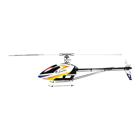
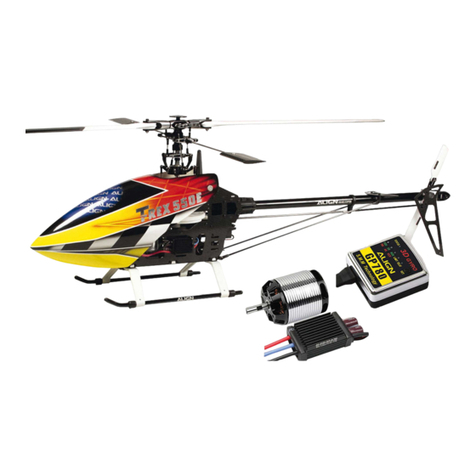
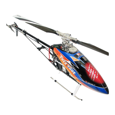
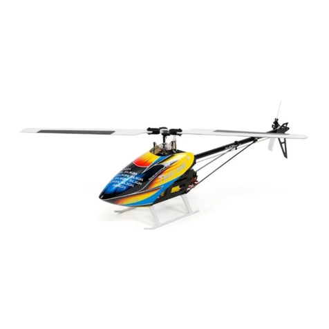
  9. Align Combo T-REX 550E User manual

Align Combo T-REX 550E User manual

I
TREX5STE
IINTRODUCTION
l-2 SAFEW NOTES
Ae)EHFF
3EQUIPMENT
REQUIRED
FOR
ASSEMBLY
Effi&ffi
IPACKAGE
ILTUSTRATION
@#AEE
TSAFETY
CHECK
BEFORE
FTYING
ftfiilqemr
5-t4 ASSEMBLY
SECTION
fiEEiEEE
t5 EqUIPMENT
INSTATLATION
AFEEffiEEE
t0 3G
FLYBARTESS
COT{TROI
UNIT
SENSOR
INSTATI.ATIOI{
Ef,4#^Etrffi#Aft
t0 CANOPYASSEMBTY
#MFAH
t7 ETECTRIC
EQUIPMENT
ITLUSTRATION
€=atffiE#EEEa\
t8SERI/O
ANDTINKAGE
ROD
SETTING
ILI.USTRATION
IETEI8&EFEg
t8ADJUSTMENTS
FORTRO
ANDIAIL
NEUTRAT
SETTING
FSffiEFEFP+UtrffiS
t0 PIrcH ANDTHROTTLE
SETTING
-ffiHREEFEF5ilE
2l-27 3G FLYBARLESS
Ft76O MANUAL
ffi+&'HKffiEEffiEE
2t RCM.BL6(,OM
122OKV
POWER
COITOCATION
REFEREI{CE
FFST:gE#=t
28-30RC€.BUM
BRUSHIEgS
SPEED
COIITROIIER
I]{SIRUCTIOI,I
MATIUAT
trflffiSBEETECB
3t-32 3GFTYBARIESS
FLIGHT
TEST
PROCEDURE
ffifiTlIFIilEF
32-35FLIGHT
ADJUSTMENT
ANDSETTING
ftfi$fFffiEF*,€
303GFLYBARTESS
PREFTIGHT
CHECK
ftfiflilEtr
30SETUP
EXAIIIPLES
rofiFEFArE$ffifi
ll TROUBTESHOOTING
ftffiaifiE#F
NEo&A
ESEAA
^ALIGN
ilfsIRUEIt0il
]ilRltufll
ffHttE=
KXO210027
Pnognalrlfrlable
Flybal.less Systern
Thank
you
forbuying
ALTGN
products.
The
T-REX SSOE
3G is
the
latest
technology
inRotary
RCmodels.
please
read
this
manual
carefuffy
before
assembting
andflying
thenew
T-REX SSOE
gG
helicopter.
we recommend
that
you
keep
thismanual
for
future
reference
regarding
tuning
andmaintenance.
EFffiTiEffinffiEEEFnqem ' Efr;ffH "iEAEHE ni.ilM'rF5
-EF,g
-#
er
4EE€8!
ff -;&
4 )t,a:
. IF' D.{
[E{R
rc,H?ffi
EryBB!
iE
fE+ m
€ I
[rffi
f "
Efrtb RIE
7_ET-'
-#
# U\
# H
,f ffi
BE
=' +Et=
- EHEt0fta,fl
ffiX+E^H
x tr!
Htr
' UEE,f;A=RHE4ffigE= ' D_{,tthA,,A+E
ball A(M3.5x4.5)
5x4
5)
(
o
5x2977mm)
x2
fi't
t[ [
ilU
@
Linkage
uiqlA(fi3
B
tl
B
4mm)x 4
Thrustboaring
rtlE 68(o
6x
o
14x5mm)
x2
/4il
t( il il
\\ /1 tl
.v il
Spindlebearingspacer
ESSESH( o
10x
o
138x0
/A F:l
((( )) |
\\\\ -r/ ll | |
vz Ll
Beadng
$SE(
o
Bx
O't4x4mm)
x
4
Thrust bearing
rt#sR
o6x
o14x5mm
Spindle bearing spacel
ETSSEgH
o
10x
o
13
8x04mm
Linkage
ball
A(M3.5x4.5)
LRTFA(M3
sxa
5)
o
5x29mm
Obverseof bearing
faces
inside,
EOR6CIffiD#E
Apply greaseon thrust bearing.
tffi$saEiHiBE i
Feat|eril|g shdt
FF
o6x6b(g!-Zm
Collar(Copper)
frm€E(ffi)
68x
o l'l sxl 3mm
Metal main rotor housing
GE+re*EEE Apply grease
E-TF;PT
Sod(et screw
HFAAEffi'Ifi
M4x10mm
A[JJ<mg
'+n##i'n"'o
Collar
&SSE8(
o
8x
o115x13mm)
x2
@@
Socket scr6w
HFA^ESRfrft(M4x10mm)x2
I
{o) tl
\-,/ ll
U
Washer
EeS+d(o4xo
12x'1mm)x2
Feathering
shaf
t sleeve
Socket sctew
FffiRIAEffififf
M3xBmm
o3xd48x03mm
lal
EF9OEffiE
O3xO4 8x1 5mm
Metalhead
stoppel
SEMHEffiiJA#
o | ilililt tilmil
Linkagercd(A)
5x6'lmm
x2
A\ [:l
il( ))t tl
\v/Ll
Bearing
*SA(o3xo7x3mm)x4
rA FI
\y hl
Beadng
*SR(Olo5x23mm)x4
@tr
Socket screw
Hffinl^E*4fi{(M2xsmm)
xa
@
@
Sod(et scre$,
EFB^qfijH(M3x12mm)
xl
Socket screw
HEin^8ffiffi(M3)20mm)x1
rA\l
\YI
Washer
+d(O3xO48x03mm)x2
rA\l
vll
Collar
EE*S8ffi E(o 3xo4 8x1smm)
x2
Areadt GsH|Dlad by Facfory.
Bebe iltilg, pba* clEcl( il
the ffi re Eed with glE.
FFE*EEE'E_Aftfitr=
ftEE8F#E6B-LE-F=59.
BallLinks
x4
(usewith link rodA)
EFExa(Pffie561
Metal washout bas6
elGrf,{n€E
Longlinkage ball (M3x3)
UffiFFIF(|13XO\-
64.75ta4.59mmC-=-
Socket collar screw
BEBAETOEHffi
M3x20mm
screw
Mg ltlut
r43SbFXffitE
N
x
|o
dN
(Dx
9,5
Ooi
o@
<R
a3
VS
9:er
Mainshatt
+m
O
6x
O
10x1zmm
Bearing
ssB
O
3xO
7x3mm
Metal washout control afin-
sE#trilEl
Socket screw
HFEAEffitr{
M2x5mm
BE6^Cffitfi
M3x12mm
U}8rr
-q
oloil,&d3rm
Radiusarm
RadiusiEF
Socket screw
FMEAfrHfif
M3x20mm
@)Ih
Sod<et screw
BFn^E#ll{ft(M3x8mm)x1
/Ar t-------f
\Y7 LF-
Soc*et collar screw
HFE^ESBEHffi(M3x20mm)x1
/Ar ql
v H.ll
M3Nut .&-
mmBf;€
xl -ffi*
3GFlybarless
system uses550FLMainshafi
StandardFlybarsystem uses5S0
Mainshaft
3Gft+fsEm*68trs50F1+S
When
tightening
ascrew\
to the wash out base,
please tighten it firmly but
not over tightened. Over
tiqhten will make the screr
tightenwill make
thescr
F-,,tI*o=
*n
*.0.=
o
rr*^*
AEO6J';€2;EEH Efiffi
6
!@Dr
Socket collar screw
HFA1^ESSEffifth(M3x6mm)
x24
@r
Socket button head screur
+HEn^EffitX(M3x6mm)
x2
55H82 55HB2A 55HG
1A
mount
EEtfi x1
Sod<etcolhrscreur
ElriFh^E$0Effi;fifr
M3x6mm Installationlocation (1)
EE&frEi,{n(1) Bearing
MR
o10x619x5mm
Carbon fiber main frames (R/L) Metal bearing holdel
SE+MEEE Sod<etcollar screur
HsehEt=m,fi
HEE6TGg&
1,6mm M3x6mm
Sd*sar€w
ffiAEIEH
i/8(6.m
Sod<et cola screw
ffiBTiEtm€ffi*
lfib(Gmm $
#EEE'fi
Frontframemounting block N
tr*EEEIE
CFBottom
&tE& button head h(et colldscreu,
Emh^*E$Effi*fi
M3x6mm
Framemountangbiock
&E'EiE4
Washer
-ol
o3x08x1mm
Lkid
pipe eindcap
fd*gE
Skid pipe end
frd*ffiER#E
Whentighteninga sclew to a plastic
part,please
tighten it firmly,but not
overtightened,or theywill stilp.
ffiftNffiEPl+ffi#MEH' iHEEIHXED
q' RTiE*0!fl7tq€gs€rr)F5 .
manufactory package,
it the product is already assembled
by Factory, pleas6 ch6ck again if
screws are firmly secured and
appliedwith
some
glue.
FHg{+Uffi€*I[REffi *E' =*Ei[E
aaffifftE6ffigip "
Applya little amountof T43thread
lockwhenfixinga metal
part.
ffifr{iH[fiK fi E1+;E&ffi iQET43
(ffi
ff,p]
@ItI
Socketscrew Washer
HFfi]^ftffi#X(M3x10mm)x4
IFA(o3xoBxlmm)x4
@t
M3 Set screw
M3tEffiJ$fi(M3x4mm)x4
Motor mount
FEBiEB
_qF-eeEe(2}--.-
T
Skid pipe
H*SE
o7
4xogx294mm
Recommendsanding the marked position wathawaterproof abrasive paper(#8OO- | OOO)as
below illustration to avoid the wires ot elesllic parts to be cut.
e;*ttTEEtfrFmE ' qEffiS800-1ooozKBS'IE ' qErt€+EAffi€ffi&gll& '
q
Main
frameassemblY
Point;
Firstdo notfullytighten the screwsof main
frames'
Put
the
main
shaft
through
the
two bearings
and
check
ifthe movements
(up/down)aresmooth' The
bottom bracketmustbefirmlytouchedthe level
table
top (glasssurface);please
keepthe smooth movements
on miin shaft andlevelbottom bracket,then slowly
tightenthe screws.
A correctassembly
canhelpfor the
power
and
flightPerformance.
HBfr!ffif;flilES:
mmmxx*a=e#*' Dr^.+$$Ei#-
m$$Bffi
ffi
-t
lpaUe nm' +EEEffi
'U\FlsUI+Ftr
(Ifi
B+E)
ee Xnt; 6e-R++
tm ;EJtrIEE
ffi+{l FE ffi
4E48ffi
5A
m*r
;rrenums!#E&Hfl
7]lqft
fi'ls6gEffi
E
gtr'
Main
shaft
ES
Presstwo mainframes equally.
+PTEm{ruffiTffi
Main
lrame
sqfriJ&
Glasssurface
frB+6
I
l.
t
55Hz.4
55H
B2A
@lr
Soct(et collat sctew
HF6^E$SEffiftX(M3x6mm)
x2
Nut
ffif Linrase
talt
,l\ Apply
a little amount
otT43
thread
t lockwhenlixingametal
Part.
r n#hHfi!RdElTc-EE.iEE;,lj
(Fft
p:
DS6l OServo
DS6l0EtR#
DSBI
o Servo
D56101dflF38
wServo
spacel
1ETR:B4H
DS620S6rvo
DS620{A[RE8
DSG
FServo
DS6
F{AffiE
Sod(et collar scr€ilt
EFturr*E$SEffit{
M3x6mm
Framesmohting boll
I#9ffi8.
o45xo6x47mm Servo
spacel
€ffi?BEH Linkage
ball B(M2x2.5)
SFB(M2x2
5)
O4
75x12
18mm
-\'.
\
DS6 FServo horn
DS6
FfAffi,E
Nut
ffirtr
M2
-Servo
spacel
4AffiE4H
So<i<et
hrtton hed
Linkageball A(M2x3'5)
IREFA(M2X3
5X
O
a75xB
'18mm)
x2
Linkageball B(M2x2.5)
trFB(M2x2
5)(
o
a75x12
18mm)
x2
Socket button headsell
tappingscrew
#HHfrn-EE&m*#(T2 6x14mm)
x16
-,^U
(9U
M2t{ut
x4
When tightening a sct€w to a Plastic
tightsn il firmly' but not
"/)
,A
Usethe
outer
;Fffi[ffm^tt
3G
Flybarless
systemusesinner
hole(A)
Flybar
system uses
outerhole(B)
3Gft+&rE*ffi.iFffit4tu(A)
€+€HfrffitrH9131(B)
Tailservo mount
EE}BEITEEg
Sodct button headseff
tapping sdeu,
+Htrftn*EEfiffif*
T26x6mm
8
50HTo1
2
Sodret butbn hed self
@grilrg screur
+EF6tiEEffiHfr)<&nm) x2
SE( o4xo
9x4mm)x2
mB( o
12xo18x4mm)x2
Bearing
Frontumbrella
gear
EiJsF&4ffi
021
2x33
6mm
Bealing
*08
o
12xo18x4mm
SodGt button head s6lf
Umbrella
gear
case(L)
&EAEE,g
6
155x6
19x52
5mm
Tailboom mount(R)
EEEE,S(6)
6OONT2A
Bearing
gEa
o
12x
o
18x4mm Socket button head screw
+EffiAAEffi#i
M3xBmm
Metal plate (R)
=FESFg51F!1fi
395x25x5mm
Collar Tail
rotor shaft assembly
ES€EEFS*H
FSEEfEffiF
o
12
4x
o
18x1omn aluminum
standoff
rffil
iA|Bady rsmbbd by F.ctory.
IBeioE flying,pl@* check again il
IsEws aE firmly squEd and
applied with some glu€,
Socket button head
+HEEAEffiffi
M3x6mm
Applyaliltle amountol T43thread
lockwhenfixinga mstal
part,
ffiffitr ftJmSE1+Etrffi EET43
ffi #tP)
o5xo10x4mm
Tail
qearbox
GEgffifEi€ffi
6
4,98x24mm
IF*ffi E=fi H' tr*EGid€ffi ft1.85fr
l
*tE.
@! @!
SB(o12x618x4mm)x2 $SE(o5xoffimm)x2 +
t
55HTs 600NT2C 55HT6
Washel
o3xo
Slide shaft
E+SEE
Metal Tail rotor holdel
GEEM*{E
Socket screw
HF6AEHfifi
M3xBmm
+El
o
3x
o
8x0
6mm
Out
Thrustbearing
rttl$B
6 5x d 'l0x4mm
Tailrotor hub
EffiFT4E
o
10x396mm
Tailrotor holder
EM*{E
Bealing
q$R
O
5x
o10x4mm
Collarscrew
Control
E#ffIEEF
Metal Ttype arm
GFEH#fiJfiHT4E
Collar
Egfr!ffi40€8ff8*g
Metal bdaring holder
EEEHBffIffi*OAEE
Linkageball A(T2.6x3.5)
fiEA(Tz
6x35)
O
475xB18mm
B6aring
*04
o
3x
O
6x2
smm
Collar B
EiEEFffiEB
O
2x
o
3x3mm
CollarA
EEFFffiEA
o
2x
o
3x4mm
Collarscre$,
SEHtr{
M2xBmm
Collal
Effi'T#ffiIEffiE
o3xo4
9x5mm
Washel
o3xO48x03mm
Socket collar screut
HFAAESEffififr
M3x15mm
II /\ CAUTIOT
i:,/!\ * E
When tbhtEr-E a frge ball to a plastic part' please note to usc a little
I Cmly, but not oyer tightened, or th€y wlll stilP.
r*F' Etr4EcAEitEHStzH*Epq' mi6*6!E
l then tigfttEfling r sar to a plastic
paft, pleGe tEfsn I frmtr, hrt not
over tigl#ned, d tlq ril sbip.
fi i*g^4rtrE#- . E€ifr7lE*Hl
q'mSUF8$E/:qg$F#f '
For oliginal ianslectory package,
it the product is .lrra{ttl
by Factory, pl€s€ clFck again if
screws are firrt sEunrd and
rith soD ghF.
3r€tilRE3tB' =#EitE
e6=Frt -
,ll, Applyalittle
amountofT43
thread
t lockwhenlixinga
metal
part.
7 ffiffiiHFBmSE4EtrEitsE-43(FstrF)
@tr
Soal(et screw
BFn/-\EHn(M3x8mm)
x2
a) a)
fl
Bn
I
I
Thrust beailng
trSlSE(o5x$10x4mm)
x2
n
r.)) tl
\-/ L_-l
Beadng
SB(O5xo
10x4mm)x2
fl
(o) tl
\-./ |l
llJashal
+d( o
3x
o
8xO6mm)
x2
@l
il4 S€t screw
tl4rLEE!H;S(M4x4mm)
x1
@
@
Socket collar screw
EF6^E*fi=hffi(M3x'lsmm)
x1
/^l tl
\Y/ U
Washel
+d( O
3x
04 8x03mm)
x2
F-'l
r-) tl
\Y-l U
Bearing
l0E( o3xO6x2smm)
x2
A
t{t DI I I
\V L_-J
Collal
EffiH#HlEStE( o3x
o
4gxsmm)
x'l
@
Collarscrew
SEtRilff(M2x8mm)
x4
OE
GollarA
EiEEFffiEA(
o
2x
O
3x4mm)
x2
ou
Collar
B
EEFFffi*8 (o2x
o
3x3mm)
x2
@
Linkageball A(M2'(3,5)
HFA(T2,6x3
t( o4
75xB18mm)x1
T-.l
r.)) |
\:/ Ll
Bearing
ISts(OOxo10x3mm)x2
o
Slide
shaft
E$SiFE
Xl
/n\ n
VU
Collar
EflBlffi$SEEffiffi4
xI
lfin',
*
(oh oD
ilsD FrD
6r&*,J' tsgax
tu b-he t*f,t
Aim tail rotor hub al the concave of tail rotol
shaft and fix it,please apply a little glue on
the set screw.
EffigT4Effi+E&mSUAJitffi t' E-re#tEffi#fl
LW"
After complete the tait rotor assembly, Ploase check il it rotates smoothly.
(lf not, pleaseproperlyadiust the part gap')
EreHfiEfiE
*+FT{AEBffi
=6
Effi
H{tr€A )EEGOEZiIIFEEJEHEA
C+'I+ffiffi)
10
When assembling into the tail boom,
pleaseapply some oil on the sudaoe,
to make it smooth during the
assembling and keep ltvertlcal with
the torque tube for smooth rotation.
ffi.zrE€BFi' tiE*eFES ' D-rIER!,EE
EE+IINEFA$SRF*E .AEEBEAffiffi
.thetail boom,
please
aimat the
fixinghole
O
5.
F EE6E)t'F3,
{d+E€ o5EEtb
oo l|ic torque tube, avoid CAglue adhering to the dust
beari$g stuct- Whcn.ssenbling into the tail boom, please apply some
press the hold€r astoUretaalboom horizontally.
' *JEcAi5€aA&EE=m=ilaA+tU ' ffi,^.EEhF' E€E mAgffiflA
I EE
TF'FEl=a.
SpraySiliconeoil insidethetail boom
EAtrBFM
Torque
tube bearing
holder
EEASRE
oI 4x7 5xl 0mm
%**w
HEFn^ESFHtfi(M3x22mm)
Apply
a
little
amountoff43 thread
lock
whenfixingametal
part,
fr
*SffiN$THFtrffiETT43
(ffi
*1P)
M3 Nut
M3EbFiffiIE
Socketscrew
tsFftrr-Effi#
M3xBmm
Sod<et
button
hed sct6r,
trFfuAEMEffi{#
Mgxl6mm
J ../ Torquetube
E€DSF
Tail control guide
EEfiJFEEE Sod(et sefftapping scrEur"\
BFn/GErflffit{ \\
T3t0mm 3K CF Horizontal stabilizer
3K&Sd+F 3K CFTailblade
3KTfr&EM*
Ruddrer contol rod \
EIfEif,IEF
Tdlbdn
EEt
461m
Tailboom brace
E9€ffi
So.iGt sdf tapping
gg&\8Effi,lfi
T3x1omm Washer
OBxO3xlmm
stabilizel mount
iTYEEETg
Verticalstabilizer
mount
EEEEE
3K CFVerticalstabilizel
3K6ftS4ER
55HT3A
@r
Socket scire$,
tsFfil-/ iq$Rifi(M3x8mm)
x 4
AIF
vlH
M3 Nut
mm#SFfE
x4
@t@
Socket selttapping screw
HFEnEEEffi ftX(T3x1omm)
x2
@ lmnm
Socket self tapping screw
HFAAEEIITffiftfI
(T3x20mm)
x2
+d(O8xO3x1mm)x2
@r
So.*et b|rbr hed sar€w
+gFEL'GgHm)rl
@ ftnrurD
ffietffinheadself
tapping scrsu
+EFEnq 3nf SCI3xi
omm)x'l
2
@Dr
Sod(et screw
EFfrl7-\E+Rfiff
(M3x1omm)
x2
5OHT4A 55HB2B Applyalittleamountol
T43thread
lock
whenlixingametal
part,
H#{H[I!FSEi*M=FtriEEI4
3
(Rffi
F)
When tight6ning a sc]Ew to a plastic
part, pleaso tighten it firmly, but not
ovel or they will
For original manufactory packagel
if the product is already assembled
by Factory, pleas6 check again it
screws are firmly secured and
appliedwithsome
glue.
Hfr*i+UMESfi1RE€*B' tr*Ere
ffiAffiXhE6HRIF "
Socket button headsell tapping screw
+tsFRAABXHffi
T3x12mm
,/,/
'/,/
*
Tailboom fixing screw
E€EEffifft
Socket screw Washer
BFEAEHfr* +d
M3x10mm O8xo3xlmm
55HB2A
@mm
M3 Set screw
l13tHfi#(M3x1smm)
x1
55HB2B
55HB3
Linkagerod (D)
Approx.SOmm
x 3
EF(D)fi!50mm
x3 I,r M3
Mg Nut
M3F'#ffi|tr
Main ddve gear set
/
A
I
Socketcollarscrew
BEFftr-Eft€ffi**
M3x20mm
@@
Socket button head self
tapping sclew
+BFts^EE4*#h(T3x6mm)x2
mEETGElqfi,H(I3x7mm)xs
One-uay bealing
FElt( olao 18x16nm)xl
Washer
FtsSETd( o115x
o1$O8mm)xl
@tF
Sod<et collar screw
ErFE^ES€H#(M3x20mm)xl
E
[3ffiF,HExj
Standard
Equipment
:
Main
shaft
spacer(0.5)
Mainshaft
spacer(0.3)
FEffi ' .gssH(os)
o
10lxo
14x0
smm
,2
"o
When tighiening a scr€w to a Plastic
part, please tighten it firmly, but not
ortheywill strip.
E4I'+H
' i6gETrH*E[
]EEE+TTiF5
"
over
original manufactory package,
if the product is already assembled
by Factory, please check again if
screws are firmly Secuted and
ied with some glue.
Ei+sff E*!0REE*ffi ' EE#Eiftr
One-way
bearingshaft
f,lain gear case
+'EADE
M4 Set screw
M4tESR#{(M4x4mm)
x'l
@m
For original Banqtactory
if the product is alraady assembled
by Factort, pleae check again it
screus arc firmht socutod and
rillr som6 Fff,HMEiffi
55FLH1A *
M4Ntn --P
M4E#ffi|tr
Socket screw
HFhn*Effif#
520 Carbon
fiberblade
520ffiF-m*
Motol pinion
gear167
FE6m 16r Socket bttton
self tapping l
#HFhn-.EE
T3x6mm
M4 Set scfeuv
M4lti9ffiti*
M4x4mm
/lD Apgt | ru rilt ofTrlllrhned
rI7 locirf.rfr-rxtdFrt
r tSEtrtstIFEEEtf+lCtt)
wlEn tEl*niE. scrrlD a plastic
part, pleesetbhbn it frmly, but rEt
mr qtE ril
55H25
re
fdt ltr-----------r
\y Lt-
Socketcollarscfew
/A\ FI
vHl
M4 Nut
MaFD#ffi€
x2
For motor fixing
,EiT6Effififi
After assembling
the motor piniongearand maindrivegear,
the horizontal
distancemust bewithin I mm andkeepthe gearmeshata proper distance.
F E ffim!{l:EHGfEt # rF
ti EESE4 Ef iE1
mm'
ft Rt+mF [I e € E H F€
fiE
.
Hook and LooPTaPe(hooked)
Use attached Hoop and Loop Tape' tape
the Hoop side (hooked) on the battery
mountingplate and the Loop side (fuzzy)
on the Uittery to fix the battery in ordel
to preventanY
sliP.
iil
H
F
H
EH
HHE
w
H'fi
E
ffii*"'R
c
EIffi'6^ffi
Hook and LooP Tape(tuzzy)
FfiD,5Effi
Use Adhesive foam or Hoop & Loop tape
to fix.
L){Effig6E4Ef[il688'
NOTE: When installing the sPeed
controller,please keep a distance at
least 5cm from the receiver to avoid
anY
inlerference.
*c#ru'*qE+'fi*q'R
++
='J5
crnl,xt
Hook and l-oop TaPe
EEffiF
ESCinstal lation location
ESCA=fi
il
Flvbarless
Sensor
*+etE,gEE5
Senbormounting
foam
mffiEBEE)E+E
lt
When
connecting
thewire
harness
between
control
boxandsensor,
push
the
connector
alltheway
in,
andmake
sure
theconnector
latch
engages
theunit
witha "click"sound.
Theconnection
needs
to have
sufficient
slack
toavoid
vibrationsinduced
disconnects.
Disconnects
during
flight
willresult
inloss
ofcontrol
andcrash
of
the
model.
*t+ffiEi+ Bg&
G--t
Directional
Arrow $ensor
mustbeinstalled
witharrow
pointing
to
ffOnt orfeaf ofthehelicopter
as
s-hownii
diagram,lgvgl, anU
awayfrom
vibration
sources.
lfexcessvibration
fromhelicopter
frame
isaffectino
flybarless
sensors
causinginsiability,
twosensor -
foams
canbeused
to mount
thesensor.
lf problem
persists,
attempts
shouldbemade
to
eliminate
vibration
source,
or reduceheadspeed.
RrS€BEfiEH#gffi Eais*ffi
€ret*Feffi E' Z(+rEfiKFaffi
1trEEE
' trSffiFSF.
ffiG*drgFrgtrffi *{Ftfltl'
EFtr,ft
ll6HE' qmffiEEtsTE,F6fiS
2H)E+FmR
'Efi*&= '#ffiE &EfFDi*trEIE,iE.EE*tff
.
Canopy
{SFE x1
When
assembling
thecanopy
to theunit,
please
cqlnpbtelywedge
intothegroove
ofthebottom
plate.
HFEA*FEEF .=iE* +€Effi f}EEfu .
:e
55HC1
Socketbutton head
selftapping screw
+HFAAEETTffi#N
I JXbmm
Har
+t<
sE
EI
R6-
H3
tr91
o
6
o
ElIU'
Eo
#5
&i@
x!ro
il l{
la
'5;I
I :-
g
-ir
=
!
7
{
U'
6
m
z
=
I
c,
t
o
z
z
o
o
o
z
z
m
o
-{
o
z.
r
c
v,
-{
n
{
o
z
DI
=
Lla
I 5e t
I F3 3
I g?f
I erEg
h";;t9;E
IIRJEEl
l-@=o
g)m
lI o-
-<
s3
*r
96)
Fi$
fi6fr
d
R
Fil
ffi
E
m
m
o
o
o
P.
g
E
a
r@
H
ffi
H
o
o
o
q!
5i
oE
3C
=.
o
o
€
o
-i l
*.{-,i c
..vg 4
- ^> g
= \ l!
G!q
s@
G'{
trH
f<
&
&
c€
!
m
U
tr
lFlo=
RO
F3
tre
H6=
"-5
@
l'
I
F
6
GiA I
Ps fi
;r; o
F=
l:1 tn
t .E_r =
ffi9
'6'
x8.
,Ul
+I
t
UI
11
l.
{
o
o
Rn
.-zc\
-u --Rt
--A\
iFT
=O
=3
o
JREFEfSJffiEflETSffiffi Positions
ofCH2
.
CHOare
exchangeable,
After
assembling
as
photo(Note:Set
the
transmitter
under
CCPM120
degrees
mode),
pull
throtfle
stick
(pitch)
upward.
lf
oneswashplate
servo
(or
twoservos)
moves
downward,
adjust
reverse
switch
(REV)
onthe
transmitter
to
make
itmoves
upward.
lfthree
servomove
downward,
adjust
thetravelvalue
(+-)
of
SWASH
CH6
onthe
transmitter
tomake
them
move
upward.
When
theactions
of
Aileron
and
Elevator
areopposite,
adjust
travelvalues
of
SWASH
CH2and
CH3.
To
setthis option isto turn onthetransmitter
andconnectto BECpower.
TLtrilEFPFf
g#EdEB'
I*TBEC€)HE|]EiEfrH{T
"
FUTABA/HITEC
Transmifter/ServoFUTABA/HlTEcWgegWmmnne*mm Positions
ofCH1
'CH6areexchangeable,
After
assembling
as
phQ:[o
(Note:Set
the
transmitter
under
CCPM
1.@bgrees mode),
puil
throtfle
stick
(pitch)
ffione swashplate
servo
1or
twoservo@ffifu ownward,
adjust
reverse
switchffiffithe transmitter
tomake
#'E+?ffi
fiEEEFIE
Recommend
to
transmitter and
neutralsetting.
Lock
t$i
rad
lock ffiutionrnixing(RyMx) mode.
on thetransmitter,
thensetthegain
switchon the
aboutTo"/o'
andafter
transmitter
sefting,
connect
to BEc power
to work on tail
Note : When ail rudder
stick andthe helicopter.Then
waitfor 3seconds,
make
tailservoarmandtail
mustbecorrectly
fixedaboutinthe middle
ofthetravet
oftailrotorshaftfor standard
servo at a right
neukal setting.
[zffiEEE'e ffi-dE#EEffi&$$)8f+8il
' tr*r#Bd8Bt8!ffitrffi88-rE,pEffiEDatrEErt
, mtrilft! i0%E6, gftq]€silefttr
ts3fjBuffiffiffiE{aEfolffFHffilEEid[F€3f0Fie0"'Effis4ffitfiHFElEEtsEE$sfiEf0+F€{rE,F0hH#E+u
6t*t8ECt*r&€E 46TffiHffi
)+H'€BABI
q++ ^
HEAD
LOCK
DIRECTION
SETTING
OFGYRO
Tocheckthe headlock direction
of gyro isto movethetail
counterclockwise
andthetail servo hornwill betrimmed
clockwise. lf it trims inthe reverse
direction,
please
switch
the gyro to"REVERSE".
F3ffi
ffi
$HEE H
iE#,' H+EE"$[ & F iFffi
q, E {d
NF
EffiIF
ts'E{4
J-lillryyilg direction rrim direction
for
€f,ESEH _"1
tail
servohorn.
E.E,BRHtrEfiFI
Aftersetting Helad
Lockmode,
correctsefting positionof tail servo andtail
pitch
assembly
isasphoto.
If
the
tailpitch
aCsembly
isnot
attheneutral
position,
please
adjust
thelength
of rudder
control
rod
totrim.
[effi{*$HEffiElEBF
3B
trE Pitch#
ffil]ilEEffi
EE{t Ei" EE p
itch#ffilflB
* E+ F ;€
ffi
CE
FtrIIiEFs!Ftr*{EE "
GENERAL
FLIGHT
_ffiftfiE'T
Stict po"ition
it HoveringlThrottle
60%
/Pitch+5'
EEFS/SP960%/Pitch+5"
at lowlThrottle
GENERAL
FLIGHT
-ilsflfiEfr
tl
1234
Tffi Crrve{Simple
Aerobatic
=+fl':Ff,fiP3ffiffi
t_
5
Flight)
ffin :1,Pitch
range
:Approx.i15 degrees. .-
11
l\ S'ia" ,:
Z.lfthe pitchis set too high,it will resultin shorter
fight dlrttir
andPoor
motorPerformance'
S.Setting
thethrottleto provide
a higher
speedis pr€frra* lo
increasing
the Pitch
too high.
1 ffiffE(Pitch)ffi{r{=f0
t1s"
2.
EAEf;EEEEE'
g€1{97r'8ftfi0+F5Ef{4'
3 ATIEFD-{mE€it8!-dEbil' EDtffiEEAEtmAE'
tll
12345
Tffi Curve(3D
Flight)
!=-ffEi*P5Sffi
Throftle
sP9 Pitch
ffiffE
5100%High
sPeed
100%€iE +10'
485%
360%Hovering
60%Fffi +5'
210%
10%
Lowspeed
0%{EiF o"--2'
'*il
ol.e-2, 3pFLidHT
Stick
position
atlodThrottle100%/Pitch-1
EE{Eift/;tsP31
00%/Pitch-1
0'-1
2'
19
@
@
@
B
@
@
@
@
tffi;l
[?s0-7001
@
@
@
@
3-axis
gyroscopic
flybarlesssystemtosimulatethestability
of mechanical
flybarsystem,
yetatthesame
time
achieving
agile3D
performance.
3$S
ggffi
Effi+ gF-#ffi ' q&ffi €+sH ffiffi
s!
ffi
EtE' FEF)E 8!3
D'ir6g
"
UtilizesSiliconMicro
Machine
(SMM)
sensors
forexcellentstability.
*HS.M.M.
Silicon
MicroMachinefi
fEff
ffi3*,R€M{+ff!ffi
E,lt "
l2 bitprocessors
providing
ultrahigh
resolution,resulting
inhighly
precise
controls
*ffi 12fi7.8838' ffila*ffi+f
tr' #ffi|JffiHffi+ "
Softwareupgradable
throughPGinterfaceadapter
(sold
separately)
Effiq#ffi8;t{LtfH ' qiEi,EEffib?F*filffi (€ffib?Effi ) "
Simplisticsehtp
process
withouttheneedofexternal
devices.
Setupisdone
through5stepsand2sensitivity
Ruddersebrob identicalto GP780
qvro.
minimizinq
learninqcurve.
EEEF4=&'Tffi'.E' RHfi{EDW: ffiIEffitrEBCE[q=FTFfEFEE
' EffiAEfOGPTSOffiIE
' &EffF't+ "
Flybarlessslstemdramaticallyimproves3D
power
output
andefficiency.
resu.lling
!nreducedfuelorelectricityconsumption.
+ € = Xt-' q X Ei
Ft
{E3
Dt g {f f f F^g
E )Hf,' f HEF HF i B!
f 7r
fi HE F lDHF€ P m
q'En "
HQhtysensitive
gyroscopic
sensons
combinedwithadvancedcontrol
detection'routine
providing
higherhoveringand
aerobatic
stabilitythanotherflybarlesssystem.
€ tr tr EE E H:8& ft iE
E ff8;E
=i' q F {*n - nE+ € H* tffi
F {+
8!
65ffi& f, ffiffiE'lS "
Suitabb
forallCCPM
and
mechanicalmixingsystem.
EtrFf Ettfrt2FJffiil =lEBFStcCPMXffi&15fft
++ffi *ffi .
Cornaptiblewith helicopterof allsizesfrom T-Rex250to T-Rex
700.
3G
Flybarbss€=ilffi
ffi
Ei.X{Ai4EF#FX4EF#r-REX250-T-REX700 "
lnnovative
pibh gauge
asanaidtofacilitate
pitch
adjustments.
€!tff a-SEEEH:*' €D-{tHffiH+eiHXfft ZffiEEE,UTJ
.
Highframeratesignaloutputforfasterandhigher
precision
servo
response.
8ff9tr6#iltF' @EtF:gB!trffi8r0ffi+ . nE "
CapabletDoperatebetween3Vto8.4Vcompatible
withhigh
voltage
EtrEE3v-8.1v' qEH€E{ABESB
.
Small
fooQrint,
lightweight,minimalistsand
reliable
design.
€Edr ' EEE ' E=*ffitsqF ' €HR#9la=tt€98!ft11#ffi .
Directmode
for
neutral
#ftfi{=F+fi$E
Rudder gyro Eil,
reversesettings
RudderServoReverse
settings
EBEFUffiEJERHEftE
Aileron
endpointssettings
EIJHffi{EEEE
Rudderendpointssettings
FlffifiE,3?E
Aileronreversesettings
EIID-FA4A
ts!=frxtqilt
Servofiamerabsefrings DigitaUAnalog
servosettings
(1520lls
and760ps) gtj.&Ftr{ABEEBaq€
FE1520us&EE 760us
{ABF38EEE
|;:ffi :,,PRE-cHEcK:fi
t€d,ffi,iff
ffi*
Rudderservodelay,and
helicoptersizesettings
EffEEIEERA4\E'I#+Ffi
Whileusing3G
FBL
system,
besuretoturnoffthe
followingfunctionsinthetransmitter
Effi C#SE IiEEIT T T'II D ffiFFjMWF4$ffi
SwashRing rt LinkageCompensation * Swash
Mix
* Acceleration
*
*
l.Connectthereceiver
andservostothe
flybarless
control
unitasper
diagram
found
onpage
17.
2.Digitalservos
must
beusedoncyclictoavoiddamagetoservos.
Retommendedservospec:minirirumspeedO.1Ose-c/60,
torque12kg.cmorhigher.
3.Transmittertrimtabs
must
becenteredbefore
enteringthesetup
process.
ltcanbemoved
aftersetup
iscompletetotrimtheheli.
4.3GFlybarlesscontainstwoindependent
power
circuitstoenabletheuse
ofdifferentvoltage sourcesthroughthereceive(For
example,7.4Vtothe
cyclicservos,5Vtothe
gyro
andrudder
servo).lfthereis
only
one7.4V
power
source,a stepdown
voltageregulatorisrequired
(available
separately)toprevent
rudder
servo from
burningout
|lffi To
prevent
voltageinstability,
do notusestepdown
voltageregulatorifpower
source
is
alreadyat5V.
ll+E_E i, Please
consult
your
servo
manualsandensure
proper
voltage
aresuppliedtothe servos.
5When
the3G
flybarless
system
isinstalledforthefirsttime,afewsimplesetupstepsand
flytestsneedtobeperformed
intheflybarless
sefup
m'ode.
These
steps
ne'edtobep-erformed
onlyduringinitialsetup,anddoes
irotneeci
toberepeatedfor
subse
quenf
flights.Just
poweir
upthesystem
normally,checktheproper
servooperations,and
fly. Theinitial
setup
procedure
onlyneedto be repeatedaftersoftwareupgrade,
pitch
rangereset,
orsubtrimsareaddedinthetransmitter.
I).',u
I tgEr&3t&{dBFt8fiEffiz\HffiiEE
(;EAffiH
17
F )
2
+-_"__wU:FA#SinEffi8*
' aFtJgEFtr{dtFAt}FEE
.
eE*iBffi
:spo.10fl)/60"
lrn ,nz:izrrj.cm-Mi
3.iE ilE8SlIy\€ffStr#389!9Nffi
SBEB€,
ftllB+E&ffi
ft {rilnffi Sffi
ffi
4,3GF3GFlvbarlessflffltF8*ffii
€FBFFtrH+P_trflEt: 9E€CEg-EiFr@s=ry_E4eSr]-pd.1F:tr64:Ii,€F_(
Fti[ ,+?ffi@
ER#Efr,7.4v,/W4R{*
.EDE{dBF
38ft1H5v)
"H&&€*€FEF7.4v
' p,.eut'muEntsv€EiH;'EJREfrifidBFEHa**iIEmm
) fiEf;REzEili+r ,D-{pElrEf,EEEFBstr€EiE,a=mtree,
4v/wwffi. EEE{dEF
838tr€EiE,a-rtutrEg
"
rlAuFE,.lgE#ffi
ffi#fi
#5?',iEGF*'ffi
HFgffi
#ff
uh#H**u*ff
Affi,**
5
H-4qS:3G Flvbarressffi*&i'**ffiB$
' 4,FE7iffi*&i_H_4884
' iEfiffitrEU
ryF.*.fl.8*ryEF{4_,.ftFr'ffipIJi{F,E^y,&EEil ,RpEHp€&
ffi6EnE38e{r
Ere{aE0qftl]
'ml:eem+irt
' eaffiriEEE-d#E#6ffift-GiiGim:)#;
tiiag'Xilce;iEef,i,,+d-*iffia*
_
F.!IB4.R
LE
SS
S
yS
TEMI
N
I
Tt
ALSrETU
pSTE
p
g,t 5F
fi *trffi !EE
1.DlR:
Direct
mode
to
bypass
gyro
for
mechaniciiiiavet
and
neutral
point
setup
ornfidf
fiEF+fi$&EEil I :
Enter
theDIR
settings #Hi.i- m DtReE -
uo
o
QE o,
%trw Press
andhold
the
SET
butonwhile
powering
up
thereceiver.
Release
thebutton
when
LED
1-5begin
tocyi.te.
The-Dlitgreen
LED
wiiifr-g-htu-p
indicatingrthegyro
has
been
-bypassed
for
neukar
a-norecniniil ii"uer
range
setup.
mF-sEr
Eae .
$rg€EEtE+EEEgESc,
$E=LED1-5(DtR-A.REv)€llEF
FP__{E{Tfl&FE€ .'DrR'EEFE ,EUiCaeo
plyoar
less#*ffi1ilE-ia,i,
ESC BATT
function
check tH2: ++&fE$Effi
In
case
ofinconect
servomovement
o-rro-
movement
atatt,
ptease -
9!9.gf,fgr
P_r9ter
connection
betwqgn
3GflybarbCJc6nnecii5n
toiervos,
as\'vell
as
proper
setup
on
transmitter.
EtA iE#*,1EEEEE
ffi
AfF' =F€3G F
I
yba
r
Iess
l-dEEE$iltih#filEfritx&E
ESAAEEEEffi"
movements
forPlT.
AlL.and
ELE
inouts.
PTT
. AIL .ELEE5Effi "
Pay
extra
attention
tothese
setup
steps. Incorrect
neutrar
points
wiil-
affectflight
stability,
andworse
lead
toloss
ofcontrol.
4Dffi#ffiF-EEE
' E+Uff7FEffi ' T.{EtrgftfHE,lt ,EtrHE
EFTT'46!'EF
"
Adjust
subtrims
on
transmitter
so
servo
horn
/riT\
r-t-i1-T
Iitl
I-LU
- _'ffi
+ 12"
pitch
range
112'llEESnEE
Adjust
themaximumcollective
pitch
usingthehansmitter'sswashplate
mixingfunction
(pitch
swashAFR).Recommended
pitch
ranget12",
maximum
pitch
rangeforadvanced
pilot
shall
not
exceed
+14".
e#ffiEE-688t 12" HEmffiETtBiE+ 14" hpR'
Donotadjustindividualservos
endpointsthrough
the
servoATV/AFR
function,
useonly
swashplate
mixing
adjustments.Shouldany
changes
madetotheendpointsorsubtrims
on
thetransmitter
in
the
future,theflybarlesssystem
initialsetupmustbe
performed
again.
ccPMfiffiffigfrf=Ets' FtrEEE*Swasht9ffiEElL* (Pitch
swashAFR
) ffi
g' n^ffi#lEBlB[F#mArvfifEG "
ffiiaEH# 8!
n #fl
ffit0E-EE, tb\Ee*n
#EF tyb
a
rtessE
rF
-aR
E .
Maximum
cyclic
pitch
setup:
With
movethetransmitteraileronstick
all
inSWASH until
+12'pitch
range
+
12'1EFSREE
.5 : Cvclic pitch setup &Eifi.lr5
rGftffiEEEQE
function
(AlL
swashAFR).Do
notadjust
throughtheservoAVAFR function.
madetotheendpointsorsubtrimsonthetransmitter
lrlesssysteminitialsetupmustbe
performed
again.
fE,E. ffi'4kfrre.#6ff{eEm€qF ' MAE*fiE
While
using3G
FBL
system,
be
suretoturnoffthefollowing
functionsin
thetransmitter
EH3GftffiEIIEETIHT'!IDS
FFmna$fr
* SwashRing
* Miring
* SwashMix
* LinkageCompensation
* Acceleration
to helicopterbody,
and
adjust
theAILmixing
mixingtype
recognition
andelevator
endpointsetup
:
E.LIM+
?llE E#E,F,ftF.Gfi EI&'Ef, il :
Whilekeepingswashplateleveland
main
pitch
at
zero
degrees,
press
theSETbuttontoregister
the
neutral
point
andenterE.LIM
setup
mode.TheE.LIMLEDwilllitupafter
DIR
turnsoff.
Ri$_l-?ffihzj<+
.ftHEtrfr+trglt ffiT ,t*€rffT,sEt,ffiD|RE#8tr
ffi' E.LIM
lHilg€Hru'E 'E.LIMIfEfrUfffEE'-#GE-I
"
throttlestick
position
wheremain
pitch
is0degreemustbe
ined
throughthissetup
process.
t+,FE6t+reHEHOHE!{VE'
AqE€fl
With
allchannelsstationary,move
thetransmitter
elevatorstickforward,
andthenbacktocenter
position.
Thiscompletes
theswashplatemixing
typerecognization
process.
The
control
unitwilldetermine
theCCPM
mixingratio
ortraditionalmechanicalmixing
maximum
elevator
endpoints.
TSEEST#EES#4&frJE(=N9FUE.fOffi
EA{F)'ETg+EffTEFtrtr
+P€IUE'
ftFIftEilAE"
-
:
-
\r---t? degreemustbe
@Throttle
stickmust
bemaintaii
*FSEFEE
aoELE
--
(::- \-
r---__-}l
-\o
Hode
,LJ
E
E
E
E
3.E.REV
elevatorreverse
setupmode
:
E.REVfi
FiMlgiltriEE FI
&iEEfi :
S'u*ut F
in
diagram,andcheckif
wrong
direction,movethe
transmitter
changes
color,and
re-check
the
=E 'E.
REV
IIEiffi
[effi{SEtrE"E?EElt'
' eRrt6;=5 .ffE-t-#E l-EfrElP";ffiffiEiIhqt
tr*--
iffi -:-?510!
lEiEE
EEAEffi .
{IIR
+ ?ffi €€=€#' =.
Eg'IEff Effi
f€
d[ry
STATUS
EffiE&, EA
re-#+?Eg=-6E==C=
Helicopter
tilting
direction
#H{trf$EE
#ffitrFfj.+EE OO
lLj, iEtEv
=2c
I
SET
4.A.LIM
aileronendpoints
setup:
A.LIMEIEfiEIEQEEil: Press
theSETbutton
toenterA.LlM
setuomode.TheA.LIM LEDwill
lit
upafterE.REVtums
off. Wtthall
channelsstationary,move
the
aileronstick
to
theright.
andthenback
tocenter
position.
This
completes
theaileronendpoint
setup
prDcess.
The
controlunit
will
determine
the
maximum
aileronendooints
'*=&T"S EI"E' =AE€TiE7\'A. LIMEIJHffi
E€'-#E&il' IIbB+E.
REVtr
[if 'A.LIMEE'ff*Eeg56gJE 'n6t&f]EFE+ ' fFIiJt&i
-#E' *3G Flybarlessffi9Ej=qEfrE.
Thethrottlestick
position
wheremain
pitch
is0degreemustbe
maintained
throughthissefup
process.
I-
I- i-_ F
E
-
-
!-
)tsP5'€Ffr
EDS-ffi
FEtrotrmfiE' Z<qEEgl
Throttle
stickmust
bemaintained,
TF9EFE'E
AIL

Other manuals for Combo T-REX 550E

2

Other Align Toy manuals

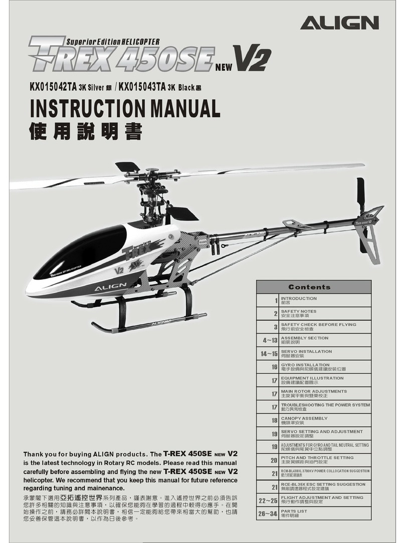
Align T-Rex 450SE new V2 User manual

Align

Align T-Rex 450SE new V2 User manual

Align Trex 250 SE KX019005T User manual

Align

Align Trex 250 SE KX019005T User manual

Align Trex SE User manual

Align

Align Trex SE User manual

Align Trex 250 Combo KX019001TA User manual

Align

Align Trex 250 Combo KX019001TA User manual

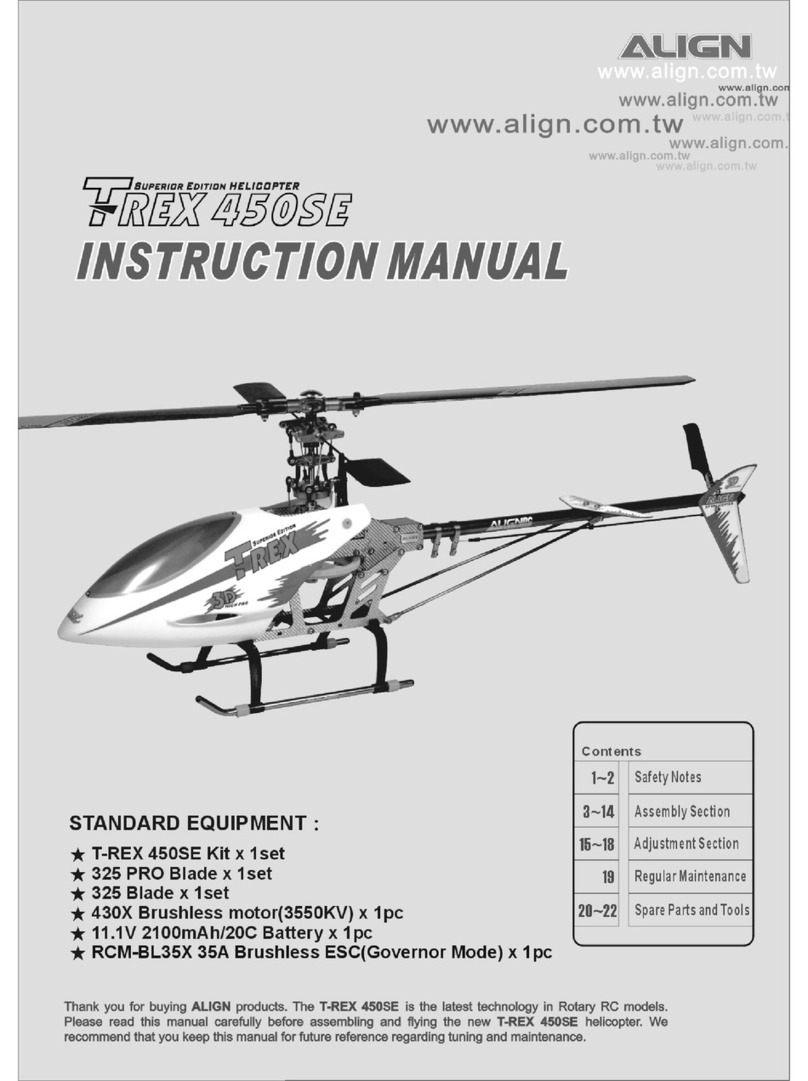
Align T-rex 450SE KX015042TA 3K User manual

Align

Align T-rex 450SE KX015042TA 3K User manual

Align TREX 700E V2 User manual

Align

Align TREX 700E V2 User manual

Align Trex 450XL CCPM User manual

Align

Align Trex 450XL CCPM User manual

Align Trex 250 Pro Super Combo KX0190010T User manual

Align

Align Trex 250 Pro Super Combo KX0190010T User manual

Align T-REX500 User manual

Align

Align T-REX500 User manual

Align Trex 150 SFC RH15E01XT User manual

Align

Align Trex 150 SFC RH15E01XT User manual

Align Trex 700 Electric conversion Instruction Manual

Align

Align Trex 700 Electric conversion Instruction Manual

Align T-REX 450PRO User manual

Align

Align T-REX 450PRO User manual

Align Combo T-REX 550E User manual

Align

Align Combo T-REX 550E User manual

Align Trex 500ESP User manual

Align

Align Trex 500ESP User manual

Align Trex 450 Plus User manual

Align

Align Trex 450 Plus User manual

Align T-Rex 500CF User manual

Align

Align T-Rex 500CF User manual

Align T-Rex 450SE V2 User manual

Align

Align T-Rex 450SE V2 User manual

Align Trex 700 Electric conversion User manual
Align

Align Trex 700 Electric conversion User manual

Align T-REX 450X User manual

Align

Align T-REX 450X User manual

Align nitro trex 600 KX0160NPNT User manual

Align

Align nitro trex 600 KX0160NPNT User manual

Align T-Rex 450 SE User manual

Align

Align T-Rex 450 SE User manual

Align T-REX 600ESP User manual

Align

Align T-REX 600ESP User manual

Align Super Combo T-Rex 700E F3C KX018E06T User manual

Align

Align Super Combo T-Rex 700E F3C KX018E06T User manual

Align T-REX 600 CF User manual

Align

Align T-REX 600 CF User manual

Popular Toy manuals by other brands

V-tech SWITCH&GO VELOCIRAPTOR RACE CAR instruction manual

V-tech

V-tech SWITCH&GO VELOCIRAPTOR RACE CAR instruction manual

Pro Boat Miss Elam owner's manual

Pro Boat

Pro Boat Miss Elam owner's manual

Pro Boat Pro Boat Miss LLumar owner's manual

Pro Boat

Pro Boat Pro Boat Miss LLumar owner's manual

KID Trax Dodge Charger owner's manual

KID Trax

KID Trax Dodge Charger owner's manual

Step 2 SPRINGTIME WHEELBARROW 4006 quick start guide

Step 2

Step 2 SPRINGTIME WHEELBARROW 4006 quick start guide

V-tech MobiGo  Game Storage user manual

V-tech

V-tech MobiGo Game Storage user manual

ThinkGizmos TG663 user manual

ThinkGizmos

ThinkGizmos TG663 user manual

KNEX Pac-Man 64547 Assembly instructions

KNEX

KNEX Pac-Man 64547 Assembly instructions

BSD-Racing BT1004 manual

BSD-Racing

BSD-Racing BT1004 manual

Roc Hobby 1100MM NXT operating manual

Roc Hobby

Roc Hobby 1100MM NXT operating manual

SWorkz S35-4E instruction manual

SWorkz

SWorkz S35-4E instruction manual

V-tech Two Smart Laptop user manual

V-tech

V-tech Two Smart Laptop user manual

Phase3 EF-16 Assembly instructions

Phase3

Phase3 EF-16 Assembly instructions

V-tech 3-in-1 Sports Centre Parents' guide

V-tech

V-tech 3-in-1 Sports Centre Parents' guide

Step 2 Mr. Monster Truck Assembly instructions

Step 2

Step 2 Mr. Monster Truck Assembly instructions

Step 2 Write Desk 797500 quick start guide

Step 2

Step 2 Write Desk 797500 quick start guide

PLAYTIVE JUNIOR HA-2195 Instructions for use

PLAYTIVE JUNIOR

PLAYTIVE JUNIOR HA-2195 Instructions for use

Spinmaster PAW PATROL DINO VOLCANO PLAYSET instructions

Spinmaster

Spinmaster PAW PATROL DINO VOLCANO PLAYSET instructions

manuals.online logo
manuals.online logoBrands
  • About & Mission
  • Contact us
  • Privacy Policy
  • Terms and Conditions

Copyright 2025 Manuals.Online. All Rights Reserved.