Operation and Maintenance Manual
8
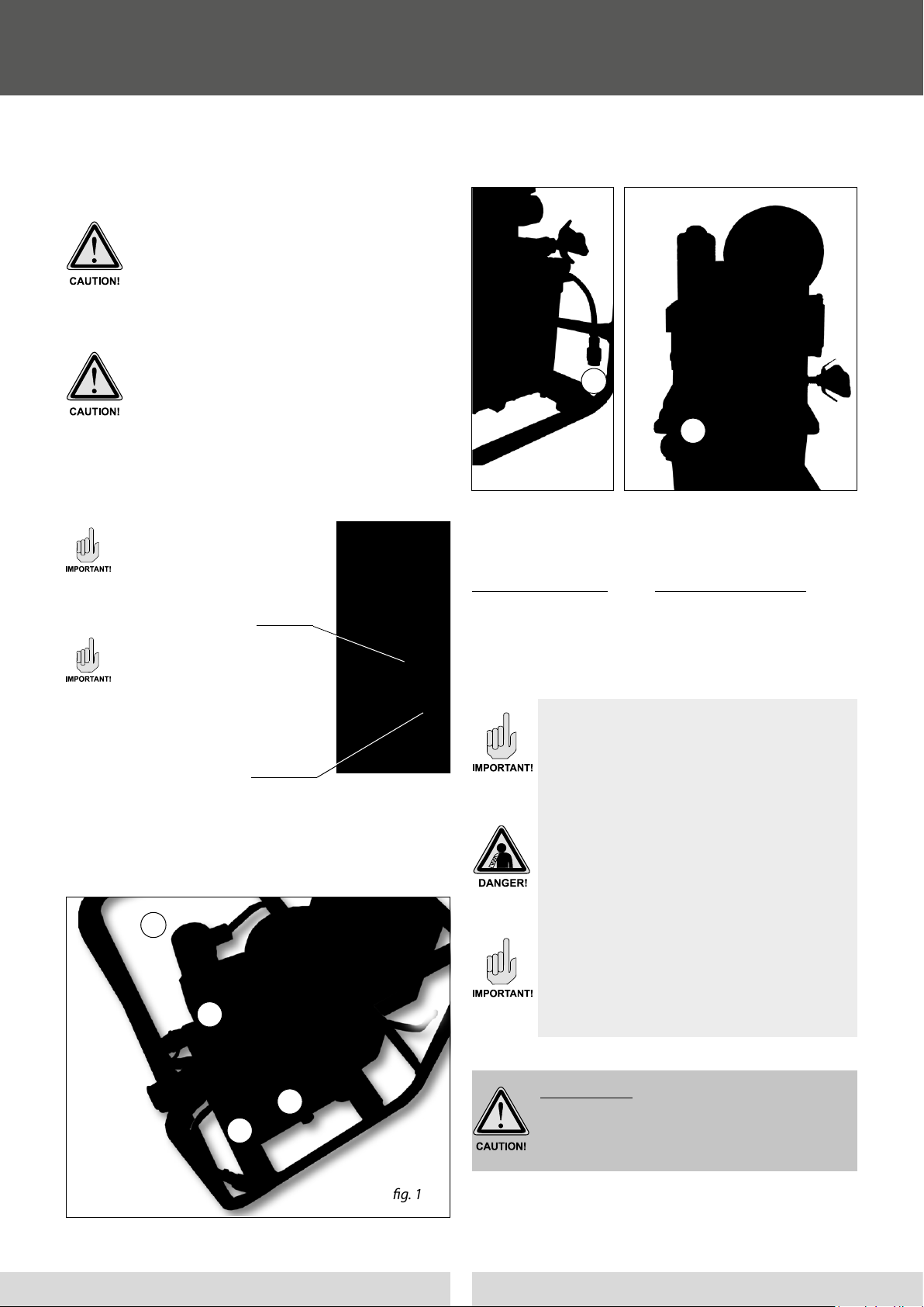
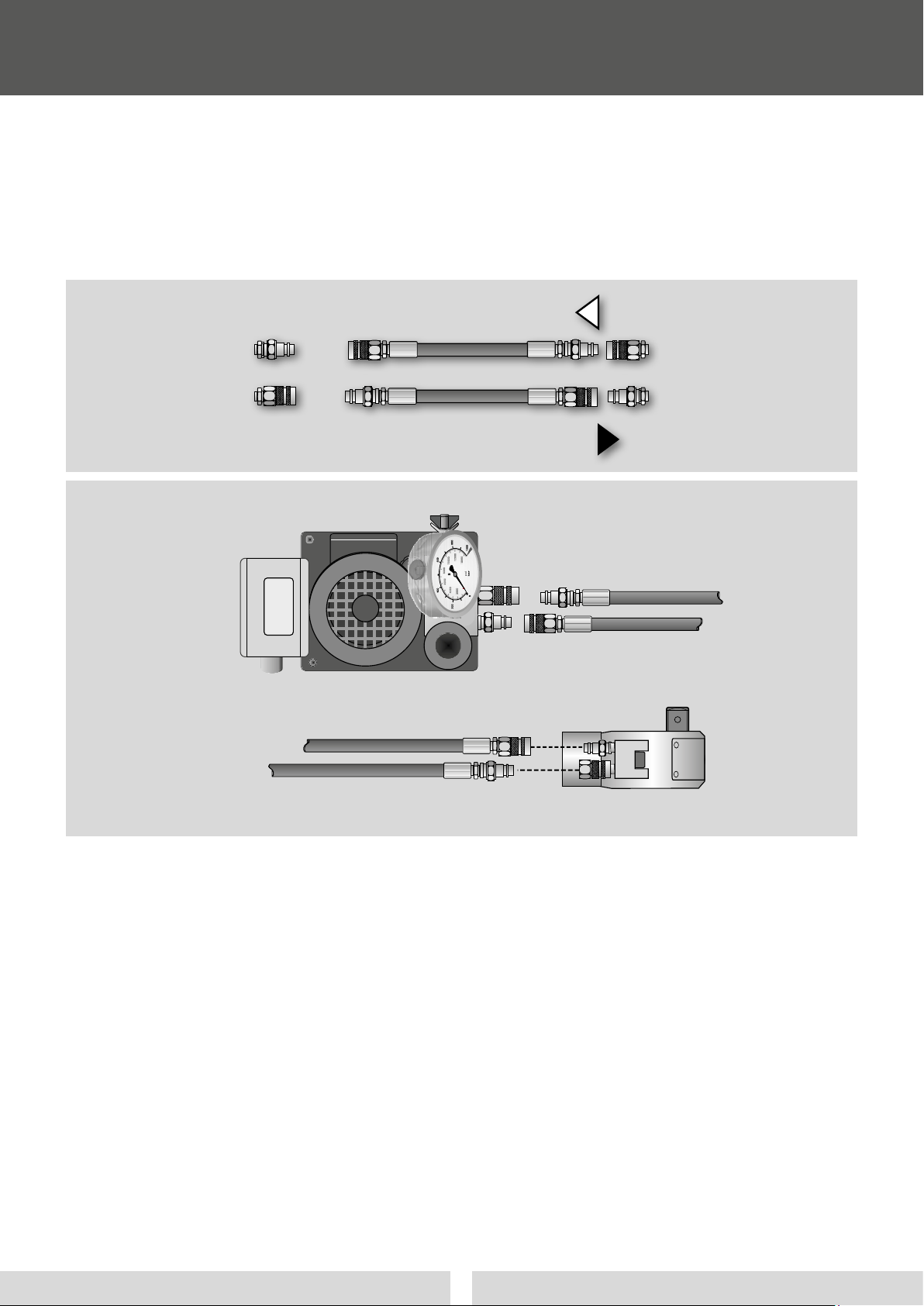
4.3 Change of direction of rotation / wrench change
Switch o the pump by pressing the black button
(2), see remote control Fig. 2, page 7.
Relieve the pressure on the LEVA
Hydraulic Pump !
Press the manual override
on the top of the solenoid valve.
Disconnect the LEVA Hydraulic pump from the
power supply (pull the plug).
Adjust the hydraulic wrench according to the de-
sired direction of rotation and connect it to the
pump (LOOSEN or TIGHTEN screw connection, see
the instructions for use of the hydraulic wrench).
Reconnect the LEVA Hydraulic Pump to the power
supply. Press the white button (1) on the remote
control to switch it on, Fig. 2, page 7.
When changing a torque wrench, a torque setting accord-
ing to point. 4.1, page 7 is to be achieved.
5. Functional Test
5.1 Visual inspection
Check the connections see point 9,
Fig. 6a / b, page 10 - correct connection diagrams.
5.2 Check for leaks and contamination
The high pressure hoses and all couplings, ttings
and connections must be checked for integrity
and cleaned if necessary.
Dirt particles in the hydraulic system lead to mal-
functions and breakdowns. Check the hydraulic
parts for leaks, defective components must be
replaced professionally.
5.3 Compliance with time limits
To ensure torque precision, an accuracy check of
the pressure gauge must be carried out with the
help of a test pressure gauge for a given occasion,
but no later than annually.
The oil level and oil quality must be checked regu-
larly. In the case of frequent use, we recommend
changing the oil annually (for oil type, see techni-
cal data).
Authorized personnel must also have the LEVA
Hydraulic Pump checked for electrical safety and
mechanical defects at least once a year. With high
loads / stress / operating hours at shorter intervals.
5.4 Requirements for hydraulic hoses
For safety reasons, replace all hydraulic hoses with
normal requirements after 5 years at the latest
(additionally a maximum of 2 years storage time).
With increased requirements (multi-shift opera-
tion, short cycle times, hand-held tools) after only
2 years. Additional regulations from the legislator
(DIN 20 066 / BGR 237) must be observed.
The operating and service requirements specied
in these instructions for use must be observed.
6. After use
After the work has been completed, depressurize the
LEVA Hydraulic Pump and disconnect the pump
from the power supply.
Remove hydraulic hoses and multipliers and keep
all components dry and clean.
(See also the following descriptions)
6.1 Storage
Keep the LEVA Hydraulic Pump dry and clean in
the alkitronic® transport case or in another seal-
able container.
Moisture leads to oxidation on the housing as well
as on internal parts. Consequences can include
malfunctions and further damage.
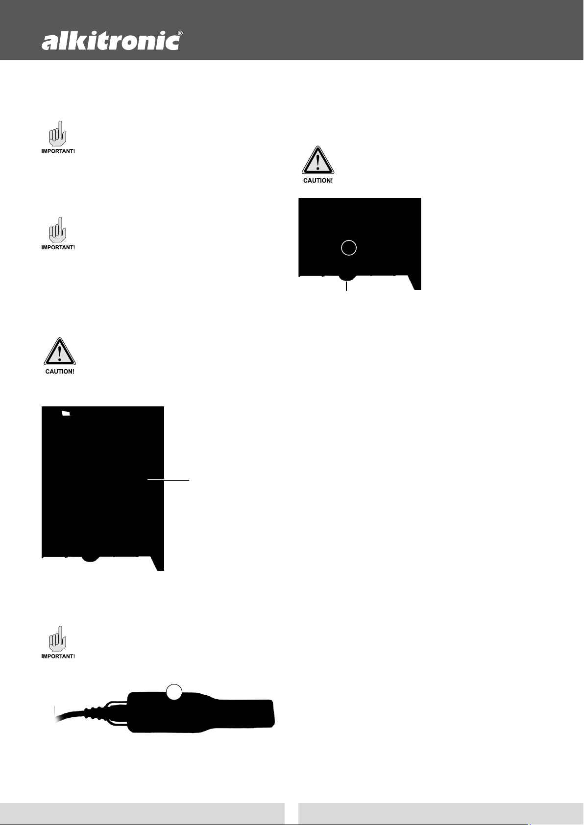
Hydraulic hoses
When storing, make sure that the hydraulic
hoses are removed and the ends of the hoses
and connecting parts (couplings / nipples) are
closed with the protective caps.
Store in a cool, dry and low-dust condition.
Avoid direct sunlight and UV radiation, ozone-
forming lighting xtures (e.g. uorescent light
sources, mercury vapor lamps) and storage
temperatures below -10 °C.
Hydraulic hoses must not come into contact
with acids, alkali, solvents.
Store tension-free and lying at. When stored
in rings, the minimum bending radius specied
by the manufacturer must not be undercut
•
•
•
•
•
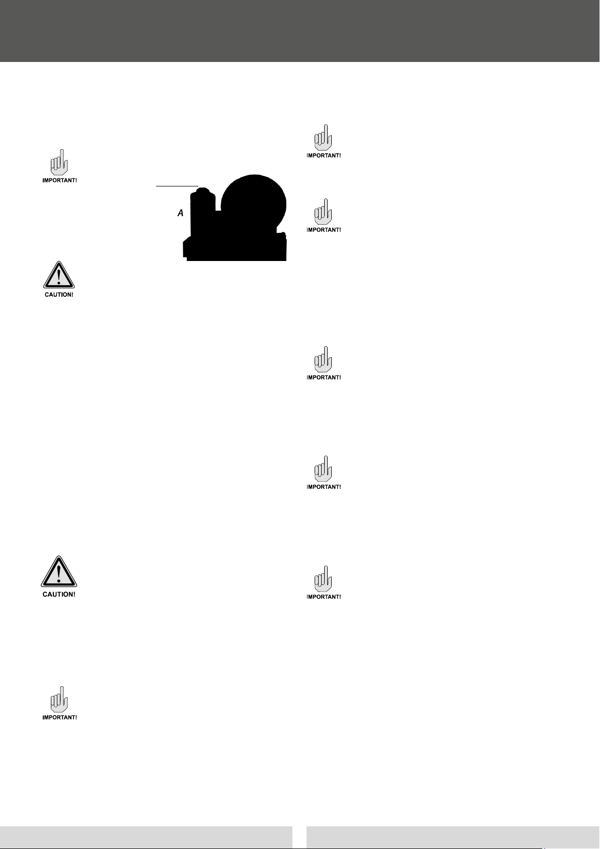
Magnetic
valve