Alldaq ADQ-SCU 2.2 User manual

ADQ-SCU 2.2 Manual
Rev. 1.0 EN
ALLDAQ signal conditioning unit baseboard,
optional powerboard and relay board

2 3
Pin assignment ADQ-SCU 2.2 Rev. 1.0 Pin assignment ADQ-SCU 2.2 Rev. 1.0
Imprint
Manual ADQ-SCU 2.2
Rev. 1.0 EN
Date: 03.07.2020
Manufacturer and Support
ALLNET® and ALLDAQ® are registered trademarks of ALLNET® GmbH Computersysteme. For questions,
problems and product information please contact the manufacturer directly:
ALLNET®GmbH Computersysteme
Division ALLDAQ
Maistrasse 2
D-82110 Germering
Support
E-Mail: suppor[email protected]
Phone: +49 (0)89 894 222 – 474
Fax: +49 (0)89 894 222 – 33
Internet: www.alldaq.com/support
© Copyright 2020 ALLNET GmbH Computersysteme. All rights reserved.
All information contained in this manual has been compiled with the greatest care and to the best of
our knowledge. Nevertheless, errors cannot be completely ruled out. Specications and contents of this
manual are subject to change without notice.
We are always grateful for the notication of any errors.
Mentioned trademarks are registered trademarks of the respective companies.

4 5
Pin assignment ADQ-SCU 2.2 Rev. 1.0 Pin assignment ADQ-SCU 2.2 Rev. 1.0
3.4.11 Audio output (STB19) ������������������������������������������������ 31
3.4.12 Measuring signal tap (STB20..21) �������������������������������������� 31
3.4.13 Analoger AI-GND (AGND) STB1 ��������������������������������������� 32
3.4.14 68-pin VHDCI sockets from/to ADQ-34x �������������������������������� 33
3.5 Powerboard (ADQ-SCU-PB) ����������������������������������������������� 34
3.5.1 Pin connector strip JB1 -> J1 ������������������������������������������ 34
3.5.2 High current supply switchable (ST1..8) ��������������������������������� 35
3.5.3 Sense connection (ST9)����������������������������������������������� 35
3.5.4 Supply switchable (ST10, ST11) ���������������������������������������� 36
3.5.5 Sense connection (ST12)���������������������������������������������� 36
3.6 Relay board (ADQ-SCU-RB) ������������������������������������������� 37
3.6.1 Pin connector strip JB2 -> JR2 ����������������������������������������� 37
3.6.2 Changeover relay (STR1..4) ������������������������������������������� 38
3.7 Customer-specic plug-in boards (CB1..3)����������������������������������� 39
4. ADQ-SCU 2.2 BB App ������������������������������������������������� 41
5. Monitoring stage with headphone amplier ����������������������������� 43
6. Specications ������������������������������������������������������� 45
7. Annex ������������������������������������������������������������� 55
7.1 Supplies ��������������������������������������������������������������� 55
7.1.1 Cables������������������������������������������������������������� 55
7.2 Manufacturer and Support ������������������������������������������� 55
7.3 Important notes �������������������������������������������������������� 56
7.3.1 Packaging Ordinance ������������������������������������������������ 56
7.3.2 Recycling advice and RoHS conformity ��������������������������������� 56
7.3.3 CE Identication ���������������������������������������������������� 56
7.3.4 Warranty ���������������������������������������������������������� 56
Content
1. Introduction ��������������������������������������������������������� 7
1.1 Scope of delivery �������������������������������������������������������� 7
1.2 Safety instructions ������������������������������������������������������� 7
1.3 Installation and assembly site ��������������������������������������������� 8
1.4 Brief description��������������������������������������������������������� 9
2. Overview of the system����������������������������������������������� 10
2.1 Block diagram���������������������������������������������������������� 10
2.2 Baseboard ADQ-SCU-BB�������������������������������������������������� 11
2.3 Powerboard ADQ-SCU-PB-50 ��������������������������������������������� 12
2.4 Relay board ADQ-SCU-RB ������������������������������������������������ 13
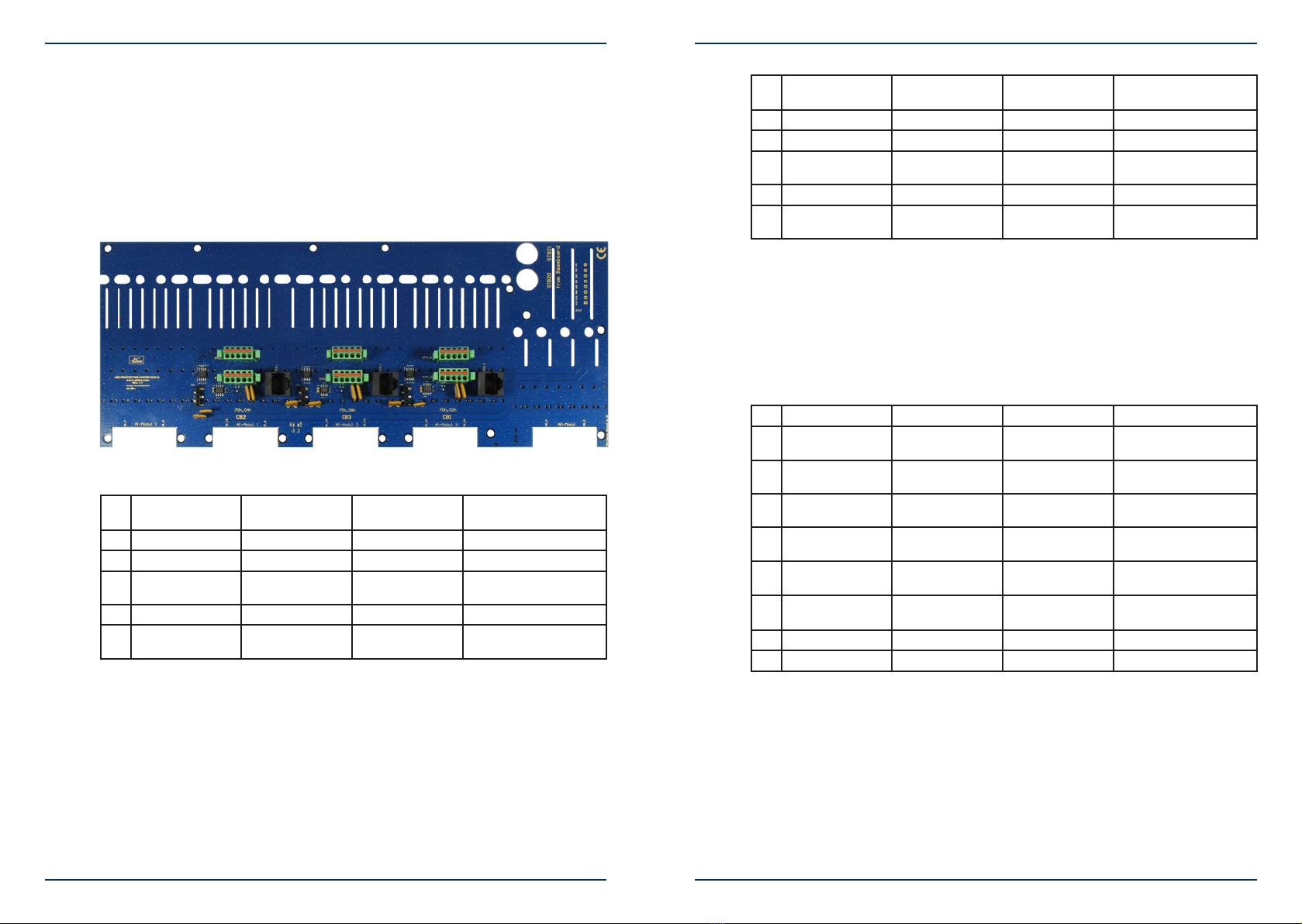
2.5 ADQ-PROTECTION-COVER ������������������������������������������������ 14
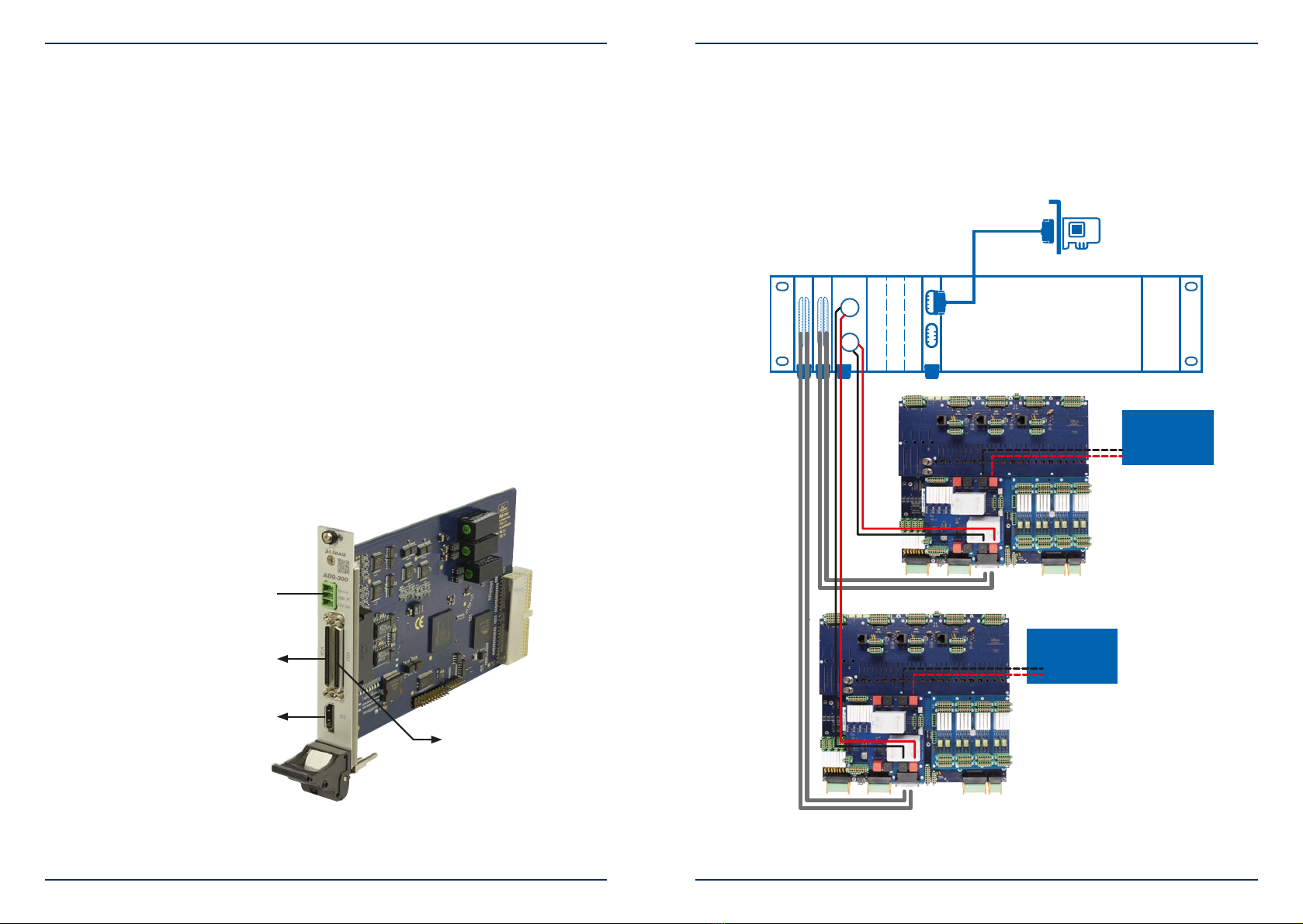
2.6 Multifunction card ADQ-348 ���������������������������������������������� 16
2.7 Example system conguration �������������������������������������������� 17
3. Pin assignments ����������������������������������������������������� 18
3.1 Position of the connectors ����������������������������������������������� 18
3.2 Prexes of the connector designations ������������������������������������� 19
3.3 Overview of the connector types ������������������������������������������ 19
3.3.1 Type Würth �������������������������������������������������������� 19
3.3.2 Type Phoenix Contact������������������������������������������������ 19
3.3.3 Type Pin plug ������������������������������������������������������� 20
3.3.4 Type Würth �������������������������������������������������������� 20
3.3.5 Mating connector for Würth connectors �������������������������������� 20
3.3.6 Mating connector for Phoenix connectors������������������������������� 21
3.4 Baseboard (ADQ-SCU-BB) ������������������������������������������������ 22
3.4.1 Analog input section (STBA1..4/STBB1..4) ������������������������������� 22
3.4.2 Analog output section (STBA5/STBB5) ���������������������������������� 23
3.4.3 Digital I/O section (STB6) ��������������������������������������������� 24
3.4.4 External trigger inputs for AI/AO part (STB8) ���������������������������� 24
3.4.5 Counter, ignition signal & temperature alarm (STB9) ���������������������� 25
3.4.6 Pin assignment (STB10�A) �������������������������������������������� 26
3.4.7 Special functions (STB10�B)������������������������������������������� 26
3.4.8 Switchable auxiliary voltages (STB11..14 > STB15) ������������������������ 27
3.4.9 Supply for baseboard (STB16) ����������������������������������������� 29
3.4.10 HDMI connector for special functions (STB18)���������������������������� 29

6 Introduction 7
Pin assignment ADQ-SCU 2.2 Rev. 1.0 Pin assignment ADQ-SCU 2.2 Rev. 1.0 Introduction
1. Introduction
Please check the packaging and contents for damage and completeness before commissioning.
Should any defects occur, please inform us immediately.
• Does anything on the packaging indicate that anything was damaged during transport?
• Are there any signs of use on the device?
Under no circumstances may you operate the device if it is damaged. If in doubt, contact our
technical service department.
Please read - before installing and programming the device - this manual carefully!
1.1 Scope of delivery
• ALLDAQ Baseboard ADQ-SCU-BB for signal conditioning unit
• ALLDAQ ADQ-SCU-BTB adapter
• 2 x 68-pin VHDCI cable (male-male), double shielded, cables twisted in pairs, length: 1.8 m
(ADQ-CR-VHDCI-68M/68M-1.8m), part no.: 146813 (2 x)
Optional:
• Plug-on board ALLDAQ Powerboard ADQ-SCU-PB
• Plug-on board ALLDAQ relay board ADQ-SCU-RB
• 2 x 68-pin VHDCI cable (male-male), double shielded, cables twisted in pairs, length: 1.2 m
(ADQ-CR-VHDCI-68M/68M-1.2m), item no.: 150597 (2 x)
• HDMI cable, length: 1 m (ADQ-CR-HDMI-MM-1m), item no.: 127015
1.2 Safety instructions
Be sure to observe the following instructions:
• Avoid touching cables and connectors
• Never expose the device to direct sunlight during operation.
• Never operate the device near heat sources.
• Protect the device from moisture, dust, liquids and vapours.
• Do not use the device in damp rooms and under no circumstances in potentially explosive
areas.
• Repairs may only be carried out by trained, authorised personnel.
• When commissioning the instrument, please observe the installation regulations and all
relevant standards (including VDE standards), especially when operating with voltages
higher than 42 V.

8 Introduction Introduction 9
Introduction Pin assignment ADQ-SCU 2.2 Rev. 1.0 Pin assignment ADQ-SCU 2.2 Rev. 1.0 Introduction
• We recommend to always connect unused inputs to the corresponding reference ground to
avoid crosstalk between the input channels.
• Always disconnect the eld wiring of the analog and digital inputs/outputs from the signal
conditioning unit (ADQ-SCU incl. plug-in boards) as well as the connection to the ADQ-348
before connecting or disconnecting the power supply of the signal conditioning unit.
• Make sure that no static discharge can occur through the device when handling the card.
Follow standard ESD protection measures.
• Never connect the devices to live parts, especially not to mains voltage.
• Precautions to avoid unpredictable misuse must be taken by the user.
ALLNET® GmbH Computersysteme is not liable for improper use and resulting damage.
1.3 Installation and assembly site
The signal conditioning unit (ADQ-SCU incl. plug-in boards) is intended for installation in
measuring and test systems by qualied personnel. The relevant installation regulations and
standards must be observed.
The ADQ-SCU may only be used in dry rooms. Ensure sufcient heat dissipation. Ensure that the
connecting cables are securely attached. The installation must be carried out in such a way that
the cables are not under tension, otherwise they may become loose.
1.4 Brief description
The ALLDAQ ADQ-SCU signal conditioning unit was developed to optimally adapt a large num-
ber of analog and digital inputs/outputs to the requirements of a complex, automated measure-
ment and test system. Signals are acquired and generated synchronously via the multifunctional
ALLDAQ ADQ-348 measurement and control card, which simultaneously controls the ADQ-SCU
via I2C bus.
Important features:
• Analysis of audio signals of different levels
• Adjustable input coupling (AC/DC), digital lters, gain and attenuation
• Measurement and mathematical evaluation of relevant parameters
• Monitoring level for listening to all audio channels
• Generation of audio signals for stimulation of power ampliers
• Switch supply voltages via relay, optional: ADQ-RB-16/8
• Switch currents up to 50 A (100 VDC) via relay, optional: ADQ-SCU-PB-50
• e.g. connect the supply voltage to the DUT
• Customer-specic extensions via plug-in modules
• Simple control via ALLDAQ driver system
• API for easy integration into your application
• Optimized for operation with the isolated ADQ-348 DAQ and control card

10 Overview of the system Overview of the system 11
Overview of the system Pin assignment ADQ-SCU 2.2 Rev. 1.0 Pin assignment ADQ-SCU 2.2 Rev. 1.0 Overview of the system
2. Overview of the system
2.1 Block diagram
AI_0..7± AI_0..7+
AI_8..15±
AI_16..23±
AI_24..31±
AI_8..15+
AI_16..24+
AI_25..31+
Daisy chain connection from drawer to drawer
Input Coupling
DC
AC
max. ±51.2V
Attenuator
G = 0 dB/-27,95 dB
Adaption
G = +0,0 dB/
+46,03 dB
diff. s.e.
Mezzanine Board
Mezzanine Board
Mezzanine Board
Mezzanine Board
Amplifier
G = +0 dB
Analog Muxer
8:1
8:1
2x 8pin (STBA1/STBB1)
L
R
VHDCI (STB_VB)
Input Coupling
DC
AC
max. ±51.2V
Attenuator
G = 0 dB/-27,95 dB
Adaption
G = +0,0 dB/
+46,03 dB
diff. s.e.
Amplifier
G = +0 dB
Analog Muxer
8:1
8:1
2x8 pin (STBA2/STBB2)
Input Coupling
DC
AC
max. ±51.2V
Attenuator
G = 0 dB/-27,95 dB
Adaption
G = +0,0 dB/
+46,03 dB
diff. s.e.
Amplifier
G = +0 dB
Analog Muxer
8:1
8:1
2x8 pin (STBA3/STBB3)
Input Coupling
DC
AC
max. ±51.2V
Attenuator
G = 0 dB/-27,95 dB
Adaption
G = +0,0 dB/
+46,03 dB
diff. s.e.
Amplifier
G = +0 dB
Analog Muxer
8:1
8:1
2x8 pin (STBA4/STBB4)
ALLDAQ Signal Condition Unit (SCU)
Base board (ADQ-SCU-BB), power board (ADQ-SCU-PB-50)
and relay board (ADQ-SCU-RB)
L
R
L
R
L
R
VHDCI (STB_VB)
TRIG_AI_x
±2.56V
Amplifier
G = 0 dB/+18,06dB
Amplifier
G = 0 dB/+18,06dB
AO_0+
±10 mA
s.e.
diff.
Mute
s.e.
diff.
Mute
AO_A+
AO_A-
AO_B+
AO_B-
±10,24 V
Amplifier
G = 0 dB/+18,06dB
Amplifier
G = 0 dB/+18,06dB
AO_1+
s.e.
diff.
Mute
s.e.
diff.
Mute
AO_C+
AO_C-
AO_D+
AO_D-
±10,24 V
Amplifier
G = 0 dB/+18,06dB
Amplifier
G = 0 dB/+18,06dB
AO_2+
s.e.
diff.
Mute
s.e.
diff.
Mute
AO_E+
AO_E-
AO_F+
AO_F-
±10,24 V
Amplifier
G = 0 dB/+18,06dB
Amplifier
G = 0 dB/+18,06dB
AO_3+
s.e.
diff.
Mute
s.e.
diff.
Mute
AO_G+
AO_G-
AO_H+
AO_H-
2x8 pin (STBA5/STBB5)
2x5 pin (STB8)
±20.48 V
Trigger
AI Section
TRIG_AO_x
Trigger
AO Section
DI_x
1x10 pin (STB6)
VHDCI (STB_VA)
1x10 pin (STB6)
DO_x
Digital Out
Isolated on ADQ-344
CNT_OUT
Ignition Strobe
from ADQ-344 counter
HDMI (STB18)
20 pin (STB9)
PWM_OUT
PWM Out
from ADQ-344
Incremental
Encoder
from/to ADQ-344
Digital In
Isolated on ADQ-344
20 pin (STB9)
Temperature
Monitoring
EEPROM for customer specific data
Power (STB14)
Power Switch 4
4 A
4 A
Power (STB13)
Power Switch 3
4 A
4 A
Power (STB12)
Power Switch 2
4 A
4 A
Power (STB11)
Power Switch 1
4 A
4 A
2x20 pin (STB15)
5pin IDC (JB3)
+5 V
+12 V
GND
5pin IDC (JB4)
+5 V
+12 V
GND
8 pin (ST10) 2pin
(ST12)
4pin
(ST9)
8pin (ST11)
ST1..4
ST5..8
Power Board
(125 x 135 mm)
U1_IN
GND1_IN
U0_IN
GND0_IN
GND_PC
+5 V
+12 V
GND_PC
I2C
+5 V
+12 V
GND
I2C
5pin IDC (JB5)
+5 V
+12 V
GND
Analog Output Section
Analog Input Section
Switching Auxiliary
Power
Mezzanine Boards
Power Supply for
AI and AO Section
Misc. Control Signals
Power
(STB16)
+5 V ±5 V
±15 V
Power AI Section
GND_AI
Power
(STB16)
+12 V ±24 V
Power AO Section
GND_AO
50 A U1_OUT
GND1_OUT
50 A U0_OUT
GND0_OUT
VHDCI (STB_VA)
Amplifier and
Digital Filter
fC= 0..150 kHz
G = 0..24,1 dB
Amplifier and
Digital Filter
fC= 0..150 kHz
G = 0..24,1 dB
Amplifier and
Digital Filter
fC= 0..150 kHz
G = 0..24,1 dB
Amplifier and
Digital Filter
fC= 0..150 kHz
G = 0..24,1 dB
Headphone
Amplifier
G = 0..24,1 dB
L
R
L
R
3pin MCV (STB19)
Amplifier and
Digital Filter
fC= 0..150 kHz
G = 0..24,1 dB
GND_AI
GND_AI
Sense
GND_OUT
VHDCI (STB_VA)
50 Ω
50 Ω
50 Ω
50 Ω
50 Ω
50 Ω
50 Ω
V2.2
(Sense)
(Sense)
U2..5_IN
U2..5_OUT
Relay 0..15
BNC (STB20)
BNC (STB21)
Measurement tap for AI_x+
via MMCX (STB30..61)
Measurement tap for AO_x+
via MMCX (STB70..73)
10 pin IDC
(JB1 <> J1)
10 pin IDC
(JB2 <> JR2)
Relay Board
up to
32 relays
Normalized to
input range ±5.12V
RB
PB
50 Ω
I2C Control Unit
SCL
SDA
HDMI (STB18)
I2C Interface
5pin (STB10)
RJ45 (STB2)
ADQ-LINK
ST1A/B bis ST8A/B
I2C
I2C
I2C
LM75a
M24256-BR
4 x IN226
PCF8574A
Fig. 1: Block diagram ADQ-SCU
2.2 Baseboard ADQ-SCU-BB
Baseboard for Signal Condition Unit (SCU) for connection to ADQ-348.
Fig. 2: Baseboard ADQ-SCU-BB
A/D section
• 32 analog inputs, input range per channel of ± 1 mVrms. ± 55 Vrms programmable
• AC/DC coupling programmable per channel
• -47.95 dB Attenuation level switchable per channel
• Digital lter stage programmable per channel
• (cut-off frequency adjustable from 0 to 150 kHz in steps of 10 kHz)
• Preamplier Diff to SE (+0.0 dB/+46.03 dB) programmable/channel
• Gain per channel programmable (factor: 1..16, this corresponds to: 0..24.1 dB)
• Monitoring stage: Stereo headphone amplier for direct connection of headphones
• 4 digital trigger inputs
D/A section
• 4/8 analog outputs, output range ±2.56 Vp / ±20.48Vp, Iout = 50mA/N output channels
(programmable gain/channel 0 dB/+18.06 dB)
• Switching per channel between reference to ground and common mode output
• Mute
• 4 digital trigger inputs

12 Overview of the system Overview of the system 13
Overview of the system Pin assignment ADQ-SCU 2.2 Rev. 1.0 Pin assignment ADQ-SCU 2.2 Rev. 1.0 Overview of the system
Other features
• Baseboard temperature monitoring with threshold value setting and opto-decoupled
alarm output
• 3 male connector strips for ADQ protection cover (see chapter 2.5)
• PWM output (opto-decoupled)
• 1 x 32 bit counter up to 66 MHz (inputs: enable, ext. trigger, ext. clock, output: strobe)
• 8 isolated digital inputs
• 8 isolated digital outputs
• Complete control via I2C bus
2.3 Powerboard ADQ-SCU-PB-50
Powerboard for Signal Condition Unit (SCU) for plugging onto ADQ-SCU-BB.
Fig. 3: Powerboard ADQ-SCU-PB-50
• Power plug-in board (I2C controlled)
• 2 x high current relays up to max. 100 VDC/50 A per relay (sense line at relay input)
• 4 x supply (U2..5) switchable via relay max. 36 VDC/5 A per relay (sense line at relay input)
• 4-channel power measurement for U2..5
• Adjustable I2C addresses (eight possibilities)
2.4 Relay board ADQ-SCU-RB
Relay board for Signal Condition Unit (SCU) for plugging onto ADQ-SCU-BB.
Fig. 4: Relay board ADQ-SCU-RB-16/8
• Other relay equipment possible
• Relay plug-in board (I2C controlled)
• 16 changeover relays (DPDT, type C), max. 30 VDC/6 A
• 8 small signal change-over relay (SPDT, type C), max. switching power 62.5VA/30W DC
• Contact resistance 1 A/6VDC max. 75mΩ at 1 A/6VDC
Other relay congurations are possible.
The board can be attached to the SCU with M3 screws with a torque of 0.5 Nm.
Caution: Higher torques can cause the mounting bolt on the SCU to shear.
The board can be attached to the SCU
with M3 screws with a torque of 0.5 Nm.
Caution: Higher torques can
cause the mounting bolt on the
SCU to shear.

14 Overview of the system Overview of the system 15
Overview of the system Pin assignment ADQ-SCU 2.2 Rev. 1.0 Pin assignment ADQ-SCU 2.2 Rev. 1.0 Overview of the system
2.5 ADQ-PROTECTION-COVER 2.0
Protection cover for ADQ-SCU-BB incl. 3x buffered I2C Bus (GEN2) /3x unbuffered I2C Bus
ADQ-LINK (point to point):
• Overvoltage protection of the lines up to ± 60 V / slave devices can be placed up to 100 m (twisted cable)
• IEC Level 4 ESD ± 8 kV and EFT ± 5 kV
• Status LED (yellow), if connection to a slave device is available
Fig. 5: ADQ-PROTECTION-COVER-SCU 2.0
Pin STC3�(A)
via JC3
STC2�(A)
via JC4
STC1�(A)
via JC5
Note
1 SCL SCL SCL SCL
2GND_PC GND_PC GND_PC PC ground
3 +5V_PC +5V_PC +5V_PC Protected by Polyfuse 16R
400g (littlefuse)
4 SDA SDA SDA SDA
5 +12V_PC +12V_PC +12V_PC Protected by Polyfuse 16R
400g (littlefuse)
I2C (TTL level)
Pin STC3�(B)
via JC3
STC2�(B)
via JC4
STC1�(B)
via JC5
Note
1 +ADQ-LINK +ADQ-LINK +ADQ-LINK Differential BUS
2GND_PC GND_PC GND_PC PC ground
3 +5V_PC +5V_PC +5V_PC Secured by Polyfuse 16R 500g
(littlefuse)
4 -ADQ-LINK -ADQ-LINK -ADQ-LINK Differential BUS
5 +12V_PC +12V_PC +12V_PC Secured by Polyfuse 16R 500g
(littlefuse)
Slave devices (e.g. ADQ-31, ADQ-48) can be connected via these connectors.
RJ-45 Pin assignment
Slave devices (e.g. ADQ-31, ADQ-48) can be connected via these connectors.
Pin STC1�C STC2�C STC3�C Note
1 +5V_PC +5V_PC +5V_PC Secured by Polyfuse MF-
USML175/12
2+5V_PC +5V_PC +5V_PC Secured by Polyfuse MF-
USML175/12
3 +12V_PC +12V_PC +12V_PC Secured by Polyfuse MF-
USML175/12
4 +12V_PC +12V_PC +12V_PC Secured by Polyfuse MF-
USML175/12
5 GND_PC GND_PC GND_PC PC ground pluggable via
jumper
6GND_PC GND_PC GND_PC PC ground pluggable via
jumper
7-ADQ-LINK -ADQ-LINK -ADQ-LINK Differential BUS
8+ADQ-LINK +ADQ-LINK +ADQ-LINK Differential BUS
The board can be attached to the SCU with M3 screws with a torque of 0.5 Nm.
Caution: Higher torques can cause the fastening bolt on the SCU to shear.
Note: Route the ADQ link via a simple twisted pair cable.

16 Overview of the system Overview of the system 17
Overview of the system Pin assignment ADQ-SCU 2.2 Rev. 1.0 Pin assignment ADQ-SCU 2.2 Rev. 1.0 Overview of the system
2.6 Multifunction card ADQ-348
The ADQ-SCU was developed for connection to the multifunctional ALLDAQ ADQ-348 measure-
ment and control card, which simultaneously controls the ADQ-SCU via I2C bus. The connection
is made via two 68-pin VHDCI cables and one HDMI cable for various special functions such as
the I2C bus for controlling the ADQ-SCU.
The ADQ-348 provides the following basic functionality:
• 32 pseudo-differential 18 bit voltage inputs up to 800 kS/s
• Input ranges: ±10.24 Vp, ±5.12 Vp, 0-10.24 Vp, 0-5.12 Vp
• Insulation voltage A/D section: 1500 VDC (60 s)
• Four 16 bit voltage outputs (±2.56 Vp) up to 500 kS/s
• Insulation voltage D/A section: 1500 VDC (60 s)
• 16 TTL-DIOs (3.3 V/5 V), max. 20 mA per output
• 8 isolated digital inputs (High: 15..35 V)
• 8 isolated digital outputs up to 600 mA/output
• Isolation voltage DI and DO part: 500 VAC
• Special functions via HDMI connector: 32 bit counter, I2C bus port, incremental encoder
port, frequency measurement, PWM output
STB_VA
STB_VB
STB18
Not required for
ADQ-SCU
Fig. 6: Multifunction card ADQ-348
2.7 Example system conguration
Typical conguration from an ADQ-Express measurement system, equipped with 2 multifunc-
tion cards of type ADQ-348 to control one signal conditioning unit ADQ-SCU each. In addition,
one current measurement channel of the ADQ-412 is connected to one ADQ-SCU-PB-50 power
board per DUT.
A
A
DUT2
DUT1
Host adapter
300 W ATX
Fig. 7: Example system conguration

18 Pin assignments Pin assignments 19
Pin assignments Pin assignment ADQ-SCU 2.2 Rev. 1.0 Pin assignment ADQ-SCU 2.2 Rev. 1.0 Pin assignments
3. Pin assignments
3.1 Position of the connectors
Fig. 8: Position of the connectors
3.2 Prexes of the connector designations
STB: Connectors on the baseboard (ADQ-SCU-BB)
ST: Connectors on the powerboard (ADQ-SCU-PB-50)
STR: Connectors on the relay board (ADQ-SCU-RB)
Jx: Pin connector for connection from baseboard to plug-in boards
3.3 Overview of the connector types
3.3.1 Type Würth
Numerous connectors of the Würth 69130513... series with different numbers of pins are used.
6-pin
(691305130006)
6
5
4
3
2
1
8-pin
(691305130008)
8
7
6
5
4
3
2
1
5-pin
(691305130005)
5
4
3
2
1
4-pin
(691305130004)
4
3
2
1
3-pin
(691305130003)
3
2
1
2-pin
(691305130002)
2
1
Fig. 9: Würth baseboard (top view)
3.3.2 Type Phoenix Contact
10-pin
(1787098)
20-pin
(1787043)
1
2
3
4
5
6
7
8
9
10
11
12
13
14
15
16
17
18
19
20
1
2
3
4
5
6
7
8
9
10

20 Pin assignments Pin assignments 21
Pin assignments Pin assignment ADQ-SCU 2.2 Rev. 1.0 Pin assignment ADQ-SCU 2.2 Rev. 1.0 Pin assignments
3.3.3 Type Pin plug
For the connection between baseboard and plug-on modules, 10- and 5-pin pin connectors are
used (grid dimension: 2.54 mm).
3
2
1
4
5
6
7
8
9
10
13
12
11
14
15
16
17
18
19
20
3
2
1
4
5
6
7
8
11
10
9
12
13
14
15
16
2
1
4
3
3
2
1
4
5
6
9
8
7
10
11
12
3
2
1
4
5
8
7
6
9
10
3
2
1
4
7
6
5
8
5
3
1
7
9
11
13
15
17
19
6
4
2
8
10
12
14
16
18
20
321 4 5 6 7 8 9 10
131211 14 15 16 17 18 19 20
321 4 5 6 7 8
9 10 131211 14 15 16
321 4 5 6
7 8 9 10 1211
321 4 5
6 7 8 9 10
321 4
5 6 7 8 3
21
4
1234 1
2
3
41
2
3
4
1
2
3
4
6
8
10
2
4
7
9
3
1
5
4
5
2
1
3
6
8
10
2
4
7
9
3
1
5
4
5
2
1
3
531 7 9
2 4 6 8 10
4 521 3
5
3
1
7
9
11
13
15
6
4
2
8
10
12
14
16
5
3
1
7
9
11
6
4
2
8
10
12
5
3
1
7
9
6
4
2
8
10
5
3
1
7
6
4
2
8
3
1
4
2
AI_x
GND_AI
AO_x
GND_??
GND_AI
Audio-Out
Belegung (eigentlich falsch)
1
2
3
1 2 3
3
2
1
4
5
6
7
8
9
10
13
12
11
14
15
16
17
18
19
20
3
2
1
4
5
6
7
8
11
10
9
12
13
14
15
16
2
1
4
3
3
2
1
4
5
6
9
8
7
10
11
12
3
2
1
4
5
8
7
6
9
10
3
2
1
4
7
6
5
8
5
3
1
7
9
11
13
15
17
19
6
4
2
8
10
12
14
16
18
20
321 4 5 6 7 8 9 10
131211 14 15 16 17 18 19 20
321 4 5 6 7 8
9 10 131211 14 15 16
321 4 5 6
7 8 9 10 1211
321 4 5
6 7 8 9 10
321 4
5 6 7 8 3
21
4
1234 1
2
3
41
2
3
4
1
2
3
4
6
8
10
2
4
7
9
3
1
5
4
5
2
1
3
6
8
10
2
4
7
9
3
1
5
4
5
2
1
3
531 7 9
2 4 6 8 10
4 521 3
5
3
1
7
9
11
13
15
6
4
2
8
10
12
14
16
5
3
1
7
9
11
6
4
2
8
10
12
5
3
1
7
9
6
4
2
8
10
5
3
1
7
6
4
2
8
3
1
4
2
AI_x
GND_AI
AO_x
GND_??
GND_AI
Audio-Out
Belegung (eigentlich falsch)
1
2
3
1 2 3
10-pin.
pin plug
5-pin.
pin plug
Fig. 10: Pin connectors (top view)
3.3.4 Type Würth
4321
Fig. 11: 4-pin headphone connector (top view)
Plug type: 4-pin base strip, Würth (691305130004)
3.3.5 Mating connector for Würth connectors
We recommend the mating connector housing series 69130413-xy with UL 94V-2 approval.
Number
of pins
Connector type
on ADQ-SCU
Mating connector
housing
2-pin 691305130002 691304130002
3-pin 691305130003 691304130003
4-pin 691305130004 691304130004
5-pin 691305130005 691304130005
8-pin 691305130008 691304130008
Chart 1: Overview mating connectors
3.3.6 Mating connector for Phoenix connectors
Number
of pins
Connector type
on ADQ-SCU
Mating connector
housing
10-pin 1787098 1790564
20-pin 1787043 1790519
Chart 2: Overview mating connectors

22 Pin assignments Pin assignments 23
Pin assignments Pin assignment ADQ-SCU 2.2 Rev. 1.0 Pin assignment ADQ-SCU 2.2 Rev. 1.0 Pin assignments
3.4 Baseboard (ADQ-SCU-BB)
3.4.1 Analog input section (STBA1..4/STBB1..4)
STBAX87654321
STBBX
87654321
Figure 12: 8-pin Würth connector
The corresponding MMCX connectors (STB30..61) are given in brackets. They can be used as
measuring taps for the analog input signals to the ADQ-348.
Pin STBA1/STBB1
(module 0)
STBA2/STBB2
(module 1)
STBA3/STBB3
(module 2)
STBA4/STBB4
(module 3)
8+AI0_M0 (STBA1) +AI0_M1 (STBA2) +AI0_M2 (STBA3) +AI0_M3 (STBA4)
7 +AI1_M0 (STBA1) +AI1_M1 (STBA2) +AI1_M2 (STBA3) +AI1_M3 (STBA4)
6+AI2_M0 (STBA1) +AI2_M1 (STBA2) +AI2_M2 (STBA3) +AI2_M3 (STBA4)
5+AI3_M0 (STBA1) +AI3_M1 (STBA2) +AI3_M2 (STBA3) +AI3_M3 (STBA4)
4+AI4_M0 (STBA1) +AI4_M1 (STBA2) +AI4_M2 (STBA3) +AI4_M3 (STBA4)
3+AI5_M0 (STBA1) +AI5_M1 (STBA2) +AI5_M2 (STBA3) +AI5_M3 (STBA4)
2+AI6_M0 (STBA1) +AI6_M1 (STBA2) +AI6_M2 (STBA3) +AI6_M3 (STBA4)
1+AI7_M0 (STBA1) +AI7_M1 (STBA2) +AI7_M2 (STBA3) +AI7_M3 (STBA4)
8-AI0_M0 (STBB1) -AI0_M1 (STBB2) -AI0_M2 (STBB3) -AI0_M3 (STBB4)
7 -AI1_M0 (STBB1) -AI1_M1 (STBB2) -AI1_M2 (STBB3) -AI1_M3 (STBB4)
6-AI2_M0 (STBB1) -AI2_M1 (STBB2) -AI2_M2 (STBB3) -AI2_M3 (STBB4)
5-AI3_M0 (STBB1) -AI3_M1 (STBB2) -AI3_M2 (STBB3) -AI3_M3 (STBB4)
4-AI4_M0 (STBB1) -AI4_M1 (STBB2) -AI4_M2 (STBB3) -AI4_M3 (STBB4)
3-AI5_M0 (STBB1) -AI5_M1 (STBB2) -AI5_M2 (STBB3) -AI5_M3 (STBB4)
2-AI6_M0 (STBB1) -AI6_M1 (STBB2) -AI6_M2 (STBB3) -AI6_M3 (STBB4)
1-AI7_M0 (STBB1) -AI7_M1 (STBB2) -AI7_M2 (STBB3) -AI7_M3 (STBB4)
Table 3: Pin assignment STBA1-4/STBB1-4
AI module 0 AI_0 (STB30)… AI_7 (STB37)
AI module 1 AI_8 (STB38)… AI_15 (STB45)
AI module 2 AI_16 (STB46)…AI_23 (STB53)
AI module 3 AI_24 (STB54)…AI_31 (STB61)
Figure 13: MMCX plug STB30..61
3.4.2 Analog output section (STBA5/STBB5)
STBA587654321
STBB5
87654321
Figure 14: 8-pin Würth connector
Pin STBA5/STBB5 Note
8AO_A+ (STBA5) Corresponding output signal from AO_0+
7AO_B+ (STBA5) Corresponding output signal from AO_0+
6 AO_C+ (STBA5) Corresponding output signal from AO_1+
5 AO_D+ (STBA5) Corresponding output signal from AO_1+
4 AO_E+ (STBA5) Corresponding output signal from AO_2+
3 AO_F+ (STBA5) Corresponding output signal from AO_2+
2 AO_G+ (STBA5) Corresponding output signal from AO_3+
1 AO_H+ (STBA5) Corresponding output signal from AO_3+
8 AO_A–(STBB5) Alternatively in-phase to AO_A+ or reference to GND_AO
7 AO_B–(STBB5) Alternatively in-phase to AO_B+ or reference to GND_AO
6AO_C–(STBB5) Alternatively in-phase to AO_C+ or reference to GND_AO
5AO_D–(STBB5) Alternatively in-phase to AO_D+ or reference to GND_AO
4AO_E–(STBB5) Alternatively in-phase to AO_E+ or reference to GND_AO
3AO_F–(STBB5) Alternatively in-phase to AO_F+ or reference to GND_AO
2AO_G–(STBB5) Alternatively in-phase to AO_G+ or reference to GND_AO
1AO_H–(STBB5) Alternatively in-phase to AO_H+ or reference to GND_AO
Chart 4: Pin assignment STBA5/STBB5
Corresponding MMCX coaxial connectors (STB70..73) that can be used as measuring taps for
the analog output signals from the ADQ-348.
AO module 0 AO_0+ from ADQ-348 (STB70)
AO module 1 AO_1+ from ADQ-348 (STB71)
AO module 2 AO_2+ from ADQ-348 (STB72)
AO module 3 AO_3+ from ADQ-348 (STB73)
Fig. 15: MMCX plug STB70..73
CNT_TRIG

24 Pin assignments Pin assignments 25
Pin assignments Pin assignment ADQ-SCU 2.2 Rev. 1.0 Pin assignment ADQ-SCU 2.2 Rev. 1.0 Pin assignments
3.4.3 Digital I/O section (STB6)
11
12
13
14
15
16
17
18
19
20
1
2
3
4
5
6
7
8
9
10
Fig. 16: 20-pin Phoenix connector
Pin STB6 (DO) Pin STB6 (DI)
1 V_EXT_DO 11 GND_DI
2GND_DO 12 V_EXT_DI
3 DO_0 13 DI_0
4 DO_1 14 DI_1
5 DO_2 15 DI_2
6 DO_3 16 DI_3
7 DO_4 17 DI_4
8 DO_5 18 DI_5
9 DO_6 19 DI_6
10 DO_7 20 DI_7
Chart 5: Pin assignment STB6
3.4.4 External trigger inputs for AI/AO part (STB8)
1
2
3
4
5
6
7
8
9
10
Fig. 17: 10-pin Phoenix connector
Pin STB8 Note
1 TRIG_AO_1 Trigger input for analog output AO_1 of ADQ-348 (= AO_C/D)
2TRIG_AO_0 Trigger input for analog output AO_0 of ADQ-348 (= AO_A/B)
3 TRIG_AO_3 Trigger input for analog output AO_3 of ADQ-348 (= AO_G/H)
4 TRIG_AO_2 Trigger input for analog output AO_2 of ADQ-348 (= AO_E/F)
5 TRIG_AO_GND Reference ground for triggering the analog outputs
6 TRIG_AI_GND Reference ground for triggering the analog outputs
7 TRIG_AI_2 Trigger input for analog input module AI_2 of ADQ-348 (= AI_16..23)
8 TRIG_AI_3 Trigger input for analog input module AI_3 of ADQ-348 (= AI_24..31)
9 TRIG_AI_0 Trigger input for analog input module AI_0 of ADQ-348 (= AI_0..7)
10 TRIG_AI_1 Trigger input for analog input module 1 of ADQ-348 (= AI_8..15)
Chart 6: Pin assignment STB8
3.4.5 Counter, ignition signal & temperature alarm (STB9)
11
12
13
14
15
16
17
18
19
20
1
2
3
4
5
6
7
8
9
10
Fig. 18: 20-pin Phoenix connector
Pin STB9 Note
1 TEMP_OUT Open collector output of temperature monitoring on the baseboard
(VCE = 50 V / Imax. = 250 mA)
2VCC_PC +5 V from PC
3 PWM_OUT Opto-decoupled output for square wave signal with variable duty cycle
4 GND_PC PC ground
5 32 bit Zähler Output: Strobe (see ADQ-344 documentation)
6 GND_PC PC ground
7 FRQ_IN Input for frequency measurement
8 GND_PC PC ground
9 INC_A Incremental encoder input (channel A)
10 GND_PC PC ground
11 INC_B Incremental encoder input (channel B)
12 GND_PC PC ground
13 INC_EXT_RST Incremental encoder reset input
14 GND_PC PC ground
15 PWM_EN Enable input for PWM output
16 GND_PC PC ground
17 CNT_EN Enable input for counter
18 GND_PC PC ground
19 CNT_TRIG External trigger input for counter
20 CNT_EXT_CLK External clock input for counter
Chart 7: Pin assignment STB9

26 Pin assignments Pin assignments 27
Pin assignments Pin assignment ADQ-SCU 2.2 Rev. 1.0 Pin assignment ADQ-SCU 2.2 Rev. 1.0 Pin assignments
3.4.6 Pin assignment (STB10�A)
The TTL I2C bus (5V level) is connected to this connector.
54321
Fig. 19: 5-pin Würth connector
Pin STB10�A Note
1 SCL Buffered SCL
2GND_PC PC ground
3 +5V_PC Protected by Polyfuse 16R 400g (littlefuse)
4 SDA Buffered SDA
5 +12V_PC Protected by Polyfuse 16R 400g (littlefuse)
Chart 8: Pin assignment STB10_A
3.4.7 Special functions (STB10�B)
The ADQ-SCU-LC can be remotely controlled via these connectors.
For further information please contact the ALLDAQ Support.
ADQ-LINK (point to point):
• Overvoltage protection of the lines up to ± 60 V / slave devices can be placed up to 100 m (twisted cable)
• IEC Level 4 ESD ± 8 kV and EFT ± 5 kV
• Status LED (yellow), if connection to a slave device is available
Pin STB10�B Note
1 +ADQ-LINK Differential BUS
2GND_PC PC ground
3 +5V_PC Secured by Polyfuse 16R 500g
(littlefuse)
4 -ADQ-LINK Differential BUS
5 +12V_PC Secured by Polyfuse 16R 500g
(littlefuse)
RJ-45 Pin assignment
The ADQ-SCU-BB can be remotely controlled via these connectors.
Pin STB2 Note
1 +5V_PC Secured by Polyfuse MF-
USML175/12
2+5V_PC Secured by Polyfuse MF-
USML175/12
3 +12V_PC Secured by Polyfuse MF-
USML175/12
4 +12V_PC Secured by Polyfuse MF-
USML175/12
5 GND_PC PC ground pluggable via
jumper
6GND_PC PC ground pluggable via
jumper
7-ADQ-LINK Differential BUS
8+ADQ-LINK Differential BUS
3.4.8 Switchable auxiliary voltages (STB11..14 > STB15)
Power supply via four Würth connectors (STB11..14). Pins 1 and 4 are output via a relay contact
on STB15.
4321
Fig. 20: 4 x 4-pin Würth pin connector (STB11..14)
Pin STB11 (Switch 1) STB12 (Switch 2) STB13 (Switch 3) STB14 (Switch 4)
1 U0_AUX_IN U2_AUX_IN U4_AUX_IN U6_AUX_IN
2GND_AUX_0 GND_AUX_1 GND_AUX_2 GND_AUX_3
3 GND_AUX_0 GND_AUX_1 GND_AUX_2 GND_AUX_3
4 U1_AUX_IN U3_AUX_IN U5_AUX_IN U7_AUX_IN
Chart 9: Pin assignment STB11..14
Note: ADQ-Link via simple twisted pair cabel.

28 Pin assignments Pin assignments 29
Pin assignments Pin assignment ADQ-SCU 2.2 Rev. 1.0 Pin assignment ADQ-SCU 2.2 Rev. 1.0 Pin assignments
3.4.9 Supply for baseboard (STB16)
Power supply from PC power supply unit via a Würth connector (STB16) for power supply base-
board, powerboard and relay board with ±5 V, ±15 V and ±24 V.
87654321
Fig. 22: 8-pin Würth connector (STB16)
Pin STB16
1 12V_IN (+12V PC)
2 12V_IN (+12V PC)
3 GND_PC
4 GND_PC
5GND_PC
6GND_PC
75V_IN (+5V PC)
85V_IN (+5V PC)
Chart 11: Pin assignment STB16
3.4.10 HDMI connectors for special functions (STB18)
HDMI connector for connecting the following special functions of the ADQ-348 (ST3) to the
baseboard:
• 32 bit counter (prex: CNT...)
• I2C bus port (prex: I2C..)
• Incremental encoder port (prex: INC...)
• Frequency measurement input (prex: FRQ...)
• PWM output (prex: PWM...)
Pins 1 and 4, via the four Würth connectors (STB11..14) are output to STB15 via a relay contact.
Each output is protected by a 4 A Polyfuse fuse.
11
12
13
14
15
16
17
18
19
20
1
2
3
4
5
6
7
8
9
10
Fig. 21: 20-pin Phoenix connector (STB15)
Pin STB15 Note
1 U7_AUX_OUT Relay switches U7_AUX_IN to U7_AUX_OUT (fused with polyfuse 16R 400g)
2GND_AUX_3 GND_AUX_3_Ground
3 U6_AUX_OUT Relay switches U6_AUX_IN to U6_AUX_OUT (fused with polyfuse 16R 400g)
4 GND_AUX_3 GND_AUX_3_Ground
5 U5_AUX_OUT Relay switches U5_AUX_IN to U5_AUX_OUT (fused with polyfuse 16R 400g)
6 GND_AUX_2 GND_AUX_2_Ground
7 U4_AUX_OUT Relay switches U4_AUX_IN to U4_AUX_OUT (fused with polyfuse 16R 400g)
8 GND_AUX_2 GND_AUX_2_Ground
9 NC Not connected
10 NC Not connected
11 NC Not connected
12 NC Not connected
13 U3_AUX_OUT Relay switches U3_AUX_IN to U3_AUX_OUT (fused with polyfuse 16R 400g)
14 GND_AUX_1 GND_AUX_1_Ground
15 U2_AUX_OUT Relay switches U2_AUX_IN to U2_AUX_OUT (fused with polyfuse 16R 400g)
16 GND_AUX_1 GND_AUX_1_Ground
17 U1_AUX_OUT Relay switches U1_AUX_IN to U1_AUX_OUT (fused with polyfuse 16R 400g)
18 GND_AUX_0 GND_AUX_0_Ground
19 U0_AUX_OUT Relay switches U0_AUX_IN to U0_AUX_OUT (fused with polyfuse 16R 400g)
20 GND_AUX_0 GND_AUX_0_Ground
Chart 10: Pin assignment STB15

30 Pin assignments Pin assignments 31
Pin assignments Pin assignment ADQ-SCU 2.2 Rev. 1.0 Pin assignment ADQ-SCU 2.2 Rev. 1.0 Pin assignments
3.4.11 Audio output (STB19)
Stereo audio output for connecting headphones. The output is relay-switchable so that the
audio outputs of several baseboards can be wired in parallel.
Caution:
In case of parallel connection of audio outputs of several baseboards, you must ensure that two
or more outputs are never active at the same time (relay closed). Otherwise the output stage
can be destroyed.
4
3
2
1 Left (Headphones)
GND_AI
GND_AI
Right (Headphones)
Fig. 24: Audio output (STB19)
Connector type: 4-pin Würth base strip
Suitable mating connector with spring terminals: 691304130004
3.4.12 Measurement signal tap (STB20..21)
Measuring signal tap between digital lter stage and output amplier. By appropriate control
of the analog multiplexer stage and the downstream relays, each of the 32 A/D channels can be
switched to any of the two BNC sockets.
3
2
1
4
5
6
7
8
9
10
13
12
11
14
15
16
17
18
19
20
3
2
1
4
5
6
7
8
11
10
9
12
13
14
15
16
2
1
4
3
3
2
1
4
5
6
9
8
7
10
11
12
3
2
1
4
5
8
7
6
9
10
3
2
1
4
7
6
5
8
5
3
1
7
9
11
13
15
17
19
6
4
2
8
10
12
14
16
18
20
321 4 5 6 7 8 9 10
131211 14 15 16 17 18 19 20
321 4 5 6 7 8
9 10 131211 14 15 16
321 4 5 6
7 8 9 10 1211
321 4 5
6 7 8 9 10
321 4
5 6 7 8 3
21
4
1234 1
2
3
41
2
3
4
1
2
3
4
6
8
10
2
4
7
9
3
1
5
4
5
2
1
3
6
8
10
2
4
7
9
3
1
5
4
5
2
1
3
531 7 9
2 4 6 8 10
4 521 3
5
3
1
7
9
11
13
15
6
4
2
8
10
12
14
16
5
3
1
7
9
11
6
4
2
8
10
12
5
3
1
7
9
6
4
2
8
10
5
3
1
7
6
4
2
8
3
1
4
2
AI_x
GND_AI
AO_x
GND_??
GND_AI
Audio-Out
Belegung (eigentlich falsch)
1
2
3
1 2 3
Measuring signal
GND�AI
Note:
Always switch only one A/D channel to a
specic BNC socket!
Fig. 25: 2 x BNC socket (STB20..21))
19 INC_EXT_RST
18VCC_OUT (3.3V/5V)
17 CNT_TRIG
16I2C_SDA
15 I2C_SCL
14
CNT_EN
13 PWM_EN
12INC_B
11 GND_PC
10INC_A
9FRQ_IN
8GND_PC
7n.c.
6CNT_EXT_CLK
5GND_PC
4CNT_OUT
3n.c.
2
GND_PC
1PWM_OUT
Note:
The connector housing
is at GND_PC.
Fig. 23: HDMI connectors (STB18)
Pin STB18 Note
1 PWM_OUT Input for PWM output of ADQ-348
2GND_PC PC ground
3 n.c. reserved
4 CNT_OUT Input for strobe output of the ADQ-348 counter
5 GND_PC PC ground
6 CNT_EXT_CLK Output to external clock input for ADQ-348 counter
7 n.c. reserved
8 GND_PC PC ground
9 FRQ_IN Output to frequency measurement input of ADQ-348
10 INC_A Output to incremental encoder input (channel A) of ADQ-348
11 GND_PC PC ground
12 INC_B Output to incremental encoder input (channel B) of ADQ-348
13 PWM_EN Output to enable input for PWM output of the ADQ-348
14 CNT_EN Output to enable input for ADQ-348 counter
15 I2C_SCL Clock input for I2C bus from the ADQ-348
16 I2C_SDA Data input for I2C bus from the ADQ-348
17 CNT_TRIG Output to external trigger input for ADQ-348 counter
18 VCC_IN_344 3.3 V/5 V supply voltage of ADQ-348
19 INC_EXT_RST Output to incremental encoder Reset input of ADQ-348
Chart 12: Pin assignment STB18

32 Pin assignments Pin assignments 33
Pin assignments Pin assignment ADQ-SCU 2.2 Rev. 1.0 Pin assignment ADQ-SCU 2.2 Rev. 1.0 Pin assignments
3.4.14 68-pin VHDCI sockets from/to ADQ-34x (STB�VA/B)
The following pin assignment refers to the VHDCI sockets on the ADQ-348, i.e. the direction of
the signals on the baseboard side is inverted.
B68AI_0 +
B67AI_15 -
B66AI_1 +
B65AI_14 -
B64AI_2 +
B63AI_13 -
B62AI_3 +
B61AI_12 -
B60AI_4 +
B59AI_11 -
B58AI_5 +
B57AI_10 -
B56AI_6 +
B55AI_9 -
B54AI_7 +
B53AI_8 -
B52GND_AI
B51n.c.
B50TRIG_AI_0
B49DI_6
B48TRIG_AI_2
B47DI_4
B46TRIG_AI_GND
B45DI_2
B44TRIG_AO_GND
B43DI_0
B42TRIG_AO_2
B41V_EXT_DI
B40TRIG_AO_0
B39GND_DI
B38n.c.
B37V_EXT_DO
B36GND_DO
GND_DO B35
B34 AI_0 -
B33 AI_15 +
B32 AI_1 -
B31 AI_14 +
B30 AI_2 -
B29 AI_13 +
B28 AI_3 -
B27 AI_12 +
B26 AI_4 -
B25 AI_11 +
B24 AI_5 -
B23 AI_10 +
B22 AI_6 -
B21 AI_9 +
B20 AI_7 -
B19 AI_8 +
B18 GND_AI
B17 n.c.
B16 TRIG_AI_1
B15 DI_7
B14 TRIG_AI_3
B13 DI_5
B12 TRIG_AI_GND
B11 DI_3
B10 TRIG_AO_GND
B9 DI_1
B8 TRIG_AO_3
B7 V_EXT_DI
B6 TRIG_AO_1
B5 GND_DO
B4 n.c.
B3 V_EXT_DO
B2 V_EXT_DO
B1 V_EXT_DO
A1AI_23 +
A2AI_31 -
A3AI_22 +
A4AI_30 -
A5AI_21 +
A6AI_29 -
A7AI_20 +
A8AI_28 -
A9AI_19 +
A10AI_27 -
A11AI_18 +
A12AI_26 -
A13AI_17 +
A14AI_25 -
A15AI_16 +
A16AI_24 -
A17GND_AI
A18GND_AO
A19GND_AO
A20GND_AO
A21GND_AO
A22n.c.
A23DO_0
A24V_EXT_DO
A25DO_0
A26V_EXT_DO
A27DO_1
A28V_EXT_DO
A29DO_1
A30V_EXT_DO
A31DO_2
A32DO_3
A33DO_2
A34DO_3
A35 AI_23 -
A36 AI_31 +
A37 AI_22 -
A38 AI_30 +
A39 AI_21 -
A40 AI_29 +
A41 AI_20 -
A42 AI_28 +
A43 AI_19 -
A44 AI_27 +
A45 AI_18 -
A46 AI_26 +
A47 AI_17 -
A48 AI_25 +
A49 AI_16 -
A50 AI_24 +
A51 GND_AI
A52 AO_0 +
A53 AO_1 +
A54 AO_2 +
A55 AO_3 +
A56 n.c.
A57 V_EXT_DO
A58 DO_7
A59 V_EXT_DO
A60 DO_7
A61 V_EXT_DO
A62 DO_6
A63 V_EXT_DO
A64 DO_6
A65 DO_4
A66 DO_5
A67 DO_4
A68 DO_5
STB_VB STB_VA
Fig. 27: Pin assignment STB_VA and STB_VB
3.4.13 Analog AI-GND (AGND) STB1
21
Fig. 26: 1 x 2-pin Würth plug connector
Pin STB1 Note
1 AGND AI_GND (AI0..3 module)
2AGND AI_GND (AI0..3 module)

34 Pin assignments Pin assignments 35
Pin assignments Pin assignment ADQ-SCU 2.2 Rev. 1.0 Pin assignment ADQ-SCU 2.2 Rev. 1.0 Pin assignments
3.5 Powerboard (ADQ-SCU-PB)
3.5.1 Pin connector strip JB1 -> J1
The powerboard is connected to the baseboard via the two-row pin header JB1 -> J1.
3
2
1
4
5
6
7
8
9
10
13
12
11
14
15
16
17
18
19
20
3
2
1
4
5
6
7
8
11
10
9
12
13
14
15
16
2
1
4
3
3
2
1
4
5
6
9
8
7
10
11
12
3
2
1
4
5
8
7
6
9
10
3
2
1
4
7
6
5
8
5
3
1
7
9
11
13
15
17
19
6
4
2
8
10
12
14
16
18
20
321 4 5 6 7 8 9 10
131211 14 15 16 17 18 19 20
321 4 5 6 7 8
9 10 131211 14 15 16
321 4 5 6
7 8 9 10 1211
321 4 5
6 7 8 9 10
321 4
5 6 7 8 3
21
4
1234 1
2
3
41
2
3
4
1
2
3
4
6
8
10
2
4
7
9
3
1
5
4
5
2
1
3
6
8
10
2
4
7
9
3
1
5
4
5
2
1
3
531 7 9
2 4 6 8 10
4 521 3
5
3
1
7
9
11
13
15
6
4
2
8
10
12
14
16
5
3
1
7
9
11
6
4
2
8
10
12
5
3
1
7
9
6
4
2
8
10
5
3
1
7
6
4
2
8
3
1
4
2
AI_x
GND_AI
AO_x
GND_??
GND_AI
Audio-Out
Belegung (eigentlich falsch)
1
2
3
1 2 3
Fig. 28: 10-pin pin connector strip (JB1 / J1)
Pin Note Pin Note
1 GND_PC 2GND_PC
3SCL_BASE 4SDA_BASE
5 GND_PC 6GND_PC
7 +12V PC 8+12V PC
9 +5V PC 10 +5 V PC
Chart 13: Pin assignment JB1/J1
3.5.2 High current supply switchable (ST1..8)
Via ST1..8 two power supplies up to max. 50 A/100 VDC per channel can be switched via relay.
The switching status is indicated by an LED.
Travel
14,8
10,06,24
18,1
3,5 5,5
2,54
5,08
2,54
7,62
Fig. 29: 8 x single pole high current connectors of the type:
Würth Electronic REDCUBE Direct Plug Terminal WP-PLUG.
ST.. Note
ST1 U0_IN Input U0IN
ST2 GND0_IN Input GND0IN
ST3 GND1_IN Input GND1IN
ST4 U1_IN Input U1IN
ST5 U0_OUT Relay output U0OUT
ST6 GND0_OUT Relay output GND0OUT
ST7 GND1_OUT Relay output GND1OUT
ST8 U1_OUT Relay output U1OUT
Chart 14: Pin assignment ST1..8
3.5.3 Sense connection (ST9)
Sense connection to monitor the voltage at the inputs U0IN and U1IN .
4321
Fig. 30: 4-pin Würth plug connector
Pin ST9 Note
1 GND0_SENSE Sense connection for GND0IN (coming from ST2)
2U0_IN_SENSE Sense connection for U0IN (coming from ST1)
3 GND1_SENSE Sense connection for GND1IN (coming from ST3)
4 U1_IN_SENSE Sense connection for U1IN (coming from ST4)
Chart 15: Pin assignment ST9

36 Pin assignments Pin assignments 37
Pin assignments Pin assignment ADQ-SCU 2.2 Rev. 1.0 Pin assignment ADQ-SCU 2.2 Rev. 1.0 Pin assignments
3.5.4 Supply switchable (ST10, ST11)
Via ST10 and ST11 four power supplies (max. 36 V/5 A per channel) can be switched via relay.
The switching status is indicated by an LED. Voltage and current can be measured per channel
(via 20 mΩ shunt). With the I2C power monitor type INA226, the power can be called up directly
in addition to voltage (up to 36 VDC) and current (up to 5 A).
87654321
Fig. 31: 8-pin Würth connector (ST10, ST11)
Pin ST10 ST11 Note
1 GND_PC GND_OUT PC ground
2U2..5_IN U2_OUT Relay switches U2..5_IN to U2_OUT
3 GND_PC GND_OUT PC ground
4 U2..5_IN U3_OUT Relay switches U2..5_IN to U3_OUT
5 GND_PC GND_OUT PC ground
6 U2..5_IN U4_OUT Relay switches U2..5_IN to U4_OUT
7 GND_PC GND_OUT PC ground
8 U2..5_IN U5_OUT Relay switches U2..5_IN to U5_OUT
Chart 16: Pin assignment ST10, ST11
3.5.5 Sense connection (ST12)
Sense connection to monitor the voltage U_IN (see ST10).
21
Fig. 32: 2-pin Würth connector
Pin ST12 Note
1 GND_PC PC ground
2U2..5_IN Sense connection for U2..5IN (coming from ST10)
Chart 17: Pin assignment ST12
3.6 Relay board (ADQ-SCU-RB)
3.6.1 Pin connector strip JB2 -> JR2
The relay board is connected to the baseboard via the two-row pin header JB2 -> JR2. 24 TTL
I/O channels (DIO_0..23) and 16 single-pin changeover relays (SPDT, type C) are available.
3
2
1
4
5
6
7
8
9
10
13
12
11
14
15
16
17
18
19
20
3
2
1
4
5
6
7
8
11
10
9
12
13
14
15
16
2
1
4
3
3
2
1
4
5
6
9
8
7
10
11
12
3
2
1
4
5
8
7
6
9
10
3
2
1
4
7
6
5
8
5
3
1
7
9
11
13
15
17
19
6
4
2
8
10
12
14
16
18
20
321 4 5 6 7 8 9 10
131211 14 15 16 17 18 19 20
321 4 5 6 7 8
9 10 131211 14 15 16
321 4 5 6
7 8 9 10 1211
321 4 5
6 7 8 9 10
321 4
5 6 7 8 3
21
4
1234 1
2
3
41
2
3
4
1
2
3
4
6
8
10
2
4
7
9
3
1
5
4
5
2
1
3
6
8
10
2
4
7
9
3
1
5
4
5
2
1
3
531 7 9
2 4 6 8 10
4 521 3
5
3
1
7
9
11
13
15
6
4
2
8
10
12
14
16
5
3
1
7
9
11
6
4
2
8
10
12
5
3
1
7
9
6
4
2
8
10
5
3
1
7
6
4
2
8
3
1
4
2
AI_x
GND_AI
AO_x
GND_??
GND_AI
Audio-Out
Belegung (eigentlich falsch)
1
2
3
1 2 3
Fig. 33: 10-pin pin connector strip (JB2 / JR2)
Pin Note Pin Note
1 GND_PC 2GND_PC
3SCL_BASE 4SDA_BASE
5 GND_PC 6GND_PC
7 +12V PC 8+12V PC
9 +5V PC 10 +5 V PC
Chart 18: Pin assignment JB2/JR2

38 Pin assignments Pin assignments 39
Pin assignments Pin assignment ADQ-SCU 2.2 Rev. 1.0 Pin assignment ADQ-SCU 2.2 Rev. 1.0 Pin assignments
3.6.2 Changeover relay (ST1A/ST1B..ST8A/ST8B)
Connections of the 16 changeover contact relays. All switching contacts (NO/NC/COM) are con-
nected to the connectors ST1A/ST1B..ST8A/ST8B. Load capacity per relay (max. 30 VDC/6 A).
6
5
4
3
2
1
Fig. 34: 6-pin Würth connector
Pin ST1A ST1B ST2A ST2B ST3A ST3B ST4A ST4B
1 NO0 NO1 NO4 NO5 NO8 NO9 NO12 NO13
2COM0 COM1 COM4 COM5 COM8 COM9 COM12 COM13
3 NC0 NC1 NC4 NC5 NC8 NC9 NC12 NC13
4NO3 NO2 NO7 NO6 NO11 NO10 NO15 NO14
5COM3 COM2 COM7 COM6 COM11 COM10 COM15 COM14
6NC3 NC2 NC7 NC6 NC11 NC10 NC15 NC14
Pin ST5A ST5B ST6A ST6B ST7A ST7B ST8A ST8B
1 NO16 NO17 NO20 NO21 NO24 NO25 NO28 NO29
2COM16 COM17 COM20 COM21 COM24 COM25 COM28 COM29
3 NC16 NC17 NC20 NC21 NC24 NC25 NC28 NC29
4NO19 NO18 NO23 NO22 NO27 NO26 NO31 NO30
5COM19 COM18 COM23 COM22 COM27 COM26 COM31 COM30
6NC19 NC18 NC23 NC22 NC27 NC26 NC31 NC30
Chart 19: (ST1A/ST1B..ST8A/ST8B)
Note: Corresponding with the software, the index of the relays starts at "0".
3.7 Customer specic plug-in boards (CB1..3)
Three customer-specic plug-in boards (CB1..3) can be connected to the baseboard via the
single-row pin headers JB3..5.
3
2
1
4
5
6
7
8
9
10
13
12
11
14
15
16
17
18
19
20
3
2
1
4
5
6
7
8
11
10
9
12
13
14
15
16
2
1
4
3
3
2
1
4
5
6
9
8
7
10
11
12
3
2
1
4
5
8
7
6
9
10
3
2
1
4
7
6
5
8
5
3
1
7
9
11
13
15
17
19
6
4
2
8
10
12
14
16
18
20
321 4 5 6 7 8 9 10
131211 14 15 16 17 18 19 20
321 4 5 6 7 8
9 10 131211 14 15 16
321 4 5 6
7 8 9 10 1211
321 4 5
6 7 8 9 10
321 4
5 6 7 8 3
21
4
1234 1
2
3
41
2
3
4
1
2
3
4
6
8
10
2
4
7
9
3
1
5
4
5
2
1
3
6
8
10
2
4
7
9
3
1
5
4
5
2
1
3
531 7 9
2 4 6 8 10
4 521 3
5
3
1
7
9
11
13
15
6
4
2
8
10
12
14
16
5
3
1
7
9
11
6
4
2
8
10
12
5
3
1
7
9
6
4
2
8
10
5
3
1
7
6
4
2
8
3
1
4
2
AI_x
GND_AI
AO_x
GND_??
GND_AI
Audio-Out
Belegung (eigentlich falsch)
1
2
3
1 2 3
Fig. 35: 3 x 5-pin Pin connector strip (JB3..5)
Pin JB3 (CB1) JB4 (CB2) JB5 (CB3)
1 GND_PC GND_PC GND_PC
2SCL_CB1 SCL_CB2 SCL_CB3
3 SDA_CB1 SDA_CB2 SDA_CB3
4 +12V PC +12V PC +12 V PC
5+5V PC +5 V PC +5V PC
Chart 20: Pin assignment JB3..5
Table of contents