manuals.online logo
Brands
  1. Home
  2. •
  3. Brands
  4. •
  5. Allen-Bradley
  6. •
  7. Monitor
  8. •
  9. Allen-Bradley Dataliner DL40 Plus User manual

Allen-Bradley Dataliner DL40 Plus User manual

This manual suits for next models

2

Other Allen-Bradley Monitor manuals

Allen-Bradley DL10 Series User manual

Allen-Bradley

Allen-Bradley DL10 Series User manual

Allen-Bradley 6176M-15VN User manual

Allen-Bradley

Allen-Bradley 6176M-15VN User manual

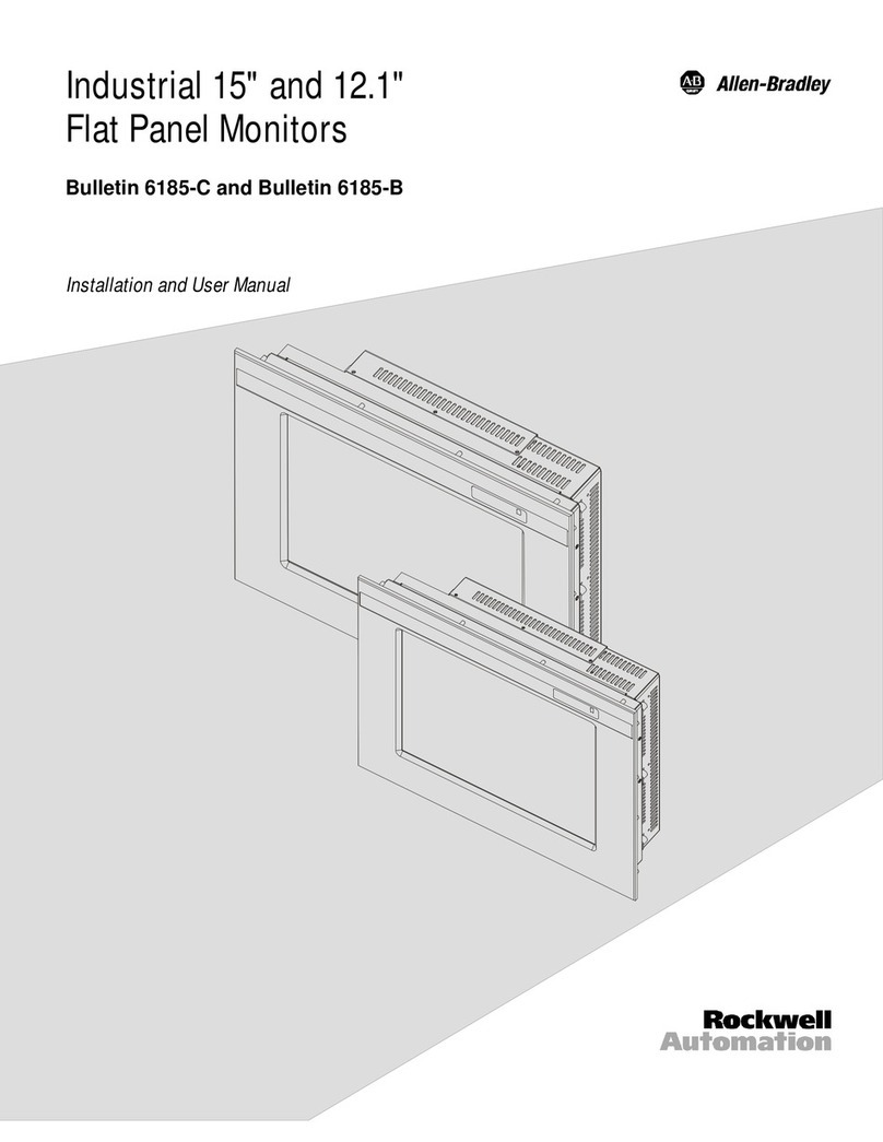
Allen-Bradley 6185-C User manual

Allen-Bradley

Allen-Bradley 6185-C User manual

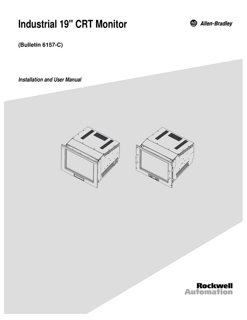
Allen-Bradley 6157-C User manual

Allen-Bradley

Allen-Bradley 6157-C User manual

Allen-Bradley VersaView 1200M User manual

Allen-Bradley

Allen-Bradley VersaView 1200M User manual

Allen-Bradley 1408 User guide

Allen-Bradley

Allen-Bradley 1408 User guide

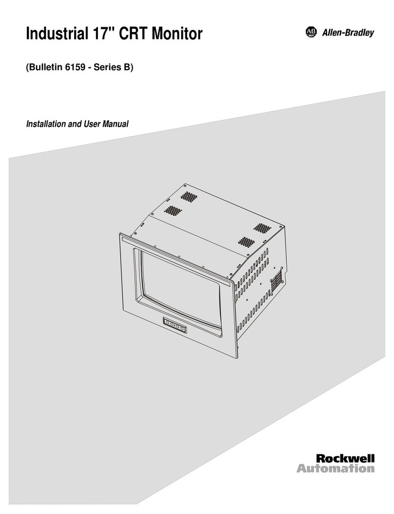
Allen-Bradley Bulletin 6159 User manual

Allen-Bradley

Allen-Bradley Bulletin 6159 User manual

Allen-Bradley InView Marquee Message Display User manual

Allen-Bradley

Allen-Bradley InView Marquee Message Display User manual

Allen-Bradley InView Marquee 2706-P42 User manual

Allen-Bradley

Allen-Bradley InView Marquee 2706-P42 User manual

Allen-Bradley A-B QUALITY DL20 Series User manual

Allen-Bradley

Allen-Bradley A-B QUALITY DL20 Series User manual

Allen-Bradley 1608S-3V480E User manual

Allen-Bradley

Allen-Bradley 1608S-3V480E User manual

Popular Monitor manuals by other brands

Samsung ME32C user manual

Samsung

Samsung ME32C user manual

ViewSonic VA926-LED user guide

ViewSonic

ViewSonic VA926-LED user guide

Furuno Mu 120c Operator's manual

Furuno

Furuno Mu 120c Operator's manual

Asus VB171D - 17" LCD Monitor Service manual

Asus

Asus VB171D - 17" LCD Monitor Service manual

AOC 9GLR Technical specifications

AOC

AOC 9GLR Technical specifications

DMG RAFFAELLO manual

DMG

DMG RAFFAELLO manual

AOC LM720 - 17" Technical specifications

AOC

AOC LM720 - 17" Technical specifications

Sony Trinitron GDM-F500 Service manual

Sony

Sony Trinitron GDM-F500 Service manual

Memorex MT1701 user guide

Memorex

Memorex MT1701 user guide

ViewSonic VE510s-4 Service manual

ViewSonic

ViewSonic VE510s-4 Service manual

Farenheit T-1503CM instruction manual

Farenheit

Farenheit T-1503CM instruction manual

Ditel DINOS DN129/AT Quick installation guide

Ditel

Ditel DINOS DN129/AT Quick installation guide

Sony SDM-S51 Specifications

Sony

Sony SDM-S51 Specifications

Kenwood DMX1025BT quick start guide

Kenwood

Kenwood DMX1025BT quick start guide

Dell S2409WFP user guide

Dell

Dell S2409WFP user guide

EverFocus EN-7517E instruction manual

EverFocus

EverFocus EN-7517E instruction manual

Dell P3222QE user guide

Dell

Dell P3222QE user guide

Panasonic TH152UX1 - 152" PLASMA TV Service manual

Panasonic

Panasonic TH152UX1 - 152" PLASMA TV Service manual

manuals.online logo
manuals.online logoBrands
  • About & Mission
  • Contact us
  • Privacy Policy
  • Terms and Conditions

Copyright 2025 Manuals.Online. All Rights Reserved.

User
Manual
Dataliner DL40 Plus
Slave Displays
Allen-Bradley
Cat. No. 2706-LV2S, -LV4S
Important User Information Because of the variety of uses for the products described in this
publication, those responsible for the application and use of this
control equipment must satisfy themselves that all necessary steps
have been taken to assure that each application and use meets all
performance and safety requirements, including any applicable laws,
regulations, codes and standards.
The illustrations, charts, sample programs and layout examples
shown in this guide are intended solely for purposes of example.
Since there are many variables and requirements associated with any
particular installation, Allen-Bradley does not assume responsibility
or liability (to include intellectual property liability) for actual use
based upon the examples shown in this publication.
Allen-Bradley publication SGI-1.1, Safety Guidelines for the
Application, Installation and Maintenance of Solid-State Control
(available from your local Allen-Bradley office), describes some
important differences between solid-state equipment and
electromechanical devices that should be taken into consideration
when applying products such as those described in this publication.
Reproduction of the contents of this copyrighted publication, in
whole or part, without written permission of Allen-Bradley
Company, Inc., is prohibited.
Throughout this manual we use notes to make you aware of safety
considerations:
Attention statements help you to:
• identify a hazard
• avoid a hazard
• recognize the consequences
Important: Identifies information that is critical for successful
application and understanding of the product.
SLC, SLC 500, SLC 5/01, SLC 5/02, SLC 5/03, SLC 5/04, PLC and PLC-5 are registered trademarks of
Allen-Bradley, Inc.
!ATTENTION: Identifies information about practices
or circumstances that can lead to personal injury or
death, property damage or economic loss.
x-2
Table of Contents
Publication 2706-6.3
Preface
Overview of this Manual . . . . . . . . . . . . . . . . . . . . . . . . . . .P-1
Chapter Objectives . . . . . . . . . . . . . . . . . . . . . . . . . . . . . . .P-1
Intended Audience . . . . . . . . . . . . . . . . . . . . . . . . . . . . . . .P-2
Conventions Used . . . . . . . . . . . . . . . . . . . . . . . . . . . . . . . .P-2
Related Publications . . . . . . . . . . . . . . . . . . . . . . . . . . . . . .P-2
Introduction to the DL40 Plus
Slave
Chapter 1
Chapter Objectives . . . . . . . . . . . . . . . . . . . . . . . . . . . . . . .1-1
Description . . . . . . . . . . . . . . . . . . . . . . . . . . . . . . . . . . . .1-1
Operating Modes . . . . . . . . . . . . . . . . . . . . . . . . . . . . . . . .1-2
DL (Dataliner) Slave Mode . . . . . . . . . . . . . . . . . . . . . . .1-2
PV (PanelView) Slave. . . . . . . . . . . . . . . . . . . . . . . . . . . .1-2
Terminal Mode . . . . . . . . . . . . . . . . . . . . . . . . . . . . . . . .1-2
Diagnostic Mode . . . . . . . . . . . . . . . . . . . . . . . . . . . . . .1-2
Features . . . . . . . . . . . . . . . . . . . . . . . . . . . . . . . . . . . . . .1-3
Typical Configurations . . . . . . . . . . . . . . . . . . . . . . . . . . . .1-4
DL40 Plus to DL40 Plus Slave . . . . . . . . . . . . . . . . . . . .1-4
PanelView to DL40 Plus Slave . . . . . . . . . . . . . . . . . . . .1-4
PLC, PC, or Other Device to DL40 Plus Slave . . . . . . . . . .1-4
Setting the DIP Switches Chapter 2
Chapter Objectives . . . . . . . . . . . . . . . . . . . . . . . . . . . . . . .2-1
DIP Switch Location . . . . . . . . . . . . . . . . . . . . . . . . . . . . . .2-1
Selecting the Operating Mode . . . . . . . . . . . . . . . . . . . . . .2-2
Display Language . . . . . . . . . . . . . . . . . . . . . . . . . . . . . . .2-2
Baud Rate . . . . . . . . . . . . . . . . . . . . . . . . . . . . . . . . . . . . .2-2
Options . . . . . . . . . . . . . . . . . . . . . . . . . . . . . . . . . . . . . . .2-3
Serial Address . . . . . . . . . . . . . . . . . . . . . . . . . . . . . . . . . .2-3
tocii
Table of Contents
Publication 2706-6.3
Installation and Startup Chapter 3
Chapter Objectives . . . . . . . . . . . . . . . . . . . . . . . . . . . . . . . . . .3-1
Mounting the DL40 Slave . . . . . . . . . . . . . . . . . . . . . . . . . . . . .3-1
Panel Cutout Dimensions . . . . . . . . . . . . . . . . . . . . . . . . . . . . .3-2
Dimensions, 2-Line Display. . . . . . . . . . . . . . . . . . . . . . . . . . . .3-3
Dimensions, 4-Line Display . . . . . . . . . . . . . . . . . . . . . . . . . . .3-3
Electrical Precautions . . . . . . . . . . . . . . . . . . . . . . . . . . . . . . . .3-4
Input Voltage Requirements . . . . . . . . . . . . . . . . . . . . . . . . . . .3-4
Hazardous Location Installations . . . . . . . . . . . . . . . . . . . . . . .3-4
RS-232 Connections . . . . . . . . . . . . . . . . . . . . . . . . . . . . . . . .3-5
DL40 Slave to DL40 Plus Master RS-232 Port . . . . . . . . . . . .3-5
DL40 Slave to PanelView RS-232 Printer Port . . . . . . . . . . . .3-6
DL40 Slave to 1771-DB BASIC Module . . . . . . . . . . . . . . . . .3-6
DL40 Slave to PLC-5 Channel 0. . . . . . . . . . . . . . . . . . . . . . .3-7
DL40 Slave to SLC Channel 0 . . . . . . . . . . . . . . . . . . . . . . . .3-7
RS-485 Connections . . . . . . . . . . . . . . . . . . . . . . . . . . . . . . . .3-8
Connecting to a DL40 Master . . . . . . . . . . . . . . . . . . . . . . . .3-9
DL40 Slave to a Computer using an RS-485 Converter Box .3-10
Relay Connections . . . . . . . . . . . . . . . . . . . . . . . . . . . . . . . . .3-11
Power Connections . . . . . . . . . . . . . . . . . . . . . . . . . . . . . . . .3-12
Startup Sequence . . . . . . . . . . . . . . . . . . . . . . . . . . . . . . . . . .3-13
Dataliner (DL) Slave Mode Chapter 4
Chapter Objectives . . . . . . . . . . . . . . . . . . . . . . . . . . . . . . . . . .4-1
Slave Mode Operation . . . . . . . . . . . . . . . . . . . . . . . . . . . . . . .4-1
Slave Mode Protocol . . . . . . . . . . . . . . . . . . . . . . . . . . . . . . . . .4-2
20 Characters for Display . . . . . . . . . . . . . . . . . . . . . . . . . . .4-2
Slave Address . . . . . . . . . . . . . . . . . . . . . . . . . . . . . . . . . . .4-2
Line Number . . . . . . . . . . . . . . . . . . . . . . . . . . . . . . . . . . . .4-2
Carriage Return . . . . . . . . . . . . . . . . . . . . . . . . . . . . . . . . . .4-2
Example Messages . . . . . . . . . . . . . . . . . . . . . . . . . . . . . . . . .4-3
Display Options . . . . . . . . . . . . . . . . . . . . . . . . . . . . . . . . . . . .4-3
[Ctrl][F] . . . . . . . . . . . . . . . . . . . . . . . . . . . . . . . . . . . . . . . . .4-3
[Ctrl][R] . . . . . . . . . . . . . . . . . . . . . . . . . . . . . . . . . . . . . . . .4-3
Clearing One or More Lines . . . . . . . . . . . . . . . . . . . . . . . . . . .4-4
Energizing Relay . . . . . . . . . . . . . . . . . . . . . . . . . . . . . . . . . . .4-4
Table of Contents
tociii
Publication 2706-6.3
PanelView (PV) Slave Mode Chapter 5
Chapter Objectives . . . . . . . . . . . . . . . . . . . . . . . . . . . . . . . . . .5-1
PV Slave Mode . . . . . . . . . . . . . . . . . . . . . . . . . . . . . . . . . . . . .5-1
PV Mode Protocol . . . . . . . . . . . . . . . . . . . . . . . . . . . . . . . . . . .5-1
Display Options . . . . . . . . . . . . . . . . . . . . . . . . . . . . . . . . . . . .5-2
[Ctrl][F](06 hex) . . . . . . . . . . . . . . . . . . . . . . . . . . . . . . . . . .5-2
[Ctrl][G](07 hex) . . . . . . . . . . . . . . . . . . . . . . . . . . . . . . . . . .5-2
[Ctrl][L](0C hex) . . . . . . . . . . . . . . . . . . . . . . . . . . . . . . . . . .5-2
[Ctrl][M](0D hex) . . . . . . . . . . . . . . . . . . . . . . . . . . . . . . . . . .5-2
[Ctrl][R](12 hex) . . . . . . . . . . . . . . . . . . . . . . . . . . . . . . . . . .5-2
[Ctrl][J](0A hex) . . . . . . . . . . . . . . . . . . . . . . . . . . . . . . . . . .5-2
Line Display Characteristics . . . . . . . . . . . . . . . . . . . . . . . . . . .5-3
Line to line Delay. . . . . . . . . . . . . . . . . . . . . . . . . . . . . . . . . .5-3
Cursor Movement Delay . . . . . . . . . . . . . . . . . . . . . . . . . . . .5-3
Terminal Mode Chapter 6
Chapter Objectives . . . . . . . . . . . . . . . . . . . . . . . . . . . . . . . . . .6-3
Terminal Mode Operation . . . . . . . . . . . . . . . . . . . . . . . . . . . . .6-3
Terminal Mode Protocol . . . . . . . . . . . . . . . . . . . . . . . . . . . . . .6-4
Cursor Up (Ctrl-K) . . . . . . . . . . . . . . . . . . . . . . . . . . . . . . . . .6-4
Cursor Down (Ctrl-V) . . . . . . . . . . . . . . . . . . . . . . . . . . . . . . .6-4
Cursor Left (Ctrl-H) . . . . . . . . . . . . . . . . . . . . . . . . . . . . . . . .6-4
Cursor Right (Ctrl-L) . . . . . . . . . . . . . . . . . . . . . . . . . . . . . . .6-4
Cursor Return (Ctrl-M) . . . . . . . . . . . . . . . . . . . . . . . . . . . . . .6-4
Line Feed (Ctrl-J). . . . . . . . . . . . . . . . . . . . . . . . . . . . . . . . . .6-4
Clear Screen (ESC and then *) . . . . . . . . . . . . . . . . . . . . . . .6-4
New Line (Ctrl-_). . . . . . . . . . . . . . . . . . . . . . . . . . . . . . . . . .6-5
Set Cursor Position (ESC,=,<row>,<column>) . . . . . . . . . . .6-5
Set Cursor Invisible (ESC . 0) . . . . . . . . . . . . . . . . . . . . . . . . .6-5
Set Cursor Visible (ESC . 1) . . . . . . . . . . . . . . . . . . . . . . . . . .6-5
De-energize Relay (ESC . 2). . . . . . . . . . . . . . . . . . . . . . . . . .6-5
Energize Relay (ESC . 3) . . . . . . . . . . . . . . . . . . . . . . . . . . . .6-5
Set Flashing Mode (ESC G 2) . . . . . . . . . . . . . . . . . . . . . . . . .6-5
Clear Flashing Mode (ESC G 0) . . . . . . . . . . . . . . . . . . . . . . .6-5
Monitor Mode (ESC U) . . . . . . . . . . . . . . . . . . . . . . . . . . . . . .6-6
Exit Monitor Mode (ESC u) or (ESC X). . . . . . . . . . . . . . . . . . .6-6
Display Status (ESC h) . . . . . . . . . . . . . . . . . . . . . . . . . . . . . .6-6
Diagnostic Mode Chapter 7
Chapter Objectives . . . . . . . . . . . . . . . . . . . . . . . . . . . . . . . . . .7-1
Using the Diagnostic Mode . . . . . . . . . . . . . . . . . . . . . . . . . . . .7-1
Serial Port Settings . . . . . . . . . . . . . . . . . . . . . . . . . . . . . . . .7-1
Data Received Display . . . . . . . . . . . . . . . . . . . . . . . . . . . . .7-1
Data Errors . . . . . . . . . . . . . . . . . . . . . . . . . . . . . . . . . . . . . .7-2
tociv
Table of Contents
Publication 2706-6.3
Specifications Appendix A
Display Characters . . . . . . . . . . . . . . . . . . . . . . . . . . . . . . . . A-1
Electrical . . . . . . . . . . . . . . . . . . . . . . . . . . . . . . . . . . . . . . . A-1
Serial Communications . . . . . . . . . . . . . . . . . . . . . . . . . . . . A-1
Environmental . . . . . . . . . . . . . . . . . . . . . . . . . . . . . . . . . . . A-2
Mechanical . . . . . . . . . . . . . . . . . . . . . . . . . . . . . . . . . . . . . A-2
Certifications. . . . . . . . . . . . . . . . . . . . . . . . . . . . . . . . . . . . . A-2
Character Sets Appendix B
ASCII (English) Character Set . . . . . . . . . . . . . . . . . . . . . . . . B-1
Extended ASCII Character Set . . . . . . . . . . . . . . . . . . . . . . . . B-2
Cyrillic Character Set . . . . . . . . . . . . . . . . . . . . . . . . . . . . . . B-3
International Character Set . . . . . . . . . . . . . . . . . . . . . . . . . . B-4
Slave Address Settings Appendix C
SLC/PLC Program Examples Appendix D
PLC-5 Channel 0 to DL40 Plus Slave . . . . . . . . . . . . . . . . . . D-1
SLC Channel 0 to DL40 Plus Slave . . . . . . . . . . . . . . . . . . . . D-2
Publication 2706-6.3
Preface
Using this Manual
Chapter Objectives Read this chapter to familiarize yourself with the rest of the Dataliner
DL40 Plus Slave Message Display manual. You will learn about:
• contents of this manual
• intended audience
• conventions used
• related publications
Overview of this Manual This manual describes how to install and use your DL40 Plus Slave
display. This manual contains the following:
Chapter Title Purpose
1 Introduction to the DL40
Slave Display Describes basic features and operating
capabilities.
2 Setting the DIP Switches Describes configuration of the display
using the DIP switches.
3 Installation and Startup Provides installation and wiring
instructions. The status display
sequence on powerup is described.
4 Dataliner (DL) Slave Mode Describes operation of the display in the
DL Slave Mode (the display receives
message information from a DL40 Plus
master display or enhanced PanelView
terminal).
5 PanelView (PV) Slave Mode Describes operation of the display in the
PV Slave Mode (displays data that would
normally be printed on the PanelView
printer port).
6 Terminal Mode Describes operation of the display in the
Terminal Mode. In this mode, the slave
display receives ASCII message and
formatting data from a host device.
7 Diagnostic Mode Describes how to use the diagnostic
mode to correct communication
problems or data formatting errors.
Appendix A Specifications Mechanical and electrical specifications.
Appendix B Character Sets Standard / Extended ASCII, Cyrillic, and
International Character sets.
Appendix C Slave Address Settings Table listing DIP switch settings for each
address (1 to 255).
Appendix D PLC / SLC Examples SLC / PLC programming examples.
Publication 2706-6.3
P-2
Preface
Intended Audience No specialized knowledge is required to configure and install the
DL40 slave display. However, we assume the following:
• The person responsible for equipment connections is familiar
with standard wiring practices and electrical codes in your area.
• Communication cabling is done by a person having an
understanding of basic communications terminology and cabling.
• Panel cutouts are made using the same methods and safety
practices followed for other panel mounted equipment.
Conventions Used The following conventions are used in this manual.
• The up caret, ^, may be used in place of [Ctrl] (Control key)
where space is limited.
• Values in a hexadecimal format have the suffix “hex”. For
example “B7 hex”.
Related Publications You may need to refer to the following related publications:
Publication Title Description Publication
Number
Dataliner DL40 Plus Message
Display User Manual Provides installation, wiring and
operating instructions for the DL40
Plus display (not slave display). Also
describes use of the onboard
message editor.
2706-6.1
DL40 Plus Offline Programming
Software User Manual Describes installation and use of the
DOS based message development
software for the DL40 Plus.
2706-6.2
PanelBuilder Software
User Manual Describes how to output messages
to the PanelView printer port for
display on the DL40 slave.
2711-6.0
PanelBuilder 1400e
Configuration Software for
Windows User Manual
Provides useful information when
using a PanelView enhanced
terminal as a master for a DL40 Plus
slave.
2711e-819
Publication 2706.6.3
Chapter 1
Introduction to the DL40 Plus Slave
Chapter Objectives This chapter describes the DL40 Plus Slave display and summarizes
its capabilities. The following topics are included in this chapter:
• DL40 Plus Slave description
• Operating modes
• Features
• Typical configurations
Description The DL40 Plus Slave displays are available in two-line and four-line
versions. These displays are designed for panel mounting in industrial
environments and require a 110-240V AC power source.
DL40 Plus Slave displays receive message text from a host device.
The host device may be a DL40 Plus master display, PanelView
terminal, programmable controller, or a personal computer. All
messages are created and stored in the host device.
The DL40 Plus Slave displays appear similar to the standard DL40
Plus two and four-line displays except they do not have front panel
buttons, indicator LEDs, keyboard port, or an RIO / parallel port.
2706-LV4S
2706-LV2S