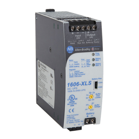
Allen-Bradley 1606-XLS240-UPSC User manual

DC-UPS with Integrated Battery - 24V, 10 A
Catalog Number 1606-XLS240-UPSC
Reference Manual
Original Instructions

Important User Information
Read this document and the documents listed in the additional resources section about installation, configuration, and
operation of this equipment before you install, configure, operate, or maintain this product. Users are required to
familiarize themselves with installation and wiring instructions in addition to requirements of all applicable codes, laws,
and standards.
Activities including installation, adjustments, putting into service, use, assembly, disassembly, and maintenance are
required to be carried out by suitably trained personnel in accordance with applicable code of practice.
If this equipment is used in a manner not specified by the manufacturer, the protection provided by the equipment may
be impaired.
In no event will Rockwell Automation, Inc. be responsible or liable for indirect or consequential damages resulting from
the use or application of this equipment.
The examples and diagrams in this manual are included solely for illustrative purposes. Because of the many variables and
requirements associated with any particular installation, Rockwell Automation, Inc. cannot assume responsibility or
liability for actual use based on the examples and diagrams.
No patent liability is assumed by Rockwell Automation, Inc. with respect to use of information, circuits, equipment, or
software described in this manual.
Reproduction of the contents of this manual, in whole or in part, without written permission of Rockwell Automation,
Inc., is prohibited.
Throughout this manual, when necessary, we use notes to make you aware of safety considerations.
Labels may also be on or inside the equipment to provide specific precautions.
WARNING: Identifies information aboutpractices or circumstances that can cause an explosion in a hazardous
environment, which may lead to personal injury or death, property damage, or economic loss.
ATTENTION: Identifies information about practices or circumstances that can lead to personal injury or death, property
damage, or economic loss. Attentions help you identify a hazard, avoid a hazard, and recognize the consequence.
IMPORTANT Identifies information that is critical for successfulapplication and understanding of the product.
SHOCK HAZARD: Labels may be on or inside the equipment, for example, a drive or motor, to alert people that dangerous
voltage may be present.
BURNHAZARD:Labels may be onor inside theequipment, for example, adriveormotor,toalert peoplethatsurfacesmay
reach dangerous temperatures.
ARC FLASH HAZARD: Labels may be on or inside the equipment, for example, a motor control center, to alert people to
potentialArcFlash.ArcFlashwillcausesevereinjuryor death.WearproperPersonalProtectiveEquipment(PPE).FollowALL
Regulatory requirements for safe work practices and for Personal Protective Equipment (PPE).
Rockwell Automation Publication 1606-RM003A-EN-P - March 2019 3
DC-UPS with Integrated battery - 24V, 10 A
Table of Contents
Additional Resources These documents contain additional information concerning related products
from Rockwell Automation.
You can view or download publications at
http://www.rockwellautomation.com/global/literature-library/overview.page.
To order paper copies of technical documentation, contact your local
Allen-Bradley distributor or Rockwell Automation sales representative.
Topic Page Topic Page
Additional Resources 3 Terminals andWiring 17
Terminology and Abbreviations 4 Lifetime Expectancy and Mean Time between
Failure 18
Product Overview 4 EMC 19
Input 6 Environment 20
Output in Normal Mode 7 Protection Features 21
Output in Buffer Mode 8 Safety Features 21
Battery 10 Standards Compliance and Approvals 22
Buffer Time 11 Approximate Dimensions and Weight 23
Efficiency and Power Loss 11 Installation Notes 23
Functional Diagram 12 Battery Replacement 25
CheckWiring and Battery Quality Tests 12 Accessories 29
Relay Contacts and Inhibit Input 14 Application Notes 30
Front Side and User Elements 16 Troubleshooting 31
Resource Description
Industrial AutomationWiring and Grounding Guidelines,
publication 1770-4.1 Provides general guidelines for installing a Rockwell
Automation® industrial system.
Product Certifications website, http://
www.rockwellautomation.com/global/certification/
overview.page
Provides declarations of conformity, certificates, and
other certification details.

4Rockwell Automation Publication 1606-RM003A-EN-P - March 2019
DC-UPS with Integrated Battery - 24V, 10 A
Terminology and
Abbreviations
Product Overview This uninterrupted power
supply (UPS) controller with
integrated battery is a compact
additiontostandard24Vpower
supplies to bridge power
failures or voltage fluctuations.
Expensive downturns, long
restart cycles, and loss of data
can be avoided.
The DC-UPS includes a
professional battery
management system, which
charges and, monitors the
battery to achieve the longest
battery service life and many
diagnostic functions that ensure
a reliable operation of the entire
system.
A unique feature of the 1606-XLS240-UPSC is that only one 12V battery is
required to buffer the 24V output. This makes matching batteries unnecessary
and allows a precise battery charging and testing.
The power supply has one easy-to-change integrated 12V, 5 A high-current
VRLA battery.
In addition to the power supply, a separate UPS controller which requires an
external 12V battery is available when a longer buffer time is required.
The power supply includes these features:
• Compact size and easy installation
• Longest buffer time in class
• Easy battery access
• Stable output voltage in buffer mode
Term Definition
DC-UPS Uninterpretable power supply with DC input.
Normal mode Describes a condition where the battery is charged, the input voltage is in range, and the
output is loaded within the allowed limits.
Buffer mode Describes a condition where the input voltage is below the transfer threshold level, the unit is
running on battery (buffering) and the output is loaded within the allowed limits.
Charging mode Describesa conditionwherethebatteryisbeingcharged,theinputvoltageis inrangeandthe
output is loaded within the allowed limits.
Inhibit mode Describes a condition where buffering is disabled on purpose by using the inhibit input of the
DC-UPS. (For example, for service actions, or to save battery capacity)
Buffer time Same as the term hold-up time.

Rockwell Automation Publication 1606-RM003A-EN-P - March 2019 5
DC-UPS with Integrated battery - 24V, 10 A
• Superior battery management for long battery life
• Temperature compensated battery charging
• Comprehensive diagnostics and monitoring functions
• Replace battery signal included
• Electronically overload and short circuit protection
• 50% power reserves
• Selectable buffer time limiter
The power supply is also environmentally friendly:
• The unit does not release any silicone and is suitable for the use in paint
shops.
• The unit conforms to the RoHS directive 2002/96/EC.
• Electrolytic capacitors included in this unit do not use electrolytes such as
Quaternary Ammonium Salt Systems.
• Plastic housings and other molded plastic materials are free of halogens.
• The materials that are used in our production process do not include
Polychlorinated Biphenyl (PCB), Pentachlorophenol (PCP),
Polychlorinated naphthalene (PCN), Polybrominated Biphenyl (PBB),
Polybrominated Biphenyl Oxide (PBO), Polybrominated Diphenyl Ether
(PBDE), Polychlorinated Diphenyl Ether (PCDE), Polybrominated
Diphenyl Oxide (PBDO), Cadmium, Asbestos, Mercury, or Silica.
Figure 1 - Typical Setup of a DC-UPS System withthe 1606-XLS240-UPSC
Attribute Description
Input voltage
Range
24V DC, nom
22.5…30V DC
–
Output current 15 A, min
10 A, min
Normal mode
Buffer mode
Output voltage Typ 0.23V lower as input voltage
22.25V
Normal mode
Buffer mode, 10 A
Integrated battery 12V, 5 Ah VRLA lead acid
Temperature range 0…40 °C(32…104 °F) Operational
Size (W x H x D) 123 x 124 x 11 mm
(4.84 x 4.88 x 0.43 in.)
–
Buffer time 16 minutes, 15 s, typ
16 minutes, 15 s, typ
5 A load
10 A load
(For example, PLC)

6Rockwell Automation Publication 1606-RM003A-EN-P - March 2019
DC-UPS with Integrated Battery - 24V, 10 A
Figure 2 - Markings
Input
UL 60950-1 Class 1 Div 2
Marine
IND. CONT. EQ.
UL 508
Attribute Description
Input voltage Nom 24V DC
Input voltage ranges Nom 22.5…30V DC Continuous operation, see Figure 3.
30…35V DC Temporarily allowed, no damage to the DC-UPS.(2)
35V DC Absolute maximum input voltage with no damage to the DC-UPS.
0…22.5V DC The DC-UPS changes to Buffer modeand delivers output voltage
from the battery if the input is above the turn-on level before and
all other buffer conditions are fulfilled.
Allowedinput voltage ripple Max 1.5V pp
1V pp
Bandwidth < 400 Hz
Bandwidth 400 Hz to 1 kHz
Allowed voltage between input and
earth (ground) Max 60V DC or 42.4V AC
Turn-on voltage Typ 22.8V DC The output does not switch On if the input voltage does not
exceed this level.
Max 23V DC
Input current(1) Typ
Typ
120 mA
1.1 A
Internal current consumption
Current consumption for battery charging in constant current
mode at 24V input. See Figure 13.(3)
External capacitors on the input No limitation
(1) The unit shows‘CheckWiring’with the red LED and buffering is not possible.
(2) The total input current is the sum of the output current, the current that is required to charge the battery during the charging process and the current that is needed to supply the
DC-UPS itself. See Figure 4. This calculation does not apply in overload situations where the DC-UPS limits the output current. See Figure 5.
(3) This is the input currentand not the current that flows into the battery during charging. See for the battery current.
Figure 3 - Input Voltage Range Figure 4 - Input Current, Definitions

Rockwell Automation Publication 1606-RM003A-EN-P - March 2019 7
DC-UPS with Integrated battery - 24V, 10 A
Electronic Output Current Limitation
The unit is equipped with an electronic output current limitation. This current
limitation works in a switching mode that reduces the power losses and heat
generation to a minimum. As a result, the output voltage drops since there is not
enough current to support the load. A positive effect of the current limitation in
switching mode is that the input current goes down despite an increase in the
output current resulting in less stress for the supplying source.
Figure 5 - Input Currentand Output Voltage versus Output Current, Typ.(battery fully charged)
OutputinNormalMode
Attribute Description
Output voltage Nom DC 24V The output voltage follows the input voltage that is
reduced by the input to the output voltage drop.
Voltage drop between
input and output Max
Max
0…3V
0.45V
At 10 A output current, see Figure 6 for typical
values.
At 15 A output current, see Figure 6 for typical
values.
Ripple and noise
voltage Max 20 mVpp 20 Hz to 20 MHz, 50 Ohms(1)
(1) Shows the ripple and noise voltage that is generated by the DC-UPS.The ripple and noise voltage might be higher if the supplying
source has a higher ripple and noise voltage.
Output current Nom 15 A Continuously allowed
Output power Nom 360W Continuously allowed
Short circuit current Min
Max
17.9 A
21 A
Load impedance 100 mOhm, see Figure 7 for typical
values.
Load impedance 100 mOhm, see Figure 7 for typical
values.
Capacitive and
inductive loads No limitation

8Rockwell Automation Publication 1606-RM003A-EN-P - March 2019
DC-UPS with Integrated Battery - 24V, 10 A
Output in Buffer Mode If the input voltage falls below a certain value (transfer threshold level), the
DC-UPS starts buffering without any interruption or voltage dips. Buffering is
possible even if the battery is not fully charged.
Figure 6 - Input to Output Voltage Drop,Typ. Figure 7 - Output Voltage versus Output Current in Normal
Mode at 24V Input, Typ.
Attribute Description
Output voltage Nom 24V DC
22.45V
22.25V
The outputvoltage is stabilizedand independent from the
battery voltage.
at no load
at 10 A output current
Transfer threshold for
buffering Typ 80 mV greater than the output voltage in buffer mode.
Ripple and noise
voltage Max 20 mVpp 20 Hz to 20 MHz, 50 Ohms
Output current Nom 10 A
15 A
Continuously allowed
<5 s with full output voltage(1)
(1) If the output current is in the range 10 A…15 A for longer than5 s, a hardware-controlled reduction of the maximal output current
to 10 A occurs. If the 10 A are not sufficient to maintain the 24V, buffering stops after another 5 s. The buffering is possible again as
soon as the input voltage recovers.
Short Circuit current Min
Max
17.9 A
21 A
Load impedance 100 mOhm(2)
(2) If the nominal output voltage cannot be maintained in buffer mode, the DC-UPS switches off after 5 s to save battery capacity.

Rockwell Automation Publication 1606-RM003A-EN-P - March 2019 9
DC-UPS with Integrated battery - 24V, 10 A
Figure 8 - Buffering Transition, Definitions Figure 9 - Transfer Behavior, Typ.
Figure 10 - Available Output Current in Buffer Mode Figure 11 - Output Voltage versus Output Current in Buffer
Mode,Typ.
5 Seconds

10 Rockwell Automation Publication 1606-RM003A-EN-P - March 2019
DC-UPS with Integrated Battery - 24V, 10 A
Battery The required 12V VRLA battery is included with this unit.
Attribute Description
Battery voltage Nom 12V DC Maintenance-free 12VVRLA lead acid battery
Battery voltage range
Max
Typ
9.0…15V
35V DC
7.4V
Continuously allowed, except deep discharge protection.
Absolute maximum voltage with no damage to the unit.
Battery charging is possible above this level.
Allowed battery capacity Nom 5 Ah High-current version
Battery charging method CC-CV Constant current, constantvoltage mode
Battery charging current Nom
Max
1.5 A
1.7 A
CC-mode, independent from battery size
Corresponding 24V input current. See Figure 13.
End-of-charge voltage (CV-mode) Typ 13.1…14V Automatic setting according to ambient temperature
Battery charging time Typ 3 h(3) –
Battery discharging current(1) Typ
Typ
Max
Typ
21 A
0.3 A
50
270 mA
Buffer mode, 10 A output current, 11.5V on the battery
terminal of the unit.
Buffer mode, 0 A output current
At no input, buffering had turned off, all LEDs are off.
At no input, buffering had turned off, yellow LED shows
that buffer time has expired, (max. 15 minutes).
Deep discharge protection(2) Typ
Typ
10.5V
9V
At 0 A output current
At 10 A output current
(1) The current between the battery and the DC-UPS is more than twice the output current.This is caused by boosting the 12V battery voltage to a
24V level.
(2) To ensure longest battery lifetime, the DC-UPS has a battery deep discharge protection feature included.The DC-UPS stops buffering when the
voltage on the battery terminals of the DC-UPS falls below a certain value.
(3) The charging time depends on the duration and load current of the last buffer event. The numbers in the table represent a fully discharged
battery. A typical figure for a buffer current of 10 A is 2 hours, 20 minutes for a 5 Ah high-current battery.Above 40 °C(104 °F) charging time can
be longer.
Figure 12 - Battery Discharging Current versus Output Current, Typ. Figure 13 - Required InputCurrent versus InputVoltage for
Battery Charging

Rockwell Automation Publication 1606-RM003A-EN-P - March 2019 11
DC-UPS with Integrated battery - 24V, 10 A
BufferTime The buffer time depends on the capacity and performance of the battery and the
load current. See Figure 14 for the typical buffer times of the standard battery.
Figure 14 - Buffer Time versus Output Current with a 5 Ah High-current Battery
Efficiency and Power Loss
Attribute 1606-XLS240-UPSC Notes
Buffer time with 5 A
high-current battery Min
Min
Typ
Typ
13’24”
4’54”
16’15”
6’15”
At 5 A output current(1)
At 10 Aoutput current(1)
At 5 A output current, see Figure 14.(2)
At 10 Aoutput current, see Figure 14.(2)
(1) Minimum value includes 20% aging and requires a fully charged (min. 24 h) battery.
(2) Typical value includes 10% aging and requires a fully charged (min. 24 h) battery.
1606-XLSBAT5
Attribute Description
Efficiency Typ 97.8% Normal mode, 10 A output
current, battery fully charged
Power losses Typ 2.9 W Normal mode, 0 A output
current, battery fully charged
Typ 5.5W Normal mode, 10 A output
current, battery fully charged
Typ 5.0W 0 A output current during
battery charging
Figure 15 - Efficiency at 24V, typ. Figure 16 - Losses at 24V, typ.

12 Rockwell Automation Publication 1606-RM003A-EN-P - March 2019
DC-UPS with Integrated Battery - 24V, 10 A
Functional Diagram Figure 17 - Functional Diagram
CheckWiring and Battery
QualityTests
The DC-UPS is equipped with an automatic Check Wiring and Battery Quality
test.
CheckWiringTest
Under normal circumstances, an incorrect or bad connection from the battery to
the DC-UPS or a missing (or blown) battery fuse is not recognized by the UPS
when operating in normal mode. Only when backup is required would the unit
not be able to buffer. Therefore, a Check Wiring test is included in the
DC-UPS. This connection is tested every 10 seconds by loading the battery and
analyzing the response from the battery. If the resistance is too high, or the
battery voltage is not in range, the unit displays Check Wiring with the red LED.
At the same time, the green Ready LED turns off.

Rockwell Automation Publication 1606-RM003A-EN-P - March 2019 13
DC-UPS with Integrated battery - 24V, 10 A
State of Health (SOH) Test
The battery has a limited service life and needs to be replaced in a fixed interval
that is defined by the specified service life (according to the Eurobat guideline),
based on the surrounding temperature and the number of charging and
discharging cycles. If the battery is used longer than the specified service life, the
battery capacity degrades. The SOH test cannot determine a gradual loss in
capacity. However, it can detect a battery failure within the specified service life
of the battery. Therefore an SOH test is included in the DC-UPS.
The SOH test consists of different types of tests.
During Charging
If the battery does not reach the ready status within 30 hours, it is considered to
be defective. The reason could be a broken cell inside the battery.
During Operation
Once the battery is fully charged, a voltage drop test and a load test are performed
alternately every 8 hours. Three of the tests must consecutively produce negative
results to indicate a battery problem.
A battery problem is indicated with the yellow LED (replace battery pattern) and
the relay contact Replace Battery. It can take up to 50 hours until a battery
problem is reported. This should avoid nuisance error messages as any urgent
battery problems are reported by the Check Wiring test and create a warning
signal.
The battery tests require up to 50 hours uninterrupted operation. Any
interruptions in the normal operation of the DC- UPS may result in the Replace
Battery test cycle to start over.
When replace battery is indicated, replace the battery as soon as possible.

14 Rockwell Automation Publication 1606-RM003A-EN-P - March 2019
DC-UPS with Integrated Battery - 24V, 10 A
Relay Contacts and Inhibit
Input
The DC-UPS is equipped with relay contacts and signal inputs for remote
monitoring and controlling of the unit.
Relay Contacts
Signal Input
Contact State
Ready Contact is closed when battery is charged more than 85%, no wiring failure are recognized, input
voltage is sufficient, and inhibit signal is not active.
Buffering Contact is closed when unit is buffering.
Replace battery Contact is closed when the unit is powered from the input and the battery quality test (SOH test)
reports a negative result.
Attribute Description
Relay Contact ratings Max
Min
60V DC, 0.3 A, 30V DC, 1 A, 30V AC, 0.5 A resistive load
1 mA at 5V DC min.
Isolation voltage Max 500V AC, signal port to power port
Contact State
Ready The inhibit input disables buffering. In normal mode, a static signal is required. In buffer mode, a pulse
with a minimum length of 250 ms isrequired to stop buffering.The inhibit is stored and is reset by
cycling the input voltage.
Attribute Description
Signal voltage Max 35V DC
Signal current Max 6 mA, current limited
Inhibit threshold Min
Max
6V DC, buffering is disabled above this threshold level
10V DC
Isolation Nom 500V AC, signal port to power port

Rockwell Automation Publication 1606-RM003A-EN-P - March 2019 15
DC-UPS with Integrated battery - 24V, 10 A
Figure 18 - Contact Control of Drawing for Use in Hazardous Location Environments
IMPORTANT The Buffering, Ready, and Replace Battery contact is intended to be used for a
separately investigated nonincendive field wiring and/or field wiring
apparatus. The DC-UPS may be located in a Class I, Division 2 (GroupA, B, C,or
D) hazardous (classified) location. Associated apparatus must be installed in
accordance with its manufacturer's control drawing and Article 504 of the
National Electrical Code (ANSI/NFPA 70) for installation in the UnitedStates, or
Section 18 of the Canadian Electrical Code for Installations in Canada.
Selected associated apparatus must be third part that is listed as providing
nonincendivefield circuits for the application, and haveVoc not exceeding
Vmax, Isc not exceeding Imax.
Non-Associated nonincendive field wiring apparatuses shall not be connected
in parallel unless this is permitted by the associated nonincendive field wiring
apparatuses approval.

16 Rockwell Automation Publication 1606-RM003A-EN-P - March 2019
DC-UPS with Integrated Battery - 24V, 10 A
Front Side and User
Elements
C
D
F
E
A
Letter Definition
A Power port - Quick-connect spring-clamp terminals, connection for input voltage and output voltage.
BSignalport- Plug connector with screw terminals, which are inserted from the bottom. Connections for
the Ready, Buffering, Replace Battery relay contacts and for the Inhibit input.
C Green Status LED -
Ready: Battery is charged > 85%, no wiring failures are recognized, input voltage is sufficient and inhibit
signal is not active.
Charging: Battery is charging and the battery capacity is below 85%.
Buffering: Unit is in buffer mode.
Figure 19 -Green LED Flashing Pattern
D Yellow Diagnosis LED -
Overload: Output has switched off due to long overload in buffer mode or due tohigh temperatures.
Replace battery: Indicates a battery that failed the battery quality test (SoH test).The battery should be
replaced as soon as possible.
Buffer-time expired: Output has switched off due to settings of Buffer- timer Limiter. This signal is
displayed for 15 minutes.
Inhibit active: Indicates that buffering is disabled due to an active inhibit signal.
Figure 20 - Yellow Diagnostic LED
E RedCheck WiringLED -ThisLEDindicatesafailure intheinstallation (forexample toolow input voltage),
wiring,battery, or battery fuse.
F Buffer-time Limiter -The dial limits the maximum buffer time in a buffer event to save battery energy.
When the battery begins to recharge after a discharging event, the process is completed much faster since
only the energy, which was taken out of the battery, needs to be replenished. Buffering durations include
10 s, 30 s, 1 minute, 3 minutes, 10 minutes, and infinity (until the battery is discharged) which allows
buffering until the deep discharge helps protect stops buffering.

Rockwell Automation Publication 1606-RM003A-EN-P - March 2019 17
DC-UPS with Integrated battery - 24V, 10 A
Terminals and Wiring
Figure 21 - Connecting a Wire with Spring-clamp Terminals
• Use appropriate copper cables that are designed for an operating
temperature of 60 °C (140 °F)
• Follow national installation codes and regulations.
• Ensure that all strands of a stranded wire enter the terminal connection.
• You can use up to two stranded wires with the same cross section in one
connection point.
Attribute PowerTerminals SignalTerminals
Type Bi-stable, quick-connect
spring- clamp terminals. IP20
Finger-touch-proof. Suitable for
field and factory installation.
Shipped in open position.
Plugconnectorwith screwterminal.
Finger-touch-proof construction
with captive screws for 3.5 mm
slottedscrewdriver.Suitableforfield
and factory installation. Shipped in
open position. To meet GL
requirements, unused terminal
compartments should be closed.
Solid wire 0.5…6 mm20.2…1.5 mm2
Stranded wire 0.5…4 mm20.2…1.5 mm2
AmericanWire Gauge AWG 20…10 AWG 22…14
Ferrules Allowed but not required Allowed but not required
Pull-out force 10 AWG:80 N, 12 AWG:60 N
14 AWG:50 N, 16 AWG:40 N
according to UL486E
Not applicable
Tightening torque Not applicable 1 Nm, 9 lb-in
Wiring stripping length 10 mm (0.4 in.) 6 mm (0.24 in.)

18 Rockwell Automation Publication 1606-RM003A-EN-P - March 2019
DC-UPS with Integrated Battery - 24V, 10 A
Lifetime Expectancy and
Mean Time between
Failure
Attribute Description
Lifetime
expectancy(1) – min. 137,400 h at 10 A output current and 40 °C (104 °F)
min. > 15 years at 5 A output current and 40 °C (104 °F)
min. > 15 years at 10 A output current and 25 °C (77 °F)
MTBF(2) SN 29500, IEC 61709 886,000 h at 10 A output current and 40 °C (104 °F)
1,482,000 h at 10 A output current and 25 °C (77 °F)
MIL HDBK 217 F 397,900 h at 10 A output current and 40 °C (104 °F), Ground Benign GB40
545,000 h at 10 A output currentand 25 °C (77 °F), Ground Benign GB25
(1) The Lifetime expectancy that is shown in the table indicates the minimum operating hours (service life) and is determined by the lifetime expectancy of the
built-in electrolytic capacitors. Lifetime expectancy is specified in operational hours and is calculated according to the capacitors manufacturer specification. The
prediction model allows a calculation of up to 15 years (131,400 h) from date of shipment.
(2) MTBF represents Mean Time Between Failure, which is calculated according to statistical device failures, and indicates reliability of a device. It is the statistical
representation of the likelihood of a unit to fail and does not necessarily represent the life of a product.
All values except a battery.

Rockwell Automation Publication 1606-RM003A-EN-P - March 2019 19
DC-UPS with Integrated battery - 24V, 10 A
EMC The unit is suitable for applications in industrial environment and in residential,
commercial, and light industry environment without any restrictions. CE mark is
in conformance with EMC guideline 89/336/EC and 93/68/EC and the low-
voltage Low Voltage Directive (LVD) 73/23/EC, 93/68/EC.
EMC Immunity Accordingto Generic Standards EN 61000-6-1 and EN 61000-6-2 Criterion
Electrostatic discharge EN 61000-4-2 Contact discharge
Air discharge
8 kV
15 kV
CriterionA(2)
Criterion A(2)
(2) DIN rail earthed.
Electromagnetic RF field EN 61000-4-3 80 MHz-1 GHz 10V/m Criterion A
Fast transients (Burst) EN 61000-4-4 Input lines
Output lines
Signal lines(1)
(1) Tested with coupling clamp.
2 kV
2 kV
2 kV
Criterion A
Criterion A
Criterion A
Surge voltage EN 61000-4-5 Output + ->-
Input + ->-
+ -> housing
500V
500V
500V
Criterion A
Criterion A
Criterion A
Conducted disturbance EN 61000-4-6 0.15…80 MHz 10V Criterion A
EMC Emission According to Generic Standards: EN 61000-6-3, EN 610000-6-4
Conducted emission EN 55022 input lines
EN 55022 output lines
Class B(1)
Class B(1)
(1) Informative measurement with voltage probe.
Radiated emission EN 55011, EN 55022 Class B
This device complies with FCC Part 15 rules. Operation is subjected to following two conditions: (1) this device cannot
cause harmful interference, and (2) this device must accept any interference received, including interference that can
cause undesired operation.
Switching Frequency(1)
(1) The unit has three converters with three different switching frequencies included.
Description
Switching frequency of boost converter
Switching frequency of electronic output current limitation
Switching frequency of battery charger
100 kHz
78 kHz
19.5 kHz
Constant frequency
Constant frequency
Constant frequency

20 Rockwell Automation Publication 1606-RM003A-EN-P - March 2019
DC-UPS with Integrated Battery - 24V, 10 A
Environment
Attribute Description
Operational temperature 0…40 °C (32…104 °F) Full output power
Storage temperature -20…+50 °C (-4…+122 °F) Storage and transportation
Relative humidity 5…95% IEC 60068-2-30
Do not energize while condensation is present.
Vibration sinusoidal(1)
(1) Use wall mounting accessory for greater values.
2…17.8 Hz: ±1.6 mm (0.62 in.);
17.8…500 Hz: 1 g (0.03 oz) IEC 60068-2-6
Shock 15 g (0.52 oz) 6 ms,
10 g (0.35 oz) 11 ms IEC 60068-2-27
Altitude 0…6000 m (0…20,000 ft.) Approvals apply up to 2000 m (6560 ft).
Overvoltage category III EN 50178
II EN 50178, altitudes above 2000 (6560 ft)
Degree of pollution 2 EN 50178, non-conductive
Figure 22 - Nominal Mode - Output Current versus Ambient
Temperature Figure 23 - Buffer Mode - Output Current versus Ambient
Temperature
Table of contents
Other Allen-Bradley UPS manuals

Allen-Bradley
Allen-Bradley 1609-P8000E User manual

Allen-Bradley
Allen-Bradley Bulletin 1609 User manual

Allen-Bradley
Allen-Bradley 1609-P3000N User manual

Allen-Bradley
Allen-Bradley 1609-P3000N User manual

Allen-Bradley
Allen-Bradley Bulletin 1609 User manual

Allen-Bradley
Allen-Bradley ControlNet PLC-5 User manual

Allen-Bradley
Allen-Bradley DC-UPS User manual