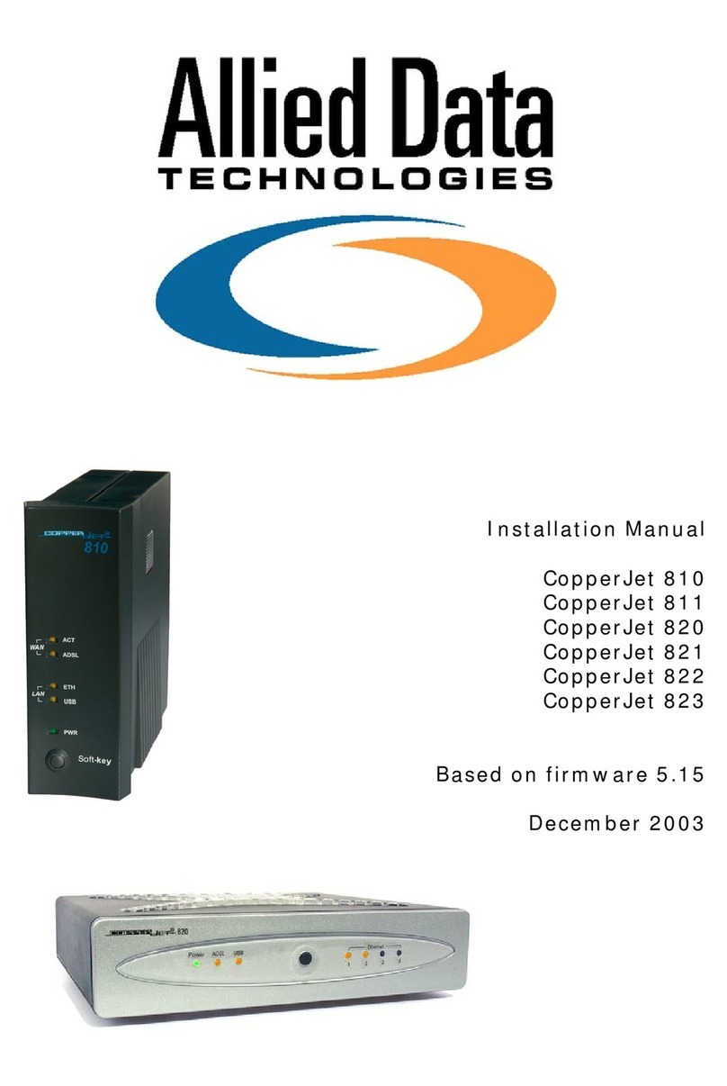
Allied Data Technologies CopperJet 816 User manual

Installation Manual
CopperJet 816
CopperJet 817
CopperJet 826
CopperJet 827
Based on firmware 5.15
November 2003

Document History
Date Version Status Description
10 Aug 2003 1.8 Release
27 Nov 2003 1.9 Release Firmware 5.15
15 Dec 2003 1.10 Release Updated

Product DISCLAIMER
This manual by ALLIED DATA TECHNOLOGIES B.V. (hereafter referred to as
ALLIED DATA TECHNOLOGIES) is a reflection of the current state of the products
described in it.
It has been our goal to provide a manual that is complete and clear to ensure
that our products are as easy to use. However, this manual may contain technical
inaccuracies and typing errors. As a result of rapid developments, we are also
obliged to reserve the right to implement technical modifications and
developments without prior notice. For this reason, ALLIED DATA TECHNOLOGIES
does not guarantee the contents of the manual and its permanent applicability.
Neither is ALLIED DATA TECHNOLOGIES liable for possible loss of information or
any improper use of information resulting from the consultation of this manual. In
particular, ALLIED DATA TECHNOLOGIES is not liable for any direct or indirect
damage (including loss of profits and comparable losses) resulting from the use
or improper use of this manual, even if ALLIED DATA TECHNOLOGIES or a
representative of ALLIED DATA TECHNOLOGIES has been informed that such
damage could arise. Of course, this does not detract us from our legal liability for
intentionally inflicted damage or damage on the basis of gross negligence.
In relation to the information mentioned in this manual, ALLIED DATA
TECHNOLOGIES does not guarantee that there are no industrial rights of
ownership (trademarks, patents, etc.). This also applies to commonly used brand
names, company names and product names, but these are subject to the relevant
trademark, patent and registered design laws.
The information is not to be copied, translated, reproduced or transferred or
stored on any electronic medium or other machine, neither wholly nor partly,
without prior permission in writing from ALLIED DATA TECHNOLOGIES.
The sale and use of software is subject to the ALLIED DATA TECHNOLOGIES
General Terms of Delivery and Payment as well as its License Terms.
Should any term regarding the disclaimer be or become void for legal reasons,
this will not affect the other terms.
Page 1

Contents
1Packaging contents ...............................................................................4
2LED Indicators and back panel ................................................................5
2.1 CopperJet 816/817 LED indicators....................................................5
2.2 CopperJet 816/817 back panel.........................................................5
2.3 CopperJet 826/827 LED indicators....................................................6
2.4 CopperJet 826/827 back panel.........................................................6
2.5 Softkey ........................................................................................7
3Connecting the CopperJet.......................................................................8
3.1 Connecting the CopperJet 816/817...................................................8
3.2 Connecting the CopperJet 826/827...................................................8
4Before you start....................................................................................9
4.1 IP Address Settings........................................................................9
4.2 Name Server Information ...............................................................9
4.3 ATM Settings.................................................................................9
4.4 PPP Settings .................................................................................9
5Configuring the CopperJet ....................................................................10
5.1 Accessing the build-in WebServer ..................................................10
5.1.1 Logging in to the WebServer ....................................................11
5.1.2 Changing the login settings......................................................11
5.2 Quickstart...................................................................................12
5.3 LAN Connections..........................................................................13
5.3.1 Create a new LAN connection ...................................................13
5.3.2 Delete a LAN connection..........................................................13
5.3.3 Edit a LAN connection..............................................................14
5.3.4 Configuring DHCP Server .........................................................15
5.3.4.1 Enabling DHCP Server..........................................................15
5.3.4.2 Disabling DHCP Server.........................................................18
5.3.5 Configuring DNS Relay ............................................................19
5.3.5.1 Enabling DNS Relay manually................................................19
5.3.5.2 Disabling DNS Relay manually...............................................20
5.3.5.3 Automatically discover DNS Relay addresses ...........................20
5.4 WAN Connections ........................................................................22
5.4.1 Configuring RFC1483 Bridged ...................................................23
5.4.1.1 Configuring DHCP on your networkcard ..................................24
5.4.2 Configuring RFC1483 Routed....................................................25
5.4.3 Configuring PPPoA routed.........................................................27
5.4.4 Configuring PPPoE routed.........................................................29
5.5 DSL Line.....................................................................................32
5.6 Security .....................................................................................33
5.6.1 Enabling Security....................................................................33
5.6.2 Configuring Security Interfaces.................................................34
5.6.3 Configuring Network Address Translation (NAT) ..........................35
5.6.3.1 Configuring NAT reserved mapping ........................................36
5.6.4 Enabling Firewall.....................................................................37
5.6.5 Enabling Intrusion Detection.....................................................38
5.6.6 Configuring Triggers................................................................38
5.6.6.1 Adding Triggers...................................................................38
5.6.6.2 Deleting Triggers.................................................................39
6Configuring Voice over DSL ..................................................................41
Page 2

6.1 Basic VoDSL Settings ...................................................................41
6.2 Advanced Voice over DSL Configuration..........................................42
6.2.1 ALAW/ULAW coding ................................................................43
6.2.2 Flash on hook timing...............................................................43
6.2.3 Initial ring timing for CLIP........................................................43
6.2.4 Ring cadence configuration support ...........................................44
6.2.5 Define Cadences.....................................................................44
6.2.6 Echo Cancellation....................................................................44
7Firmware and configuration management ...............................................46
7.1 Upgrading and downgrading firmware.............................................46
7.2 Uploading and retrieving configuration profile ..................................46
8CopperJet Revisions ............................................................................47
9Glossary ............................................................................................48
Page 3

Chapter 1: Packaging contents
1 Packaging contents
The packaging should contain the following parts:
All CopperJets
CopperJet 81x only
CopperJet 82x only
Caution!
To prevent overheating, make sure that the CopperJet has enough free space on
both sides and above to permit free airflow.
Page 4

Chapter 2: LED Indicators and back panel
Page 5
2 LED Indicators and back panel
Before you begin with the installation, please take a moment to become more
familiar with the LED indicators and back panel of the CopperJet.
2.1 CopperJet 816/817 LED indicators
Phone: The Phone led will blink when the connected POTS phone receives an
incoming call. During a analogue modem connection, blinking
indicates that echo cancellation is switched off.
The Phone led illuminates when the connected POTS phone is off-
hook.
USB: The USB led will illuminate when you connect the CopperJet to the
USB port on your PC, and the USB drivers are installed.
Eth: The Ethernet led will illuminate when you connect the CopperJet to
the Ethernetport on the PC or hub/switch.
ADSL: Blinking indicates that the DSL protocols starts handshaking.
Illuminates when the ADSL network is correctly configured and
connected.
Power: When the CopperJet is connected to a power source, the Power LED
will illuminate.
2.2 CopperJet 816/817 back panel
PWR USB
LINE ETH
1234
Phone
Back panel
PWR: Only the power adapter that comes with the package can be
connected to the power jack.
PHONE: To connect your POTS Telephone to the CopperJet.
LINE: To connect the CopperJet to the ADSL line of your provider.

Chapter 2: LED Indicators and back panel
Page 6
USB: To connect the CopperJet to the USB port of the PC. Note: not
available on all units.
ETH: To connect the CopperJet to the Ethernet port of the PC, hub or
switch.
2.3 CopperJet 826/827 LED indicators
Power: When the CopperJet is connected to a power source, the Power LED
will illuminate.
Phone: The Phone led will blink when the connected POTS phone receives an
incoming call. During a analogue modem connection, blinking
indicates that echo cancellation is switched off.
The Phone led illuminates when the connected POTS phone is off-
hook.
ADSL: Blinking indicates that the DSL protocols starts handshaking.
Illuminates when the ADSL network is correctly configured and
connected.
USB: The USB led will illuminate when you connect the CopperJet to the
USB port on your PC, and the USB drivers are installed. Note: not
available on all units.
Ethernet: The Ethernet led will illuminate when you connect the CopperJet to
the Ethernetport on the PC or hub/switch.
2.4 CopperJet 826/827 back panel
PWR USB
LINE
1234
Phone
Back panel
Ethernet
1234
PWR: Only the power adapter that comes with the package can be
connected to the power jack.
PHONE: To connect your POTS Telephone to the CopperJet.
LINE: To connect the CopperJet to the ADSL line of your provider.

Chapter 2: LED Indicators and back panel
Page 7
USB: To connect the CopperJet to the USB port of the PC. Note: not
available on all units.
Ethernet: To connect the CopperJet to the Ethernet port of the PC, hub or
switch.
2.5 Softkey
The purpose of the Softkey is to return the CopperJet to its factory default
settings. When pressing and holding the button, the lights will start to blink
indicating that the default configuration is about to be restored. When keeping
the button pressed, the lights will stop blinking and stay on indicating that the
default configuration is restored. The softkey can be released and the CopperJet
will restart automatically with the default configuration.
Important: Never disconnect the power from the modem while the
softkey is pressed.

Chapter 3: Connecting the CopperJet
Page 8
3 Connecting the CopperJet
To connect the CopperJet to the computer, you must have installed an Ethernet
10Base-T card in your computer. You need to have a static IP address on your
network card that is in the same subnet as the web interface IP address of the
CopperJet. The default web interface IP address for Ethernet is 172.19.3.1. For
USB, the default IP address is 172.20.3.1. When using the default IP addresses,
your network card can have the following IP address 172.19.3.2 with subnetmask
255.255.0.0
3.1 Connecting the CopperJet 816/817
3.2 Connecting the CopperJet 826/827

Chapter 4: Before you start
Page 9
4 Before you start
The following information may be required for configuring the CopperJet. If you
do not know if all the information is needed, please contact your DSL service
provider before proceeding with the configuration.
4.1 IP Address Settings
The CopperJet allows the ISP to dynamically assign IP Address settings. If your
ISP requires static setting of specific IP address information, you need to receive
the following information:
• IP Address
• Subnet Mask
• Default Gateway
4.2 Name Server Information
The CopperJet allows the ISP to dynamically assign Name Server Address
settings. If your ISP requires static setting of specific DNS address information,
you need to receive the following information:
• Primary DNS Address
• Secondary DNS Address
4.3 ATM Settings
The following ATM settings should be available during configuration
• ATM Virtual Path ID (VPI); Required if not using default value
• ATM Virtual Circuit ID (VCI); Required if not using default value
• Encapsulation type; Required if not using default value
• Modulation type; Required if not using default value
4.4 PPP Settings
The following PPP settings should be available during configuration of a PPP
connection.
• Username (for PPP applications only)
• Password (for PPP applications only).

Chapter 5: Configuring the CopperJet
Page 10
5 Configuring the CopperJet
Configuration of the CopperJet ADSL router can be done through the build-in
HTTP WebServer. Users can access this WebServer using a standard browser like
Netscape Navigator or Microsoft Internet Explorer.
5.1 Accessing the build-in WebServer
To access the build-in WebServer, you need to launch a HTTP Web browser. Enter
the IP address of the CopperJet in the address bar.
The default Ethernet IP address of the CopperJet is: 172.19.3.1
The default USB IP address of the CopperJet is: 172.20.3.1
The address for accessing the CopperJet’s WebServer through an Ethernet
connection would be HTTP://172.19.3.1/
The first time that the WebServer is launched during a session, the Welcome!
message is displayed at the top of the Status homepage. This message is
replaced by the Status heading once the page is automatically or manually
refreshed.

Chapter 5: Configuring the CopperJet
Page 11
5.1.1 Logging in to the WebServer
The first time that you click on an entry from the left-hand menu to display a
page, a login box is displayed. You must enter your username and password to
access the pages. The default network login is:
Username: admin
Password: admin
Click on OK. You can now configure your CopperJet using the WebServer.
5.1.2 Changing the login settings
To change the default username and/or password, go to the Configuration menu
and click on Authentication. The Authentication page is displayed.
This page displays the users that are currently defined. To change the username
and/or password click on the Edit user…hyperlink of the user you want to edit.
The Details for user page is displayed.
On this page you can change the password or access rights of the specific user.
When the changes have been made, click on Apply. To delete the specific user,
click on Delete this user.
When finished configuring the users, go to the Configuration menu and click on
Save config to save the new settings into the CopperJet.

Chapter 5: Configuring the CopperJet
Page 12
5.2 Quickstart
With the Quickstart option you can configure your CopperJet in only a few steps.
The number of steps is depending on the specific ISP network.
To use the Quickstart, click on Quickstart (on the left hand side).
The Quickstart page is displayed.
Select your ISP network from the dropdown-list and click on OK. Some settings
may already been pre-configured. This is shown at the top op the page Pre-
defined Settings.
Depending on the ISP selected, you may have to enter more information like fill
in Username and Password.
If you have finished entering all the information, click on OK and the Store
Configuration & Restart Device page is displayed.
Click on Store.
The configuration will now be saved into the unit and the unit will reboot.
After reboot the CopperJet is correctly configured for your ISP network.
Note: Depending on the pre-defined settings, your network card settings may not
be correct anymore. Make sure that your network card is correctly configured.

Chapter 5: Configuring the CopperJet
Page 13
5.3 LAN Connections
LAN Connections allows you to add, configure and remove the Ethernet and/or
USB connections. It is also used to assign IP addresses to these connections. The
Ethernet connection CANNOT be removed only edited.
Go to the Configuration menu and click on LAN connections. The LAN Connections
page is displayed.
This page displays a table that lists all existing LAN connections. This table
contains the following information:
Service Name: Name of the LAN port
IP/Bridge Interface: Internal name of the LAN port.
Description: Description of the connection.
Creator: Which management entity the service was created in;
CLI, Firmware, WebAdmin or Factory Defaults.
5.3.1 Create a new LAN connection
To create a LAN connection, click on the Create a new service command. A page
containing the service options that are available to you will be displayed. Select
the service that you want to create. Click on the Configure button to display the
service configuration page. You need to enter information, specific to the service
that you are creating.
Click on Apply. The LAN connections page is displayed. The table now contains
details of the service that you have just created.
5.3.2 Delete a LAN connection
To delete a configured LAN connection, click on the Delete… hyperlink of the LAN
connection. Check the details of the LAN connection that you want to delete, then
click on Delete this connection.

Chapter 5: Configuring the CopperJet
Page 14
5.3.3 Edit a LAN connection
To update or edit your LAN IP address, click on the Edit hyperlink of the LAN
connection you want to update or edit. The Default LAN Port page is displayed.
This page contains the Default LAN Port table that allows you to:
Use DHCP: The CopperJet receives its LAN IP address from an
external DHCP server connected to this LAN interface.
IP Address: Configure the Primary (default) IP address and
subnet mask for the IP interface.
Secondary IP Address: Create or configure a Secondary IP address and
Subnet mask for the interface. A Secondary IP
address is usually used if you have defined two
subnets on a LAN and wishes to route them through
the same IP interface.
Once you have configured your IP addresses, click on the OK button. A message
is displayed confirming that your address information is being updated. You may
need to enter the new IP address in your web browser address box.
When finished configuring, go to the Configuration menu and click on Save config
to save the new settings into the CopperJet.
Note: Make sure, after you have changed the LAN IP addresses, that your
network card is in the same subnet as your new CopperJet LAN IP address.
Note: The USB connection (ethernet-1) does not have a Secondary IP address.

Chapter 5: Configuring the CopperJet
Page 15
5.3.4 Configuring DHCP Server
DHCP allows you to dynamically assign IP address to the computers connected to
the Ethernet or USB interface of the CopperJet. The CopperJet allows multiple
DHCP Servers for multiple IP subnets. Usually, you would only require 1 DHCP
Server.
This option allows you to enable, disable and configure the DHCP server on your
CopperJet. By default, the DHCP Server is disabled.
5.3.4.1 Enabling DHCP Server
To enable the DHCP Server, go to the Configuration menu and select DHCP
server.
The DHCP Server page is displayed.

Chapter 5: Configuring the CopperJet
Page 16
Select DHCP Server en click on Configure. The DHCP Subnet page is displayed.
This page allows you to:
• Set the subnet for the DHCP Server manually OR use the same subnet
used on the IP interface by selecting Use Subnet of IP interface.
• Set the DHCP address range manually OR use a default range of 253
addresses by selecting Use Default Range.
• Set the default and maximum lease times for this DHCP Server.
• Set your CopperJet to give out its own IP address as the DNS Server
address OR manually set the primary and secondary DNS Server
addresses. When Use Router as DNS Server is selected, DNS Relay will be
enabled.
• Set your CopperJet to give out its own IP address as the default Gateway
address. In most situations this is enabled.
Once you have entered new configuration details for your DHCP server, click on
OK.
On the next screen, at the bottom, click on the Configure the DHCP server button
to activate the DHCP server.

Chapter 5: Configuring the CopperJet
Page 17
If you want to carry out further configuration of your DHCP Server, click on the
Advanced Options page at the bottom of the DHCP configuration page. The Edit
DHCP Server page is displayed.
This page allows you to edit the options that appear on the DHCP Server page.
Default lease time: If the client that requests the lease, does not ask for
a specific expiry time (43200) the default time (in
seconds) will be assigned to a lease.
Allow Bootp: True: DHCP server responds to BOOTP queries.
False: DHCP server does not respond to BOOTP
queries.
Max lease time: The maximum time (in seconds) that a subnet
assigns to a lease if the client requesting the lease
does not ask for a specific expiry time (86400).
Allow Unknown Clients: True:Allows IP addresses to be dynamically assigned
to unknown clients.
False: Does not allow IP addresses to be dynamically
assigned to unknown clients.
Enabled: True: DHCP server is enabled.
False: DHCP server is disabled.
After changing the settings, click on the Change button to activate the new
settings. Go to the Configuration menu and click on Save config to save the new
settings into the CopperJet.

Chapter 5: Configuring the CopperJet
Page 18
5.3.4.2 Disabling DHCP Server
To disable the DHCP Server, go to the Configuration menu and select DHCP
server.
The DHCP Server page is displayed.
Select Disabled and click on Configure to disable the DHCP Server. The DHCP:
disable server and relay agent page is displayed. At the bottom of the page, click
on Apply. The DHCP Server page is displayed to ensure that the DHCP Server is
disabled.
Go to the Configuration menu and click on Save config to save the new settings
into the CopperJet.
This manual suits for next models
7
Table of contents
Other Allied Data Technologies Network Router manuals
Popular Network Router manuals by other brands
Paradyne
Paradyne Hotwire 6371 installation instructions
D-Link
D-Link Express Ethernetwork DI-704P Quick installation guide
SonicWALL
SonicWALL SonicWave 641 reference guide
TP-Link
TP-Link Aginet MX515v Quick installation guide
D-Link
D-Link DIR-518L Quick installation guide
Maestro
Maestro E205XT02 quick start guide
